Table of Contents
Advertisement
Quick Links
FUEL LEVEL SENSOR LLS 20160
Installation manual
LLS 20160-1000
LLS 20160-1500
A-A. Tiimanni 1, 21004 Narva, Estonia.
Tel.: +372 3569590, Fax: +372 3566292 , e-mail: info@omnicomm-online.com
www.omnicomm-online.com
All rights reserved. ©2016 OMNICOMM
LLS 20160 – 700
v1.16
Model:
LLS 20160-2000
LLS 20160-2500
LLS 20160-3000
Advertisement
Table of Contents

Related Manuals for Omnicomm LLS 20160


Summary of Contents for Omnicomm LLS 20160
- Page 1 FUEL LEVEL SENSOR LLS 20160 Installation manual Model: LLS 20160 – 700 LLS 20160-1000 LLS 20160-1500 LLS 20160-2000 LLS 20160-2500 LLS 20160-3000 A-A. Tiimanni 1, 21004 Narva, Estonia. Tel.: +372 3569590, Fax: +372 3566292 , e-mail: info@omnicomm-online.com www.omnicomm-online.com All rights reserved. ©2016 OMNICOMM...
-
Page 2: Table Of Contents
) ........................14 TEP UEL SENSOR CALIBRATION MPTY ..............................21 TEP UEL TANK CALIBRATION ................................ 23 TEP ALIBRATION TABLE 20160 ........................24 TEP EALING OF THE INSTALLED MODEL BRIEF DESCRIPTION OF LLS MONITOR SOFTWARE .................... 26 : ................................... 26 UBWINDOWS : ....................................26 UTTONS ................................... 26 UNCTION KEYS REVISION HISTORY ............................27 APPENDIX A ..............................28 APPENDIX B ..............................30 APPENDIX C ..............................31 All rights reserved. ©2016 OMNICOMM... -
Page 3: Introduction
Introduction. LLS Model 20160 (hereafter LLS) liquid level sensors are solid-state devices with no moving parts. The sensors utilize the capacitive technology to produce accurate liquid level detections of standard factory grade DIESEL OIL and PETROLIUM. Warning! The LLS liquid level sensors are strictly prohibited to use in any liquids which are not the factory grade carbon fuels or contain: BIOFUEL, METHANOL, ETHANOL, UREA and similar aggressive components in pure form or as additives for factory grade carbon fuels for use in INTERNAL COMBUSTION ENGINES. The wrong polarity (-) or (+) connection of power supply can damage or destroy the device. Prohibited for test or use in water and any other liquids, which are not factory grade of carbon fuels. For evaluation purposes, it is acceptable to use the sensor in any kind of mineral or lube oil. Fit the plastic insulation cap on the end of the central rod after installation accordingly with installation guide. To be installed, calibrated, tested only by qualified authorized person (installer, technician, mechatronic). Positive (+) of board power supply should be connected through enclosed fuse in the point of connection. VERY IMPORTANT. Before any “wet” testing of LLS 20160 (even if you don’t cut its tube), it’s necessary to take off transportation rubber sealing ring and install Insulating cap (enclosed). See four photos below. Transportation rubber Transportation rubber End of the tube and End of the tube and sealing ring at the end sealing ring, pulled central rod, without central rod, with of LLS 20160 tube and out of the tube transportation rubber installed Insulating cap central rod sealing ring Detailed instruction how to cut LLS tube and install insulating cap will be described at page 7 of this manual. All rights reserved. ©2016 OMNICOMM... -
Page 4: Technical Specifications
Output interface: Physical level RS-232 and EIA(RS)-485 Speed of data transmission, bps 1200, 2400, 4800, 7200, 9600, 14400, 19200, 38400, 57600, 115200 Mode of operation continuous Discrimination (resolution), points 1…4095 Offset of the digital scale, points 0…1023 Ratio error of the level detection: Rate of ambient temperature change – 60 °С … + 60 °С, % max ±0,8 Rate of ambient temperature change – 60 °С … + 80°С, % max ±1,0 Operation temperature, C –40,0 … +80,0 Temperature range (critical points), C –60,0 … +85,0 Dust and water protection IP57 Time interval of data output in “automatic” mode, seconds 1…255 Hardware configuration Operation principle: capacitive. Output: RS-232 and EIA-485 interfaces. Standard probe lengths: 700, 1000, 1500, 2000, 2500, 3000 mm. LLS contributes two (RS-232 and EIA-485) data output interfaces, selectable. These sensors have galvanic insulation between power supply circuits, interface’s lines and measuring part, including ground circuits and central rod. All rights reserved. ©2016 OMNICOMM... -
Page 5: Hardware Installation
HARDWARE INSTALLATION Step 1. Mount Hole Location The right mounting location for LLS on the tank is the mechanical centre of the tank's upper part (Figure 1a). Figure 1a. Mounting location for LLS. Figure 1b. Mounting holes locations and diameters. The wrong locations for LLS are the edges of the tank's or reservoir's upper part. Wrong LLS location might result in spurious draining and fuelling (Fig. 1a). In some cases of vehicle's configuration it’s impossible to get to the mechanical center of the tank's (or reservoir's) upper part. In this case the tank should be dismounted off the vehicle for the correct (and easy) LLS installation. Step 2. Drilling holes at the Fuel Tank Figure 2a. Hole Saw for main hole, 35 mm Figure 2b. Hole Saw 35 mm diameter, view from the tip of drill bit. diameter, general view. All rights reserved. ©2016 OMNICOMM... -
Page 6: Step 3. Fuel Tank Depth Measuring And Lls Tube Marking
Figure 2c. Drilling the main hole at the fuel tank (the hole saw Figure 2d. The main hole is done. here is similar with Figures 2a, 2b hole saw, but not the same). The main hole is drilled with Hole Saw 35 mm diameter, using electric drill. The sensor’s tube should be cut accordingly with the adjusted depth of fuel tank (exact depth of the fuel tank, minus 8 – 10 mm). Four small holes for LLS fixing screws are drilled with 4.0 mm diameter drill bit, accordingly with Figure 1b. Rubber gasket (it is seen at Figures 2c and 2d, big photo of Rubber gasket is at Figure 9d) can be used as prototype for creating exact drilling pattern. Otherwise for marking of the holes can be used fixing plate of LLS head. Step 3. Fuel Tank depth measuring and LLS tube marking. Figure 3a. Measuring of the Fuel Tank’s depth Figure 3b. Marking the cutting line of LLS tube (from the bottom to the top of the Tank’s top plate). (Measurement Fig. 3a, minus 8-10 mm). All rights reserved. ©2016 OMNICOMM... -
Page 7: Step 4. Lls Tube Cutting
Step 4. LLS tube cutting LLS tube was can be cut by any suitable tool. Below are photos of LLS tube cutting with pipe cutter (Figure 4a) and hand Central rode and tube MUST be the same length. saw (Figure 4b). Figure 4a. Cutting LLS tube with pipe cutter Figure 4b. Cutting LLS tube with hand saw. (central rod should be cut with another tool, for example, with hand saw, Figure 4b). Minimum length of the sensor’s tube and rod cannot be less than 150 mm. ¼ After the sensor tube was cut for proper length, the insulation cap should be filled with sealant (silicon compound) for DO NOT PUT ANY SEALANT IN TUBE. volume and fit on core rod (see the next step). Step 5. LLS tube insulation cap fitting. Figure 5a. Cut LLS tube, close view. Figure 5d. Inserting sealant in the hole of Figure 5c. Inserting sealant in the hole of the cap - beginning. the cap - continuation. Figure 5d. Insulating cap view after Figure 5e. Insulating cap is almost in Figure 5f. Insulating cap in position. applying silicone. position. All rights reserved. ©2016 OMNICOMM... -
Page 8: Step 6. Installation (Fitting) Procedure
After fitting the cap you need to wait 10-15 minutes for "surface skin" of silicone. Step 6. Installation (fitting) procedure. Sensor intends to be fitted on the fuel tanks of the motor vehicle, heavy equipment, or storage, transport tanks. Need to define the place of fitting and way of fastening before installation according to the design of the fuel tank. Some small amount of silicone must be applied to the both sides of rubber gasket before final fitting (figure 6): Figure 6. Rubber gasket with applied silicone sealant. After applying and before final fitting, you also need to wait 10-15 minutes for "surface skin" of silicone. There are 3 options of fastening: Option 1: Metal made tank or plastic tank, the wall thickness up to 3,0 mm The 5 holes should be drilled (one central for the probe insertion and 4 satellite holes for fastening).The rivets with screw are fitted in the fastening holes (4 pieces).Then sensor is fitted on the tank and fasten with screws Option 2: Metal made tank, the wall thickness more than to 3,0 mm The 5 holes should be drilled (one central for the probe insertion and 4 satellite holes for fastening). The thread size M5 (metric) should be made in the fastening holes (4 pieces).Then sensor is fitted on the tank and fastens with M5 screws Figure 6a. Four marks for 7mm holes are Figure 6b. 7 mm diameter holes are Figure 6c. 7 mm diameter (for M5 round done. done. nuts) round nuts are in position, ready to be fixed. All rights reserved. ©2016 OMNICOMM... - Page 9 Figure 6d. Nut Riveter is ready to work, Figure 6e. Nut Riveter is ready to work, Figure 6f. Round nut is inserted in 7mm general view close view (round M5 nut is in position diameter hole, ready to be riveted. already). Figure 6g. Four nuts are in positions, (ready to be tighten), rubber gasket is in position as well. Close view of one bolt, washers and rubber gasket. Option 3: Plastic made tank, wall thickness more than to 3,0 mm The 5 holes should be drilled (one central for the probe insertion and 4 satellite holes for fastening). Special drilling adapter (crown drill bit 35 mm.) is used to make a central hole in all cases. All rights reserved. ©2016 OMNICOMM...
-
Page 10: Software Installation
SOFTWARE INSTALLATION Step 7. UNU device installation procedure: Our UNU device has internal USB-Serial port bridge, operated by FTDI FT232R electronic chip. In order to use UNU device, it is necessary to install hardware drivers for the operation system. For Windows XP/Vista execute the driver installation file from enclosed Omnicomm CD or download latest version of the driver from FTDI company web site: http://www.ftdichip.com/Drivers/VCP.htm. Driver for Windows 7 should be installed automatically. For other operation systems, use the indicated link to find necessary driver Step 8. OMNICOMM LLS Monitor package installation procedure: Before installation of OMNICOMM LLS Monitor you need to download this software from Omnicomm website or from Omnicomm CD. Click icon to start installation procedure. See screenshot below. Click “I Agree” to continue. See Screenshot below. All rights reserved. ©2016 OMNICOMM... - Page 11 Click “Install” to continue. See screenshot below. It will be replaced by next window, see screenshot below. All rights reserved. ©2016 OMNICOMM...
-
Page 12: Step 9. Preparing Unu For Working With Lls
Click “Close” to finish installation. This window will disappear; OMNICOMM LLS Monitor software packet is successfully installed. You can create shortcut and place it on the Desktop Step 9. Preparing UNU for working with LLS: Connect Adapter UNU to LLS and PC accordingly with Figures 8a – 8i. Figure 8a. Adapter UNU with connected AC/DC adapter, USB Figure 8b. Adapter UNU cable and RS-232 (blue cable) of LLS connection cable, general with connected cables, close view. view. All rights reserved. ©2016 OMNICOMM... - Page 13 Figure 8c. Adapter UNU, view from RJ-45 socket, blue (RS-232) Figure 8d. Adapter UNU, view from RJ-45 socket, Red (EIA- cable is connected, Red LED(s) are lighting continuously, and 485) cable is connected, Red LED(s) are lighting continuously, Green LED is lighting periodically, once per second. and Green LED is lighting periodically, once per second. Figure 8e. Adapter UNU, USB plug Figure 8f. 6-contacts Male plug of LLS. Figure 8g. 6-contacts Female socket of connected with USB socket of Notebook UNU cable, connecting LLS with UNU. PC. Figure 8h. Connecting of LLS and Sensor, Figure 8i. Connecting of LLS and Sensor, 6-contacts socket and plug are connected. 6-contacts socket and plug are ready to be connected All rights reserved. ©2016 OMNICOMM...
-
Page 14: Step 10. Diy Plastic Fuel Pipe (Tank) For "Empty - Full" Calibration
Step 10. DIY plastic fuel pipe (tank) for “Empty – Full” calibration It’s reasonable to create small and easy to use “calibration tank” for “Empty – Full” calibration. Simple decision could be drain plastic pipe suitable length. One meter length tube will suit for standard 75 cm LLS tube. Suitable inside diameter of the pipe is 40 – 50 mm. It should be corked up with cork from the bottom and have open top. Figure 9b. The top of the pipe. Figure 9c. Cork for this pipe. Figure 9a. Drain plastic pipe about 1 meter Figure 9d. Cork is half in position. Figure 9e. Cork is in position. It is top length. for a moment, but it will be the bottom in our calibration fuel pipe (tank). Step 11. Fuel sensor calibration (Empty – Full) Attention!!! (IMPORTANT!!!) Sensor adjustment should be provided for the fuel; vehicle or machine is really working with, no any other fuel! Fuel must be clean (no any visible particles or additives), fresh, drained from fuel tank, or, in case of taken from storage, must be shaken well before calibration procedure. The LLS sensor scale should be adjusted after tube cutting. “LLS Monitor” software provides it. Click shortcut of “LLS Monitor” and OMNICOMM LLS Monitor window will appear, see screenshot below All rights reserved. ©2016 OMNICOMM... - Page 15 Figure 10a. LLS Monitor window Then press “Service” button and chose the COM-port, connected to UNU Figure 10b. “Settings” window. Change COM-ports, if necessary, until you get connection with LLS In case you have trouble with comport, or just want to change it for another number, you can change comport number, as described below. Start → Control Panel → System → System properties → Hardware → Device Manager. All rights reserved. ©2016 OMNICOMM...
- Page 16 Figure 10c. Changing Com-port “Device Manager” window In this window you select existing Com-port and click it with right button of the mice, in popped-up window select “properties” You will see next window: Figure 10d. Changing Com-port “USB serial port” window Press “Port Settings” and in new window press “Advanced” All rights reserved. ©2016 OMNICOMM...
- Page 17 Figure 10e. Changing Com-port “Advanced Settings” window Now you can change comport in “Com Port Number” window, press OK for to finish. Figure 10f. LLS Monitor window with correctly selected Com-port All rights reserved. ©2016 OMNICOMM...
- Page 18 Submerge sensor tube completely into the fuel and pull it out. Do it slowly (especially submerging), for avoiding spillage of the fuel. Figure 10h. LLS Monitor window in Adjustment of LLS mode, ready for “Empty” setting Figure 10g. LLS sensor “Empty” Figure 10i. LLS Monitor window in Adjustment of LLS mode. Empty calibration position (out of fuel, value is set. after 2 minutes waiting) . You can see the drain plastic pipe, filled with a fuel, to the right of the LLS, Wait again for 2-3 minutes, for LLS tube became free of fuel (no any drops of fuel must come down at that moment), except some “film” of the fuel, covering LLS tube and rode. This is necessary for proper “Empty” calibration. Press “Empty” button in “CALIBRATION” window to save empty tank sensor value. If sensor configuration was done correctly, the “Set” mark will appear opposite the “Empty” button (Figure 10i). There will appear value for CNT1, in our case CNT1 = 60490 (see Figure 10i). If the procedure was wrong, the “CNT1=167772…” mark appears (Figure 10k), and procedure has to be done again. All rights reserved. ©2016 OMNICOMM...
- Page 19 Figure 10j. LLS sensor “Full” calibration position, (LLS tube is completely Figure 10L. LLS Monitor window in Adjustment submerged into the drain plastic pipe with fuel), after 2 minutes waiting. of LLS mode, ready for “Full” setting. Next step submerge LLS tube completely into the fuel (slowly and carefully). Wait for 2-3 minutes to permit air bubbles to leave the LLS tube, and fuel to occupy completely inside LLS tube space. This is necessary for proper “Full” calibration. Figure 10m. LLS Monitor window in Adjustment of LLS mode, “Full” is set. Press “Full” button in “CALIBRATION” window to save full tank sensor value. If the sensor configuration was made correctly, the “Set” mark will appear opposite the “Full” button. There will appear value for CNT2, in our case CNT2 = 903882 (see Figure 10m). If the procedure was wrongly provided, the “CNT2=167772…” mark appears, and procedure have to be done again. See screenshot below: For to complete calibration, press “Finish” button. You will see window Figure 10n. All rights reserved. ©2016 OMNICOMM...
- Page 20 Figure 10n. LLS Monitor window after “Finish” button is pressed ( the calibration is completed). “Empty – Full” calibration is successfully performed! All rights reserved. ©2016 OMNICOMM...
-
Page 21: Step 12. Fuel Tank Calibration
Step 12. Fuel tank calibration Figure 11a. Refueling station with fuel tank, fuel pumps, fuel Figure 11b. Vehicle’s fuel tank ready for calibration. meter, fuel hoses, control switches, etc. LLS sensor should be permanently installed at the fuel tank before starting calibration process. The best location is in the middle of the fuel tank, or as close to the middle, as possible (sees Figure 11c). The tip of insulating cap should be 8 – 10 mm higher of tank’s bottom. In this case we avoid direct electrical contact with the bottom (insulating cap could be mechanically damaged because of vibration, if the tip of cap will touch tank’s bottom) and direct contact with Don’t forget to put square rubber gasket on water/debris, usually presenting close to the tank’s bottom (see Figure 11d). the top of the fuel tank before mounting of LLS! See Figures 11e and 11f. Figure 11c. Correct and wrong LLS location in the fuel tank. All rights reserved. ©2016 OMNICOMM... - Page 22 Make the calibration of fuel tank using RS-232 interface. Table 2 is example of calibration table for RS-232 and EIA-485 interfaces. Calibration is done through filling the fuel tank with the same quantity (volume) lots (steps) of the fuel, from empty to full. For obtaining correct results necessary to drain the fuel tank, as much, as possible. Filling the tank should be done with a measuring tank or step by step under the control of a discharge gauge's indications. The tanking step is defined by the installer depending on the tank. The lower the step, the more precise the calibration is. Recommended tanking steps (Table 1): Table 1. Volume of the tank, liters Tanking step, liters 0-100 101-500 501-1000 more than 1000 as affordable Remember, that the more precise (more number of steps, but smaller one step capacity) the tanking is done, the higher is accuracy of further gauging. It is advisable to do not less than 20 tanking steps. All rights reserved. ©2016 OMNICOMM...
-
Page 23: Step 13. Calibration Table
IMPORTANT! During calibration process wait for green signal (Level Stabilization Completed, like on the screen) after each tanking step, and then write down the value of N. It’s necessary for obtaining stable, correct values of N for each step. !!!Attention: repeating values of the N are not written in the table. The N column must always begin with 0 and end with 1023. For calibration (calibration) the fuel tank, we use bottom part of LLS Monitor). See screenshot below. Step 13. Calibration table. Figure 11e. LLS Monitor window, calibration procedure, 120 liters in the fuel tank All rights reserved. ©2016 OMNICOMM... -
Page 24: Step 14. Sealing Of The Installed Lls Model 20160
N = 0 for the first line, no exceptions!!! Second – one before last lines Each of N values could be written after portion (step) of the fuel is added into fuel tank and 30 seconds passed (for to obtain stable, correct N value). One before last line or last line. One before Last line or Last line (for full tank) . Liters are inserted accordingly with real fueling. N value is written from LLS monitor window as it is, even if it is not equal to 1023 (by any reason, none standard shape of tank, none horizontal location of vehicle, etc.). In this case it is not the last line, but line before last. This is the last line, in case you really see 1023 value for N. Last step can be smaller, than usual step, because of completely full tank (otherwise you can make spillage of the fuel). In our sample table (Table 2) it could be 176 or 178 liters, for example. The very last line For the very last line you have to add 1 liter to former line Liters value and write 1023 for N. (In case you did not get 1023 as N value in the last step). N = 1023 for the very last line, no exceptions!!! The last comment. From the very first to very last line liters value increases in fixed steps, except the very last line. For the very last line it is former liters value + 1 liter. N value for each next line has to be greater than N value in former line(s). If you have situation when in any further line value of N is decreasing, something is wrong and it’s necessary to check electric connection, repeat “empty-full” LLS calibration, and repeat calibration procedure again. Step 14. Sealing of the installed LLS model 20160 Installation of a protective seal on the product Important! Installation of the seal is intended only for the products fixed with the help of bolts. 1) Overlap the holes of the inner ratchet with external holes of the seal. 2) Pass the sealing wire through the holes in two bolts, wrap the wire around the metal hose as it is shown in the figure (Figure 12a) and pass the ends of the wire through the holes of the seal. 3) Spin the wire by rotating the handle of the ratchet clockwise to achieve complete tension. 4) Break off the ratchet handle. All rights reserved. ©2016 OMNICOMM... - Page 25 Figure 12a Installation of protective seals on the connectors For fuel level sensor LLS 20230 - install a protective seal on the connector (Figure 36). For fuel level sensor LLS 20230 - install protective seals on both connectors of BIS 20240 similarly to protective seal installation for fuel level sensor LLS 20230. Figure 12b 1) Pass the sealing wire through the holes of the product connectors and the female connector so that the wire runs from different ends of the connectors (Figure 12b). 2) Pass the ends of the wire through the holes of the seal. 3) Spin the wire to achieve complete tension and break off the handle of the ratchet. All rights reserved. ©2016 OMNICOMM...
-
Page 26: Brief Description Of Lls Monitor Software
"No" no filtration. Used when filtering is performed by external device. "Minimum" filtration is used in cases of sensor installation in stationary fuel storage tanks or inactive objects (diesel generators, construction equipment). "Medium" filtration is used in cases of using vehicle under normal driving conditions (trip transportation, cargo and etc.). "Maximum" filtering is used in cases of vehicle in heavy traffic conditions (construction machines, vehicle, working in off-road conditions, agricultural machinery). • Hard Environment Mode –mode, including additional filtration releases of measured values, takes into account difficult working conditions of sensor (beats while driving on the bumps, large fluctuations of fuel, the presence of waves in the tank, etc.) "On" - performed additional filtration sensor readings. "Off" - additional filtration is not performed. " Buttons: • Get Parameters – new request of data, useful (for example) when another LLS is connected • Set Parameters – provides possibility to change parameters and save them accordingly. • Update firmware – provides possibility to download new version of firmware. • LLS Adjustment – button to start Empty – Full calibration. • About – info about program. Function keys • F1 – to see the calibration chart; • F2 – to save the calibration table into the text file; • F4 – to switch on synchronization with the LLS 20160 readings (i.e. the current reading will be recorded as a value in the table); • F5 – to switch off the synchronization of the LLS 20160 (in this mode, you may complete the table manually, ignoring the sensor readings). All rights reserved. ©2016 OMNICOMM... -
Page 27: Revision History
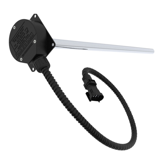
REVISION HISTORY Date Version Description 11.09.13 1.13 Initial release 14.09.15 1.15 Changed company name 11.02.16 1.16 Minor update of procedures All rights reserved. ©2016 OMNICOMM... - Page 28 Appendix A Main view, pinout and wire colors Picture 1. LLS 20160 model view and pigtail with 6-pin male part of the coupling connector. Pigtail’s length is 0.7m. (only for reference, appearance is subject to change without notice) Picture 2. LLS connector terminals location view 7 meters extender cable is supplied in set with LLS sensor. It is a pigtail, protected by plastic corrugated tube with 6-pin female part of the coupling connector on one side and 6 loose wires on the other side (see picture below).
- Page 29 LLS model 20160 Wiring and pinout table Output number Wire color on extender 7 m. cable Output description Brown Power source «+» White Ground «-» Pink RS-232 “Tx” Grey RS-232 “Rx” Orange-White EIA-485 “Line A” Blue-White EIA-485 “Line B” All rights reserved. ©2016 OMNICOMM...
- Page 30 Appendix B LLS model 20160 dimensions * *All dimensions in millimeters (mm) All rights reserved. ©2016 OMNICOMM...
- Page 31 Appendix C Basic requirements for the quality of proper sealant are described below: Sealant must be gasoline, diesel, and oil resistant; Water absorption of the sealant should be slight; Sealant should not contain small metallic inclusions (for example copper particles); Sealant should be completely non-conducting, and it should not contain graphite; Working temperature range should not be shorter than LLS’s range. All rights reserved. ©2016 OMNICOMM...
Need help?
Do you have a question about the LLS 20160 and is the answer not in the manual?
Questions and answers