
Related Manuals for Omnicomm LLS-Ex 5


Summary of Contents for Omnicomm LLS-Ex 5
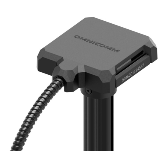
- Page 1 Omnicomm LLS-Ex 5 Fuel Level Sensor and BIS-MX Intrinsic Safety Unit User Manual 06.07.2020...
-
Page 2: Table Of Contents
Special conditions for safe operation of Omnicomm LLS-Ex 5 Preparation Fuel Tank Preparation Sensor Preparation Setting “Empty/Full” Calibration Omnicomm LLS-Ex 5 Sensor Settings Installation and Connection Connecting the Omnicomm LLS-Ex 5 fuel level sensor to an external device using BIS- Calibration Sealing... - Page 3 Recommendations for the assembly of the fuel sensors from 3 to 6 meters in length Fuel level sensor installation recommendations for cylindrical fuel tanks Appendix. List of equipment for Omnicomm LLS-Ex 5 fuel level sensors and BIS-MX Intrinsic Safety Unit installation Omnicomm LLS-Ex 5 sensor...
-
Page 4: General Information
Fuel level sensors also measure the temperature. RS-485 or RS-232 interfaces are used to exchange information with the device. The Omnicomm LLS-Ex 5 fuel level sensor is installed on special types of equipment or on stationary fuel tanks and storages, which require equipment explosion protection and have the “0ExiaIIBT6X”... - Page 5 General Information fuel level sensor, located in a hazardous area, and an external device, located in an explosion-proof area, and limits the values of voltage and current to intrinsically safe. BIS-MX must always be grounded when in use. BIS-MX is part of the connected electrical equipment; it executes the “intrinsically safe electrical circuit”...
-
Page 6: Technical Specifications
Technical Specifications Technical Specifications Omnicomm LLS-Ex 5 sensors Parameter Value Level measurement range 0…700, 1000, 1500, 2000, 2500, 3000, 4000, 5000, 6000 depending on the version, mm REF-channel length, mm - for sensors of 700, 1000 mm length - for sensors longer than 1500 Limit of the allowed main ±... - Page 7 Technical Specifications Parameter Value Body protection rating IP69k Electric strength of galvanic 7000 insulation, not less than, V Terms of Use: Ambient temperature, °С From -40 to +80 Extreme temperatures, °С From -60 to +85 Maximum humidity, % Digital code range 1…4095 corresponding to the maximum level measurement value...
-
Page 8: Bis-Mx Intrinsic Safety Unit
Technical Specifications Parameter Value Weight, not more than, kg Average service life before 100 000 sensor failure, not less than, hours Average service life, years BIS-MX Intrinsic Safety Unit Parameter Value Power supply voltage, V 8 - 50 Maximum input voltage U Open-circuit voltage U 2 x 5.1 Short-circuit current I... -
Page 9: Electrical Parameters Of Intrinsic Safety
Overall dimensions (without cables), mm 138 х 115 х 56 Weight, not more than, kg Average service life, years Electrical Parameters of Intrinsic Safety Omnicomm LLS-Ex 5 sensor Parameter name Value Maximum input voltage, Ui, V Maximum input current, Ii, A 0.06... -
Page 10: Preparation
Preparation Preparation Fuel Tank Preparation 1. Select the location for Omnicomm LLS-Ex 5 sensor installation subject to the following requirements: Installation location should be as close as possible to the geometric center and placed at the deepest level of the tank:... - Page 11 Preparation The mounting hole diameter depends on the tank material: ø 4 mm – for metal tanks with wall thickness over 3 mm (cut M5 thread) ø 7 mm – for plastic and metal tanks with wall thickness up to 3 mm (for rivets) ø...
-
Page 12: Sensor Preparation
Preparation Sensor Preparation 1. Cut the sensor measuring probe according to the following recommendations: The length of the sensor measuring part should be 20mm less than the depth of the tank. The REF channel must be at least 100 mm shorter that the measuring part of the sensor. -
Page 13: Setting
Setting Setting Firmware update is only done via RS-485 interface connection. Connect the sensor to a PC. Omnicomm LLS-Ex 5 sensors are connected according to the schemes: Run the Omnicomm Configurator program on your PC. - Page 14 Setting Omnicomm Configurator (PC): Fuel level is displayed without regard for filtration.
-
Page 15: Empty/Full" Calibration
Press “Full” to set the value corresponding to a full tank 4. Take the Omnicomm LLS-Ex 5 sensor out of the container and allow the fuel to flow down the measuring piece for 1 minute. Press “Empty” to set the value corresponding to an empty tank 5. -
Page 16: Omnicomm Lls-Ex 5 Sensor Settings
When several sensors are connected to one external device, they should have unique network addresses. “Min level” (0 to 4095) – select the minimum reading for the Omnicomm LLS-Ex 5 fuel level sensor. Default value – 0. “Max level” (1 to 4095) – select the maximum reading for the Omnicomm LLS-Ex 5 fuel level sensor. -
Page 17: Installation And Connection
Fuel level sensor installation recommendations for cylindrical fuel tanks. 1. Put the vendor furnished mounting point gasket on the Omnicomm LLS-Ex 5 sensor measuring probe 2. Put the Omnicomm LLS-Ex 5 sensor into the tank and fix it: when securing with bolts, first put on a spacer and a spring washer... - Page 18 4. Connect the device and the BIS-MX unit using a KTZ-MX cable (where y is the length of the cable, e.g. KTZ-10MX) manufactured by Omnicomm. The use of other mounting cables, as well as the extension or reduction of the standard cables, is forbidden.
- Page 19 Installation and Connection Name of the signal Color of the wire RS-485 A Orange-white RS-485 B Blue-white RS-232 Tx Pink RS-232 Rx Gray +V Power Brown Ground White...
-
Page 20: Connecting The Omnicomm Lls-Ex 5 Fuel Level Sensor To An External Device Using Bis
Connecting the Omnicomm LLS-Ex 5 fuel level sensor to an external device using BIS-MX BIS-MX can connect up to two LLS-Ex 5 fuel level sensors to an external device. If only one sensor is connected, put a cover on the empty connector. - Page 21 Installation and Connection Connect one Omnicomm LLS-Ex 5 fuel level sensor as shown in the figure:...
-
Page 22: Calibration
Calibration Calibration Calibration of the fuel tank is necessary to verify the conformity of the digital code issued by the Omnicomm LLS-Ex 5 sensor's digital code and the fuel volume in a particular fuel tank. - Page 23 A container may be calibrated by draining. Calibration of a container with several Omnicomm LLS 5 sensors will be similar to to the calibration with one sensor. Before the calibration process, add the necessary quantity of sensors and specify the network addresses.
- Page 24 - 20 10. Press the “Finish calibration” button 11. Save the calibration table in a calibration file (.ctb), Omnicomm Online (.xml) file, in the Terminal or Indicator, by pressing the “Export” button When performing the calibration table export to the Omnicomm Online (.xml) file, the “Export”...
-
Page 25: Sealing
Place the pins with the smaller diameter into the grooves of the casing-seal facing the protrusion of the casing and push them in as far as possible Connect the Omnicomm LLS-Ex 5 connector to the mounting cable until their typical clicking position... - Page 26 Recommendations for the assembly of the fuel sensors from 3 to 6 meters in length Recommendations for the assembly of the fuel sensors from 3 to 6 meters in length 1. Take the fuel level sensor and the extension of the measuring part from the package 2.
- Page 27 When installing the fuel sensor onto cylindrical fuel tanks with the diameter 420…710 mm it is necessary to purchase a set of gaskets for round fuel tanks. Replace the gaskets and the bolts provided with the LLS-Ex 5 with gaskets and screws for the round fuel tank.
- Page 28 Fuel level sensor installation recommendations for cylindrical fuel tanks The installation sequence of Omnicomm LLS-Ex 5 fuel level sensors: The sensor's cable should align with the direction of the vehicle or shall be located on the long side of the fuel tank.
- Page 29 Fuel level sensor installation recommendations for cylindrical fuel tanks...
- Page 30 Appendix. List of equipment for Omnicomm LLS-Ex 5 fuel level sensors and BIS-MX Intrinsic Safety Unit installation Appendix. List of equipment for Omnicomm LLS-Ex 5 fuel level sensors and BIS-MX Intrinsic Safety Unit installation Omnicomm LLS-Ex 5 sensor No. Name...
- Page 31 Appendix. List of equipment for Omnicomm LLS-Ex 5 fuel level sensors and BIS-MX Intrinsic Safety Unit installation Name Quantity, pcs Bolt M5 x 20 Washer 5.3 mm Lock washer 5.1 mm Self-tapping roofing screws 4.8 x 29 Blade fuse 1A...
- Page 32 Appendix. List of equipment for Omnicomm LLS-Ex 5 fuel level sensors and BIS-MX Intrinsic Safety Unit installation Name Quantity, pcs Assembly parts kit Passport Assembly parts kit: Name Quantity, pcs Ground cable Mounting cable (7m corrugated tube) Bolt М4 х 16 DIN 933 Flat washer 4.3 mm DIN 125...
- Page 33 www.omnicomm-world.com...
Need help?
Do you have a question about the LLS-Ex 5 and is the answer not in the manual?
Questions and answers