Table of Contents
Advertisement
Quick Links
Advertisement
Table of Contents

Related Manuals for Omnicomm LLS 5


Summary of Contents for Omnicomm LLS 5
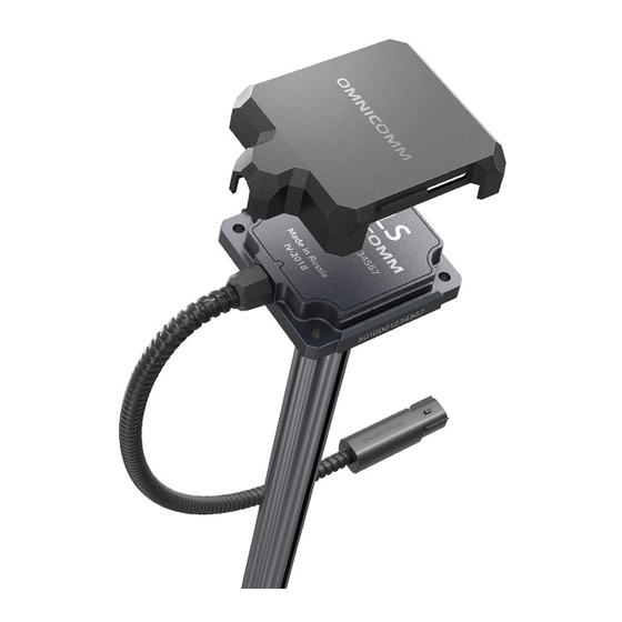
- Page 1 Omnicomm LLS 5 Fuel Level Sensor User Manual 02.10.2020...
-
Page 2: Table Of Contents
Installation and Connection Calibration Sealing Recommendations for the Assembly of the Fuel Sensors from 3 to 6 meters in length Fuel Level Sensor Installation Recommendations for Cylindrical Fuel Tanks Appendix. List of equipment for Omnicomm LLS fuel level sensors installation... -
Page 3: General Information
General information This User Manual is designed for Omnicomm LLS 5 fuel level sensors. Omnicomm LLS 5 is a fuel level sensor with RS-232 and RS-485 interfaces. While carrying out installation, observe the safety rules and regulatory requirements for this type of work. -
Page 4: Technical Specifications
Technical Specifications Technical Specifications Parameters Value Measurement range, mm 0…700, 1000, 1500, 2000, 2500, 3000 REF-channel length, mm - for sensors of 700, 1000 mm length - for sensors longer than 1500 mm Limit of the allowed basic level ± 0,5 (when working with fuel for which the measurement error, % calibration was carried out or after filling the tank to the full when changing the type of fuel) - Page 5 Technical Specifications Parameters Value Atmospheric pressure, kPa From 84 to 107 Maximum relative humidity at 25 °С (without moisture condensation), % Ingress protection rating IP69k Operating mode Continuous Internal filter size From 0 to 30 Measurement time period, s Overall dimensions, mm 87.3 x 83.5 x (21 + length of the measuring probe) Weight, kg Not more than 2...
-
Page 6: Preparation
Preparation Preparation Fuel Tank Preparation 1. Select the location for Omnicomm LLS sensor installation, taking into account the following requirements: The installation location should be as close to the geometric center as possible and be placed at the deepest level of the tank:... - Page 7 Preparation The mounting hole diameter depends on the material of the tank: ø 4 mm – for metal tanks with wall thickness over 3 mm (cut M5 thread) ø 7 mm – for plastic and metal tanks with wall thickness up to 3 mm (for rivets) ø...
-
Page 8: Sensor Preparation
Preparation Sensor Preparation 1. Cut the sensor measuring part according to the following recommendations: The length of the sensor measuring probe should be 20mm less than the depth of the tank. The REF channel must be at least 100 mm shorter that the measuring part of the sensor. -
Page 9: Setting
Setting Setting Firmware update is only done via RS-485 interface connection. Connect the sensor to a PC. Connect the Omnicomm LLS 5 sensors according to the diagram: Run the Omnicomm Configurator program on your PC. - Page 10 Setting Omnicomm Configurator (PC): The fuel level value is displayed without filtering.
-
Page 11: Full/Empty" Calibration
Setting “Full/Empty” Calibration 1. Fill the measuring container with fuel 2. Immerse the Omnicomm LLS sensor in the fuel to the full length of the measuring piece 3. Wait for the green indicator “Stabilized” to appear. Press the button “Full” to record the value corresponding to a full tank 4. -
Page 12: Omnicomm Lls 5 Sensor Setting
When operaеing a vehicle with insufficient fuel level in the tank, auto-tuning cannot be performed. “Network address” (1 to 254) – set the network address for the Omnicomm LLS fuel level sensor. When several sensors are connected to one external device, they should have unique network addresses. -
Page 13: Installation And Connection
Installation and Connection “Data output interval” (1 to 255 seconds) – set the automatic data output interval The automatic data output mode may be used with no more than one Omnicomm LLS 5 sensor connected to one interface. “Heavy exploitation conditions” - turn on for additional filtering of measurement values that takes into account severe operating conditions. - Page 14 Installation and Connection Functions of the mounting cable wires Name of signal Wire Color RS-485 A Orange-white RS-485 B White-blue RS-232 Tx Pink RS-232 Rx Gray +V Power Brown Ground White 4. Connect the fuse holder to the LLS sensor power cable (brown wire) in close vicinity to the vehicle power supply circuit...
-
Page 15: Calibration
Calibration of the fuel tank is necessary to verify the conformity of the digital code issued by the Omnicomm LLS 5 sensor to the fuel volume in a particular fuel tank. Calibration of the fuel tank is performed by refueling up the tank – from empty to full, with a certain refueling interval, and recording the Omnicomm LLS 5 sensor readings in the cali-bration table. - Page 16 Calibration If the sensor reading column is not displayed, press the “Add sensor” button. Select the type of sensor. Specify the network address set for the sensor during the setup.
- Page 17 20 10. Press the “Finish calibration” button 11. Save the calibration table in a calibration file (.ctb), Omnicomm Online (.xml) file, in the Terminal or in the Indicator, by pressing the “Export” button When performing the calibration table export to the Omnicomm Online (.xml) file, the “Export”...
-
Page 18: Sealing
Sealing Sealing For Omnicomm LLS sensors, the sensor housing is sealed with a casing-seal and a connector: 1. Install the casing-seal on the sensor housing 2. Place the pins in the grooves of the casing-seals, making sure that they are positioned... - Page 19 Sealing 1. Join Omnicomm LLS 5 connector to the mounting cable until it clicks 2. Run the flexible part of the seal through the connectors 3. Run the flexible part of the seal through the hole in the seal body 4.
-
Page 20: Recommendations For The Assembly Of The Fuel Sensors From 3 To 6 Meters In Length
Recommendations for the Assembly of the Fuel Sensors from 3 to 6 meters in length Recommendations for the Assembly of the Fuel Sensors from 3 to 6 meters in length 1. Take the fuel level sensor and the extension of the measuring part from the package 2. -
Page 21: Fuel Level Sensor Installation Recommendations For Cylindrical Fuel Tanks
When installing the fuel sensor onto cylindrical fuel tanks with the diameter 420…710 mm it is necessary to purchase a set of gaskets for round fuel tanks. Replace the gaskets and the bolts provided with the LLS 5 with gaskets and screws for the round fuel tank. - Page 22 Fuel Level Sensor Installation Recommendations for Cylindrical Fuel Tanks The installation sequence of Omnicomm LLS 5 fuel level sensors: The sensor's cable should align with the direction of the vehicle or shall be located on the long side of the fuel tank.
- Page 23 Fuel Level Sensor Installation Recommendations for Cylindrical Fuel Tanks...
-
Page 24: Appendix. List Of Equipment For Omnicomm Lls Fuel Level Sensors Installation
Appendix. List of equipment for Omnicomm LLS fuel level sensors installation Appendix. List of equipment for Omnicomm LLS fuel level sensors installation № Name Quantity Bimetal core drill ø35 mm Core drill shank Metal drill ø7 mm or ø4 mm... - Page 25 Appendix. List of equipment for Omnicomm LLS fuel level sensors installation № Name Quantity Seal-tie...
- Page 26 www.omnicomm-world.com...
Need help?
Do you have a question about the LLS 5 and is the answer not in the manual?
Questions and answers