SureCall Fusion2Go OTR Quick Setup Manual
Hide thumbs
Also See for Fusion2Go OTR:
- User manual (14 pages) ,
- Quick setup manual (2 pages) ,
- Quick installation manual (2 pages)
Table of Contents
Advertisement
Quick Links
BEFORE INSTALLATION
Select a location on your vehicle for the outside antenna.
Multiple placement and height configurations are available to
achieve the best configuration for your specific vehicle needs.
The antenna can be mounted on any truck, with or without an
existing antenna mounting point. For vehicles without built-in
mounting points, the antenna uses a 3/8 x 24 thread mount
designed to accommodate many available 3rd party CB mounts.
A 2-clamp mounting bracket is provided for use on a mirror rail
or other existing vehicle rails.
Additionally, an extension pole is also provided. Note, it is
needed only to achieve the clearance requirements for the
antenna specified below.
Keep in mind, the antenna mounting location should:
(a) allow the antenna to extend above the metal cab (b) be
at least 6 inches away from any windows (c) provide at least
a 12-inch radius clear of obstructions and other radiating
elements, such as a radio antenna.
Thread glue is provided with the antenna. It should be applied
at each threaded connection only after you have confirmed the
proper height configuration as the glue will make the connection
permanent.
A "soft installation" should first be performed by assembling the truck antenna (WITHOUT GLUE)
and routing the cable through an open window. After completing the remaining installation steps
and successful operation is verified, proceed with permanent installation.
STEP 1.
INSTALL THE OUTSIDE ANTENNA
Once you have determined the mounting location, assemble the antenna
parts by routing the cable through the mast extension (if used) and
through the cable exit adapter.
If using the provided mounting bracket, we recommend installing
the spring base and mounting bracket before adding the remaining
assembly.
INSTALL MOUNTING BRACKET
Secure bracket to vehicle rail as shown using
provided hardware. Secure all four bolts in place
and secure with a wrench.
SECURE THE ASSEMBLED ANTENNA TO THE MOUNTING BRACKET
Assemble the spring base and mounting bracket by placing the threads
through the opening of the mounting bracket as shown in the illustration.
Use the provided washers on the bottom of the bracket opening
then add the nut to bottom of the thread to secure in place. Once
complete, connect the assembled antenna and the spring base.
ROUTE CABLE
Route cable from outside to the inside of the cabin behind a door seal
where your booster will be located. If additional cable length is needed,
optional 5 ft extension cable has been provided.
STEP 2.
INSTALL INSIDE ANTENNA
32 in.
Identify a location for the inside antenna on or
height
near your front dashboard that is: (1) Within 2-3
feet of typical cell phone location, (2) at least 8
inches (20cm) from cellular devices, and (3) at
least 4 inches (10cm) from any metal.
Peel Velcro backing off the inside antenna and
apply to a clean, dry surface in your chosen
16 in.
location.
height
STEP 3.
PLACE BOOSTER AND CONNECT CABLES
Select a well-ventilated location for the booster that
is away from excessive heat, direct sunlight, and
moisture. We often suggest installing the booster
beneath a seat or inside the front console.
Connect the cable from the outside antenna to the
With mast
Without mast
extension
extension
connection marked OUTSIDE. Then, connect the
cable from inside patch antenna to the connection
marked INSIDE. Hand tighten the connections and
secure/stow any loose cable.
STEP 4.
CONNECT TO POWER
Once antenna connections are complete, connect the DC power cord connector to the signal
booster. The Power LED on the signal booster will illuminate to indicate it is receiving power
and is ready for use.
Place a call in a location where you previously experienced poor cell service and confirm that
your phone is receiving a boosted signal.
Antenna
Cable
Mast
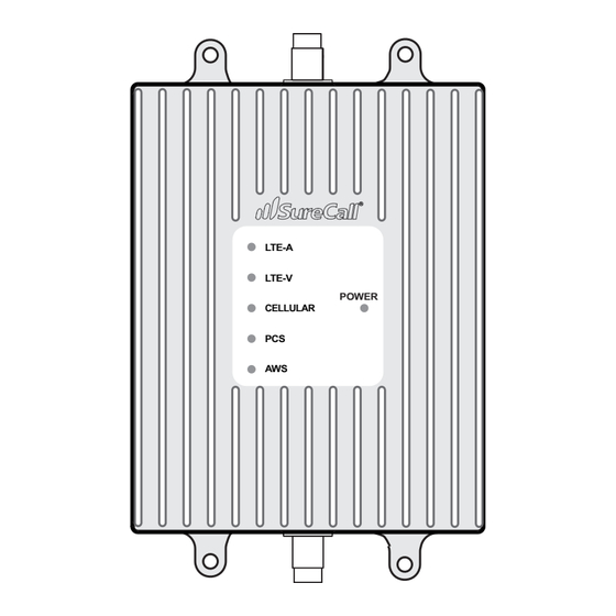
LTE-A
LTE-V
extension
CELLULAR
PCS
(optional)
AWS
VERIFY YOUR SYSTEM IS WORKING
Cable exit
adapter
Normal operation is indicated by Green LEDs (flashing or solid). In the event Red LEDs appear,
antenna adjustments may be needed. Review the following potential causes:
Spring base
•
Verify the two antennas have sufficient separation/isolation from the other another.
•
Verify the outside antenna has sufficient clearance above any metal objects and has at least
Mounting
12 inch radius from other radiating elements, such as a radio antenna.
bracket
•
Consider: Resolving the issue may require moving the outside antenna further from the
vehicle cabin and/or increasing the vertical placement of the outside antenna. If you have not
used the optional mast extension, try adding it to achieve additional separation.
© 2022, SureCall, Inc. All rights reserved
Inside patch
antenna
To OUTSIDE antenna
To INSIDE patch antenna
Outside
antenna
DC power
POWER
supply
DC power
jack
Inside patch
antenna
|
48346 Milmont Drive
|
Fremont, California 94538 USA
Have questions?
We have answers! Reach out to our US-based support team:
Call:
1-888-365-6283
Email:
support@surecall.com
Visit:
www.surecall.com/support to download the user manual for:
» Detailed setup instructions » Troubleshooting tips » Warranty information
3-Year Warranty
Thank you for your SureCall purchase. Please take the time to register your new product at
www.surecall.com/activate (US) or www.surecall.com/CA/activate (Canada)
SureCall warranties its products for three years from the date of purchase against defects in workmanship and/or
materials.
Products returned by customers must be in their original, un-modified condition, shipped at the customer's
expense in the original or protective packaging with proof-of-purchase documentation enclosed and a Return
Merchandise Authorization (RMA) number printed clearly on the outside of the shipping container. RMA numbers
are obtained by contacting Customer Support.
This warranty does not apply to any product determined by SureCall to have been subjected to misuse, abuse,
neglect, or mishandling that alters or damages the product's physical or electronic properties.
For complete warranty text, including limitations and liability, see the Fusion2Go OTR full user manual, available
online.
LEDS
Place a call in a location you have previously experienced poor signal and confirm that your phone
is receiving a boosted signal. Normal operation is indicated by Green LEDs (both flashing and
solid). In the event Red LEDs appear, antenna adjustments may be needed.
Color
Condition
Indication
Green
Solid
Indicates normal operation.
Green
Flashing
Normal operation. Indicates that Automatic Gain Control (AGC) is self-adjusting
due to over-signal or antenna proximity.
Red
Flashing
Indicates issues caused by overpowering or oscillation. Adjustment of your
outside antenna placement is likely needed. Verify that it has sufficient sepa-
ration from the inside antenna, as well as, any potentially interfering objects or
antennas
Troubleshooting
Problem
Resolution
Signal booster has
Verify that the Power LED is ON.
no power
Connect the power supply to an alternate power source.
Verify that the power source is operational and the fuse is intact.
If it remains OFF, contact tech support at: 1-888-365-6283 or support@surecall.com
After completing
Verify that cable connections are tightly fitted to the booster.
installation, signal
Try further separating the antennas.
coverage has not
Note: Bars are not always a reliable measure of signal. The best way to confirm signal
improved
coverage is the ability to place and hold a call.
Advertisement
Table of Contents

Related Manuals for SureCall Fusion2Go OTR


Summary of Contents for SureCall Fusion2Go OTR
- Page 1 This warranty does not apply to any product determined by SureCall to have been subjected to misuse, abuse, proper height configuration as the glue will make the connection marked INSIDE.
- Page 2 20 dB (Automatic) ➌ ➌ Input Impedance: 50 Ω 48346 Milmont Dr, Fremont, CA 94538 Noise Figure: ≤ 5 dB ➏ 1-888.365.6283 | support@surecall.com | www.surecall.com DC Power: 6- 15V ➋ ➋ Maximum Output Power: 1 Watt EIRP ➎ ➎ Power Consumption: ≤...
Need help?
Do you have a question about the Fusion2Go OTR and is the answer not in the manual?
Questions and answers