Table of Contents
Advertisement
Quick Links
EU
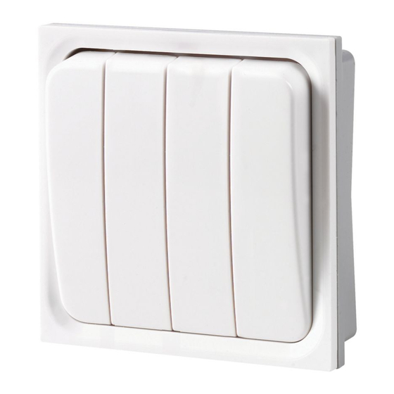
xComfort F94XX Control Buttons
Scope of delivery
F9400
Surface mounting plate
Typical Application
F9400 Surface
mounting plate
Mounting Frame
Style
Surface Mounting Frame
Copa Flush 2 Module
Style
Premera Flush 2 Module
Eaton Industries (Austria) GmbH, A-3943 Schrems
www.eaton.eu/documentation
F9401
1 Gang Button
+
+
F940x Button module
Decorative Plastic
List No List
F9400
CP902WH
CP902BM
C902
CP902GL
CP902SL
CP902BL
CP902GY
List No List
P902
White moulded only - no cover
plate needed
F9402
2 Gang Button
CP902xx Clip on plate
Metal Plate
Finish
List No
White
CP902SS
Black Matt
CP902HP
Gold Metalic
CP902SB
Silver Metalic
CP902PB
Blue Metalic
Grey
Finish
List No
White moulded only - no cover
plate needed
1
F9404
4 Gang Button
MRF
Min. Version 2.0
R
F
Min. Version 3.5
T=-25°C - +70°C
T=+5°C - +40°C
IP20
Finish
Stainless Steel
Highly Polished
Satin Bronze
Polished Brass
Finish
MA-MEM_F940X.qxd/01.2015c
IL019061ZU / 136211172
Advertisement
Table of Contents

Related Manuals for Eaton xComfort F94 Series


Summary of Contents for Eaton xComfort F94 Series
- Page 1 Style List No List Finish List No Finish Premera Flush 2 Module P902 White moulded only - no cover White moulded only - no cover plate needed plate needed Eaton Industries (Austria) GmbH, A-3943 Schrems MA-MEM_F940X.qxd/01.2015c www.eaton.eu/documentation IL019061ZU / 136211172...
- Page 2 P9400 Flush P9400 Surface Mounted on Mounted on wall box flat surface Click P9400 Surface /Flush mount Flush mount Premera with clip on cover Frame e.g.P902 Screw caps if required 4 x Click...
- Page 3 P9400 Surface / Flush mounting frame Prise off „Clip on“ Insert screwdriver to release Cover module from surface plate Flush mounting frame e.g. P902 Remover screw cap discs, if fitted, along with mounting screws to release flush plate from wall box and allow access to battery at rear of module Mounting...
- Page 4 Eaton RF System Basic Mode Quick Reference Symbols: Sensors: Actuators: Link Device Unlink Device (selectively) Reset actuator (all settings & connections) Manual Operation LED is on LED flashes 5 times LED is on Lamp (LED) is on Lamp (LED) is on 1.
- Page 5 Assign a channel of the binary input in push button mode 1. Press the configuration button on the binary input (the mains supplied version requires a screwdriver) for selecting the mode, push button mode is Mode 1, LED flashes 1x for Mode 1 2.
- Page 6 3. Manual operation: Manual operation of switching actuator, dimming actuator 1. Press the configuration pushbutton with a screwdriver longer than 2 sec => actuator enters manual mode for 10 sec, the LED flashes fast 2. Press the configuration pushbutton with a screwdriver for less than 0.5 sec => Lamp (LED) is on 3.
- Page 7 5. Configure a router CROU-00/01 in Basic-Mode 1. If there is no RF connection between push button and an actuator, an additional router can be configured to extend range. 2. To assign a push button to a router:- a) Press the router configuration pushbutton with a screwdriver for less than 0.5 sec =>...
- Page 8 Declaration of Conformity We, EATON Industries (Austria) GmbH 3943 Schrems, Eugenia 1 Austria declare that product (family) Eaton - MEM switch module, F9401, F9402, F9404 (the declaration of conformity applies to all listed types within our actual product catalog) provided that it is installed, maintained and used in the application intended for, with respect to the relevant manufacturers instructions, installation standards and “good engineering practices”...
Need help?
Do you have a question about the xComfort F94 Series and is the answer not in the manual?
Questions and answers