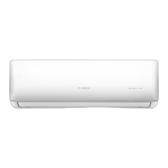
Bosch Climate 5000 Series Installation Instructions Manual
24 volt interface
Hide thumbs
Also See for Climate 5000 Series:
- User manual ,
- Service manual (106 pages) ,
- Installation instructions manual (60 pages)
Table of Contents
Advertisement
Installation Instructions
24 Volt Interface
208/230V~60Hz 1Ph & 115V~60Hz 1Ph
Climate 5000 Series
WARNING:
Installation must be performed by a licensed
contractor, and per the instructions in the
installation manual. Improper installation can
cause water leakage, electrical shock, or fire.
In North America, installation must
be performed in accordance with the
requirement of NEC (National Electric Code)
and CEC (Canadian Electric Code) by licensed
and qualified personnel only.
Only contact a licensed contractor for repair
or maintenance of this unit.
Advertisement
Table of Contents

Summary of Contents for Bosch Climate 5000 Series
- Page 1 Installation Instructions 24 Volt Interface 208/230V~60Hz 1Ph & 115V~60Hz 1Ph Climate 5000 Series WARNING: Installation must be performed by a licensed contractor, and per the instructions in the installation manual. Improper installation can cause water leakage, electrical shock, or fire.
-
Page 2: Application
Installation Instructions Bosch Climate 5000 Series 24 Volt Interface (06.2022) -
Page 3: Table Of Contents
5 Applications 5.1 Application 1 5.2 Application 2 6 Control Logic 6.1 Connector 6.2 Mode Setting 6.3 Fan Speed Setting 7 Dip Switch Confi guration 7.1 Dip Switch Defi nitions 8 Error Codes Bosch Climate 5000 Series 24 Volt Interface (06.2022) -
Page 4: Key To Symbols And Safety Instructions
This product can expose you to chemicals including Lead and Lead components, which are known to the State of California to cause cancer and birth defects or other reproductive harm. For more information go to www. P65Warnings.ca.gov. Bosch Climate 5000 Series 24 Volt Interface (06.2022) -
Page 5: Dimensions
283mm (11.1") 63mm (2.5") Figure 1 3 Clearances This interface must be installed indoors in an area free from drips and moisture. > 150mm > 150mm (5.9") (5.9") Right Wrong Figure 2 Bosch Climate 5000 Series 24 Volt Interface (06.2022) -
Page 6: Installation
Refer to indoor connective wires size INTERFACE vertically and fasten the back plate to the wall with 3 screws (M4 x20) and anchors (see Fig. 4). 18AWG (minimum) Y/W/G/G1/G2/G3/Dry 24AWG (minimum) Table 3 Bosch Climate 5000 Series 24 Volt Interface (06.2022) -
Page 7: Applications
Minisplit 12kBTU Universal Ducted 230V Ducted BMS500-AAU018-1AHDXB 8-733-953-104 Minisplit 18kBTU Universal Ducted 230V BMS500-AAU024-1AHDXB 8-733-953-105 Minisplit 24kBTU Universal Ducted 230V Table 4 Wall Mounted (Sizes 9K~36K) Cassette (Sizes 9K~24K) Ducted (Sizes 9K~24K) Bosch Climate 5000 Series 24 Volt Interface (06.2022) - Page 8 Please connect thermostat G to 24V interface G as default. Make sure the power supply is correct. For Wall Mounted unit, the up-down swing louver and the display on/off function is available with the wireless remote control. Bosch Climate 5000 Series 24 Volt Interface (06.2022)
- Page 9 Minisplit 60kBTU Universal Ducted 230V Table 5 Cassette (Sizes 36K~48K) Ducted (36K~60K) Wiring Thermostat Figure 7 Please connect thermostat G to 24V interface G as default. Make sure the power supply is correct. Bosch Climate 5000 Series 24 Volt Interface (06.2022)
-
Page 10: Control Logic
Must be switched to ON before using the system. Dip Switch 2-1 Used for selection of the system: Cooling Only or Heat Pump. SW2-1 Result Note Cooling only Heat pump Default Table 11 1 0 | Bosch Climate 5000 Series 24 Volt Interface (06.2022) - Page 11 SW3-2 Result Note Default Table 14 Dip Switch 4-1 For factory test only. SW4-1 Note Default Table 15 Dip Switch 4-2 For factory test only. SW4-2 Note Default Table 16 | 11 Bosch Climate 5000 Series 24 Volt Interface (06.2022)
-
Page 12: Error Codes
Compressor drive malfunction Compressor low-pressure protection Module boot mode and indoor running mode for power off Module and indoor unit communication malfunction Module and outdoor unit communication malfunction Table 17 1 2 | Bosch Climate 5000 Series 24 Volt Interface (06.2022) - Page 13 Installation Instructions NOTES: | 13 Bosch Climate 5000 Series 24 Volt Interface (06.2022)
- Page 14 Installation Instructions NOTES: 1 4 | Bosch Climate 5000 Series 24 Volt Interface (06.2022)
- Page 15 Installation Instructions NOTES: | 15 Bosch Climate 5000 Series 24 Volt Interface (06.2022)
- Page 16 United States and Canada Bosch Thermotechnology Corp. 65 Grove St. Watertown, MA 02472 Tel: 866-642-3198 Fax: 603-965-7581 www.bosch-thermotechnology.us BTC 769103310 B / 06.2022 Bosch Thermotechnology Corp. reserves the right to make changes without notice due to continuing engineering and technological advances.


Need help?
Do you have a question about the Climate 5000 Series and is the answer not in the manual?
Questions and answers