Table of Contents
Advertisement
Quick Links
https://appliancetechmanuals.com
Technical Service Guide
December 2020
2020 Stainless Steel Tub Dishwasher
CDT800P2N3S1
CDT805M5N3S5
CDT805P2N3S1
CDT845M5N3S5
CDT845P2N3S1
CDT845P3N3D1
CDT845P4N3W2
DDT700SBN3TS
DDT700SFN3DS
DDT700SGN3BB
DDT700SGN3WW
DDT700SMN3ES
DDT700SSN3SS
DDT700SYN3FS
GDF565SSN3SS
GDF645SGN3BB
GDF645SGN3WW
GDF645SMN3ES
GDF645SSN3SS
GDP645SYN3FS
GDP665SYN3FS
GDT565SSN3SS
GDT645SFN3DS
GDT645SGN3BB
GDT645SGN3WW
GDT645SMN3ES
GDT645SSN3SS
GDT645SYN3FS
GDT665SBN3TS
GDT665SFN3DS
GDT665SGN3BB
GDT665SGN3WW
GDT665SMN3ES
GDT665SSN3SS
GDT665SYN3FS
PDP715SBN3TS
PDP715SYN3FS
PDT715SBN3TS
PDT715SFN3DS
PDT715SMN3ES
PDT715SYN3FS
QDP555SBN3TS
QDP555SYN3FS
31-9345
Advertisement
Table of Contents

Related Manuals for Haier GE CDT800P2N3S1


Summary of Contents for Haier GE CDT800P2N3S1
- Page 1 https://appliancetechmanuals.com Technical Service Guide December 2020 2020 Stainless Steel Tub Dishwasher CDT800P2N3S1 CDT805M5N3S5 CDT805P2N3S1 CDT845M5N3S5 CDT845P2N3S1 CDT845P3N3D1 CDT845P4N3W2 DDT700SBN3TS DDT700SFN3DS DDT700SGN3BB GDT665SMN3ES GDT565SSN3SS DDT700SGN3WW GDT645SFN3DS GDT665SSN3SS DDT700SMN3ES GDT645SGN3BB GDT665SYN3FS DDT700SSN3SS GDT645SGN3WW PDP715SBN3TS DDT700SYN3FS GDT645SMN3ES PDP715SYN3FS GDF565SSN3SS PDT715SBN3TS GDT645SSN3SS GDF645SGN3BB GDT645SYN3FS PDT715SFN3DS GDF645SGN3WW GDT665SBN3TS...
-
Page 2: Safety Information
5. Locate the Warranty page. GE Appliances, a Haier Company Copyright © 2020 All rights reserved. This service guide may not be reproduced in whole or in part in any form without written permission from GE Appliances, a Haier Company. – 2 –... -
Page 3: Table Of Contents
https://appliancetechmanuals.com Table of Contents Safety Information ........................2 Warranty ............................2 Table of Contents ..........................3 Safety Requirements ........................6 Nomenclature ..........................7 Electrical Specifications ........................9 Operation and Cycle Information ....................10 Troubleshooting ..........................13 Flashing Lights ........................13 Will Not Start .........................13 Critical Errors ........................14 Component Locator Views ......................15 Front Control .........................15 Top Control ...........................15 Toe Kick Area ........................16... - Page 4 https://appliancetechmanuals.com Latch System ........................23 Latch Switch Diagnosis ......................23 Racks ............................24 Lower Rack ...........................26 Silverware Baskets .......................27 Third Rack (Some Models) ....................27 Silverware Wash ........................28 Door ............................28 Inner Door Vent Cover ......................31 Front Control Console ......................32 User Interface (UI) ........................33 Top Control User Interface (UI) .....................33 Outer Door Panel ........................34 Door Hinges ..........................34 Pocket Handle ........................34...
- Page 5 https://appliancetechmanuals.com CSM (Current Sense Module) ....................49 Fill System ............................51 Water Level ...........................51 Pressure Switch ........................51 No Fill Diagnostics ........................53 Fill Funnel and Hose ......................54 Fill Valve ..........................54 Circulation System ........................55 Diagnostics ...........................56 No Circulation and Drain ......................57 Filtration ..........................58 Circulation Motor and Pump Assembly .................59 Pressure Diverter (Two Port) ....................60 Pressure Diverter (Four Port) ....................62 Pressure Diverter Switch ......................64...
-
Page 6: Safety Requirements
https://appliancetechmanuals.com Safety Requirements GEA Factory Service Employees are required to use safety glasses with side shields, safety gloves and steel toe shoes for all repairs. Prescription Safety Glasses Plano Type Safety Glasses Safety Glasses must be ANSI Z87.1-2003 compliant Cut Resistant Sleeve(s) Electrically Rated Glove and Dyneema®Cut Resistant Dyneema®... -
Page 7: Nomenclature
G D T 6 7 5 S S N 3 S S Brand Color G: GE BB: Black P: Profile Configuration DS: Black Slate Engineering Q: Haier D: Built-In ES: Slate Digit D: Adora FS: Fingerprint 0 - 99 Free Stainless Control Appearance... - Page 8 https://appliancetechmanuals.com The nomenclature breaks down and explains what the letters and numbers mean in the model number. Serial Number The first two characters of the serial number identify the month and year of manufacture. The letter designating the year repeats every 12 years. Example: GM123456S = April, 2019 Model and Serial Tag A: JAN...
-
Page 9: Electrical Specifications
https://appliancetechmanuals.com Electrical Specifications DC Voltage AC Voltage Turbidity Sensor: 5 VDC to LED, 10k ohms • Circulation Pump: 120 VAC, .8 amps to 3.8 LRA (Locked Rotor Amps), 8GPM @ 5PSI Thermistor Specifications • Drain Pump: 120 VAC, .3 to 5 ohms, .65 (in Turbidity Sensor) amps, ~70 second cycle Resistance Temperature... -
Page 10: Operation And Cycle Information
https://appliancetechmanuals.com Operation and Cycle Information This section of the guide provides details on segments of cycles, timing of cycles, temperature expectations, and cycling of the heater during the dry portion of a cycle. Auto Hot Start At the beginning of the main wash, the dishwasher checks the temperature of the water, and if it is below 90°F, then it will add up to 10 minutes of time to heat the water to 90°F by circulating the water while the heater is on. - Page 11 https://appliancetechmanuals.com Cycle Times (Estimated) NOTES: Cycle times will vary depending on options selected, incoming water temperature, and soil level (some models). • Incoming water temperature of 120°F to 140°F is recommended. • Circulation has built-in pauses (see Two Port Diverter and Pressure Diverter (Four Port) in the Circulation System section of this guide).
- Page 12 https://appliancetechmanuals.com Target / Max Temperature Limits Cycle Rinse Light Normal Auto Heavy 1-Hour Heater Algorithm, Dry Cycle Normal with Heated Dry Time Calrod Description (minutes) Calrod on Calrod Pulse - 2 minute on/1 minute off Calrod off - Cool Down Normal with Temp Boost or Steam/Sani Selected Calrod on Calrod Pulse - 1 minute on/1 minute off...
-
Page 13: Troubleshooting
https://appliancetechmanuals.com Troubleshooting This is an overview of diagnostic capabilities of the electronic control. The control features also allow retrieval of fault codes when Consumer Error Mode is initiated; operation of loads is achieved in Service Mode. Remove single mounting screw to Details on Consumer Error Mode and Service access the machine control Mode, as well as Service LED are located in the... -
Page 14: Critical Errors
https://appliancetechmanuals.com Critical Errors Critical errors will turn a cycle off and show a display alerting the consumer of a fault which will not allow the dishwasher to function or cause an undesirable condition. No Water Detected In the event the internal water level does not change, the cycle will be canceled, and the user interface (UI) will display the following: •... -
Page 15: Component Locator Views
https://appliancetechmanuals.com Component Locator Views Appearances may vary throughout this service guide. Some models do not have all features shown or may be different depending the model number. Front Control Front Console Vent Pocket Handle Outer Door Panel Top Control Display Pocket Handle Display Bar Handle... -
Page 16: Toe Kick Area
https://appliancetechmanuals.com Toe Kick Area Toe Kick Screws Water Valve Junction Box Insulation Toe Kick Panel Sump Side Tub Trim Third Rack Mounting Hardware High Drain Loop Hose Fill Hose Fill Funnel Offset Leg Hinge Arm Balance Cable Balance Roller Balance Spring –... -
Page 17: Back
https://appliancetechmanuals.com Back Heater Mounting Nuts High Drain Loop Hose Bottom Main Control Box Junction Box Level Leg Sump Water Valve Fill Hose High Drain Loop Hose Tub TCO (between motor and tub) – 17 –... -
Page 18: Sump (Top)
https://appliancetechmanuals.com Sump (Top) Diverter Diverter Check Ball Fine Filter Sump Ultra-Fine Filter and Basket Sump (Bottom) Sump Pressure Switch Turbidity Sensor Sump Latch Cam Floating Seal Circulation Pump Drain Pump Sump Latch Cam – 18 –... -
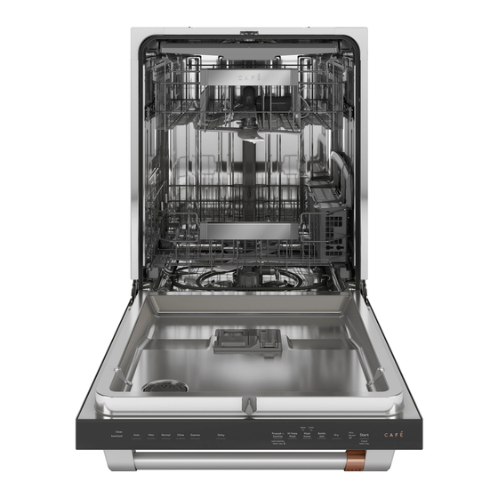
Page 19: Inside
https://appliancetechmanuals.com Inside Tub Trim Third Rack Upper Rack Main Conduit Silverware Basket Lower Rack Detergent Module Door Strike Appearances may vary throughout this service guide. Some models do not have all features shown or may be different depending the model number. –... -
Page 20: Tub And Structure
https://appliancetechmanuals.com Tub and Structure The Tub and Structure section of this guide will Toe Kick cover the toe kick, junction box, racks, leveling, door balance, gaskets, trim (some models), main The toe kick panel is a safety and decorative control board, door, door components, as well panel covering the machine area of the as the removing and separation of the screwless dishwasher. -
Page 21: Leveling Legs
https://appliancetechmanuals.com Leveling Legs Door Springs and Cables There are four leveling legs located on the base The spring is adjustable as it attaches to the rear rails of the dishwasher. of the leg base assembly. There are two holes in the leg and factory setting on a support screw. To access the level legs, remove the toe kick Higher connection on the rear frame on the leg and insulation (some models). -
Page 22: Tub Gasket
https://appliancetechmanuals.com To Remove Tub Gasket: Pull the gasket from the Tub Gasket retainer area. Tub Gasket Tub Gasket Installation 1. The center of the gasket has a mark which is placed pointing to the inside of the dishwasher. This position will orient the gasket wiper to face the inside of the dishwasher and to the inner door. -
Page 23: Latch System
https://appliancetechmanuals.com 4. Continue to push the gasket into the track To Replace the Door Latch / Switch Assembly to the bottom of the tub and extending the 1. Remove power to the dishwasher. gasket 2-inches to the center of the tub. 2. -
Page 24: Racks
https://appliancetechmanuals.com Tub Rollers Racks The tub rollers are attached to the tub with a Upper Rack screw in each roller. Two upper rack configurations are available, To Remove the Tub Rollers depending on the model: Wheels on Rails or Full Extension Rails. - Page 25 https://appliancetechmanuals.com Full Extension Rails Pull out 1/2-in. and slide the rail toward the front of the rack, releasing the rail from the rear tab. To remove the upper rack and full extension rails: 1. Extend to the full outward position. 2.
-
Page 26: Lower Rack
https://appliancetechmanuals.com Bottle Wash Components (Some Models) Lower Rack To remove the bottle wash components, remove Several lower racks are available with different the cover by releasing the clip at the bottom and tine configurations; consult the Owner’s Manual slide the cover to the right. for details on the lower racks. -
Page 27: Silverware Baskets
https://appliancetechmanuals.com Third Rack Brackets Silverware Baskets To remove the brackets, the dishwasher must be There are a variety of silverware baskets and removed from installation. configurations available. Consult the Owner’s Manual for silverware basket information. 1. Remove the basket and the frame. 2. -
Page 28: Silverware Wash
https://appliancetechmanuals.com Silverware Wash Door The door has DC voltage only and has a screwless appearance. The door contains a user interface (UI) board with all tactile switches on the board. Some models have a seven segment display (SSD); others have LED indicator lights. The door also houses the detergent module, bottom door seal and a venting system (see the Dry System section in this service guide). - Page 29 https://appliancetechmanuals.com 5. Locate the door balance cable and insert an 8. Slide the cable into the cable clip to prevent Allen wrench or tool formed into a hook (as the spring from disconnecting from the cable. shown below). CAUTION: If the cable is released, the spring and cable may become disconnected.
- Page 30 https://appliancetechmanuals.com 10. Standing in front of the dishwasher, open the door a few inches, then lift the door and hinge arms off of the offset leg. When installing the door onto the dishwasher, make sure the hinge pins located on the hinge arms are placed fully on the offset legs (both sides).
-
Page 31: Inner Door Vent Cover
https://appliancetechmanuals.com 4. Remove four T-25 Torx-head screws (two Inner Door Vent Cover each side) that secure the inner door to the hinge assemblies. The inner door vent cover must be removed on front control models (with passive vent) to allow the front control console to be removed from the inner door. -
Page 32: Front Control Console
https://appliancetechmanuals.com Front Control Console Removal To Reassemble the Door 1. Remove the door and separate the inner and 1. Place the outer panel face down on a outer door panels. protected surface. 2. Remove the vent cover from the inner door. 2. -
Page 33: User Interface (Ui)
https://appliancetechmanuals.com User Interface (UI) Top Control User Interface (UI) All user interfaces (UI's) are cap (capacitance) The top control user interface (UI) come as an touch. There are no buttons, light pipes or assembly, including the top console, UI and sealing components. -
Page 34: Outer Door Panel
https://appliancetechmanuals.com Outer Door Panel Pocket Handle Components Some models have a pocket handle mounted to the outer door panel. Lens Bar Handle Handle Screws Handle Brackets Hinge Screws Hinges To remove the pocket handle, remove seven 1/4- Badge in. hex-head screws. Bar Handle The bar handle is attached to the outer door panel. -
Page 35: Inner Door Panel
https://appliancetechmanuals.com Inner Door Panel Door Strike Stainless Steel (SS) Door Attach Strips Attachment strips are used to help secure the inner and outer door panels. Console Side Attach Strip Side Attach Screws (T15 Torx) Strip With the user interface (UI) and console (pocket handle on front control models) removed, there Side Attachment Strip(s) Removal is clear access to the 1/4-in. -
Page 36: Vent Parts
https://appliancetechmanuals.com Power Dry System Removal Vent Parts 1. Remove the inner door vent cover. Front Control Model (GDF565SSNxSS and 2. Disconnect the wire harness from the fan to GDT565SSNxSS) the user interface (UI) control. Model GDF565 and GDT565 have a passive vent through the control panel. -
Page 37: Detergent Dispenser
https://appliancetechmanuals.com Detergent Module Removal Detergent Dispenser 1. Remove power to the dishwasher. 2. Remove and separate the door. 3. Remove the EPS cover. The double backed tape is used to secure and is reusable. When reinstalling the EPS cover, the UP indicator must be toward the top of the door. -
Page 38: Sump Module
https://appliancetechmanuals.com Two Port Diverter Sump Module The ultra-fine filter is a twist lock design and consumer cleanable. To remove, turn counter- clockwise (CCW). Four Port Pressure Diverter The fine filter is secured by the ultra-fine filter and two tabs. To remove, remove the ultra-fine filter and lift up on the front, allowing the back to slide out of the tabs. - Page 39 https://appliancetechmanuals.com Sump Latch Cams With the cam in the unlatched position and the lock tab exposed, the cam can be removed or Sump latch cams twist and lock the sump into replaced as needed by sliding it away from the place, they are cammed for easy removal.
- Page 40 https://appliancetechmanuals.com Sump Module Removal 7. Remove the main conduit (see the Circulation System section of this service 1. Remove power to the dishwasher. guide). 2. Remove the upper and lower racks. 8. Loosen the high drain loop hose clamp (1/4- in.
- Page 41 https://appliancetechmanuals.com 11. Unlatch three sump latches. All three 14. Disconnect the circulation pump wiring, drain pump wiring and flood switch wiring. latches can be reached from the front of the dishwasher in most installations. If the dishwasher does not have the legs extended; the dishwasher may have to be removed from its installed position.
-
Page 42: Sump Gasket
https://appliancetechmanuals.com 3. Press firmly into place, using both hands to Sump Gasket push down on the sump module. Stressing or softening the gasket ribs (pressing the ribs against a hard surface, see below) will make a new gasket seat easier. Lubricating with a small amount of rinse agent or water will also ease installation. -
Page 43: Electronic Controls
https://appliancetechmanuals.com Electronic Controls The main control board is located under the dishwasher. It is supplied 120 VAC from the consumer's home. Outputs include 120 VAC to the heating element, wash and drain motors. The control also supplies 13.5 VDC to the fill system, door switches, turbidity sensor (some models), the user interface (UI) board and detergent module in the door. -
Page 44: Fault Codes
https://appliancetechmanuals.com Fault Codes Fault Load to Control Timeout / Notes Code Communication Error with UI Verify harness connections between UI board and MC Board board. High Water Temperature Check thermistor, harness and connectors. Check to see if the pressure sensor is plugged in, if so, then most likely the pressure sensor is out of range, Water Level Sensor Invalid thus replace the pressure sensor. - Page 45 https://appliancetechmanuals.com Fault Load to Control Timeout / Notes Code Check that the thermistor harness is plugged in. Check Dry Heater Thermistor Error - Out that the terminals are not bent inside the connector of Range Low housing. Clear faults and cycle power to unit. If fault reoccurs Heater Relay Stuck on Fault within 60 seconds of power up, replace MC board.
-
Page 46: User Interface (Ui) Diagnostics
https://appliancetechmanuals.com User Interface (UI) Diagnostics Consumer Error Mode No display or LED’s will light. To Enter Consumer Error Mode: With the dishwasher in Standby Mode (not running a Check for 120 VAC entering the main control. If cycle), press and hold the Cycle Select or furthest no volts are found, check the home breaker. -
Page 47: Demo Mode
https://appliancetechmanuals.com Demo Mode Appearances may vary. Some models do not have all features shown, or may be different depending the model number. CDT800 CDT805 CDT845 Demo Mode To enter Demo Mode, disconnect power to dishwasher for 30 seconds and reconnect power. Press and hold “Auto”... -
Page 48: Service Mode
https://appliancetechmanuals.com Diagnosing Electronic Control Boards Service Mode Entering Service Mode Diagnosing the main control and user interface (UI) control are covered in this section. Many NOTE: Entering Service Mode resets the CSM. components can be checked from the main control, which can be accessed with the door The dishwasher must be in Consumer Error Mode on or removed if needed. -
Page 49: Csm (Current Sense Module)
CSM (Current Sense Module) A CSM is a protective device that is part of GE, Profile, Haier, Café, Adora and Monogram Dishwashers and located on the main control board. This device is designed to trip if current leakage to ground is above 20mA ±... - Page 50 https://appliancetechmanuals.com Top Side of Main Control 6. Pull down on the bottom cover at the front of the control box. While pulling down on the front of the bottom cover, slide the cover forward to clear the back lip and junction box bracket.
-
Page 51: Fill System
https://appliancetechmanuals.com Fill System The dishwasher has a fill volume of approximately Water Level .83 gallons of water and is a DC volt circuit. The water valve is rated at 13.5 VDC, resistance is To check for proper water level, place the 32 ohms and has a flow rate of .83 GPM. - Page 52 https://appliancetechmanuals.com Below are some of the new actions the control The consumer is directed to turn water supply off can monitor and react to with different situations. and call for service. Testing the Pressure Sensor: To verify the No Water Detected: In the event the internal water level does not change, the cycle will be pressure sensor is receiving power, remove the canceled, and the user interface (UI) will display...
-
Page 53: No Fill Diagnostics
https://appliancetechmanuals.com No Fill Diagnostics Dishwasher not filling Are any fault codes displayed? Enter Service No repair needed, Mode, fill test (60 second possible home water fill) Does it fill? pressure fluctuation Is the fill level correct? Check for house Is water supply Check for plumbing fault, kinked fill Replace... -
Page 54: Fill Funnel And Hose
https://appliancetechmanuals.com Fill Funnel and Hose Fill Valve The fill funnel is located on the left side of the Water Valve Removal dishwasher tub and must be removed from 1. Remove power to the dishwasher. installation to gain access. Remove by turning the mounting nut counter-clockwise (CCW) from 2. -
Page 55: Circulation System
https://appliancetechmanuals.com Circulation System With only .83 gallons of water, filtration is the start of improved performance. Water is cleaned through the fine and ultra-fine filters before it enters the main pump. Water must also flow through the Piranha Hard-Food Disposal and finally into the wash pump assembly. Clean filtered water then flows into the diverter system which directs it to either the lower spray arm or mid spray arm and upper sprayer. -
Page 56: Diagnostics
https://appliancetechmanuals.com 7. The clear door has a latch strike. When Diagnostics pushed into the latched position, it will activate the door switch assembly. The Clear Door Diagnostic Tool dishwasher may not start if the clear door is installed to low. The Clear Door (Part #: WX05X20002) provides technicians with a tool to accurately diagnose 8. -
Page 57: No Circulation And Drain
https://appliancetechmanuals.com No Circulation and Drain Circulation and Drain Pumps will not run Remove Sump Module to check the AC wire harness Access main control, place dishwasher in Service Mode, run circulation and drain tests. . Check for 120 VAC on connector J703 pin 3 (OX) to pin 4 Open (CX) for circulation pump and pin 1 (NX) to pin 2 (YX). -
Page 58: Filtration
https://appliancetechmanuals.com The fine filter water path is shown below. Water Filtration passes through the fine filter and flows on the outside of the ultra-fine filter; passes through the Good filtration is key to good wash performance. turbidity sensor and into the circulation pump. The ultra-fine filter is consumer removable with a twist lock design. -
Page 59: Circulation Motor And Pump Assembly
https://appliancetechmanuals.com Use the flat-blade screw-driver to remove the Circulation Motor and Pump Assembly floating seal from the sump, using care not to damage the inside sealing surface. The circulation motor is a DC brushed motor; it has onboard AC to DC rectification. Resistance cannot be properly checked on this motor because of the rectifier and diodes inside the motor shield. -
Page 60: Pressure Diverter (Two Port)
https://appliancetechmanuals.com Clamp Removal Tip: Use a small screw-driver Pressure Diverter (Two Port) inserted into the ear of the clamp and move the handle back and forth to loosen the clamp. The The presssure diverter (two port) is the key clamp can be removed and discarded when the component which allows low water use, by component is removed. - Page 61 https://appliancetechmanuals.com • The wash pump turns on, water flows to the • The wash pump cycles on, and water lower spray arm, and the check ball blocks pressure keeps the check ball positioned to the rear port or upper spray conduit. The block water entering the lower spray arm.
-
Page 62: Pressure Diverter (Four Port)
https://appliancetechmanuals.com Two Port Diverter Removal Pressure Diverter (Four Port) The diverter top may be removed by removing one 1/4-in. hex-head screw and pressing in on the locking tab and turning counter-clockwise (CCW) to remove. Removing the top will expose the diverter check ball. The pressure diverter (four port) is the key component which allows lower water use, by alternating water to the:... - Page 63 https://appliancetechmanuals.com The diverter plate may be lifted out of the diverter Pressure Diverter Removal body. The diverter body is molded into the sump. The diverter top may be removed by pressing in on the locking tab and turning counter-clockwise (CCW) to remove. Lift to remove the diverter top and access the This view illustrates the bottom of the diverter diverter plate.
-
Page 64: Pressure Diverter Switch
https://appliancetechmanuals.com Pressure Diverter Sensor / Switch Diagnosing Pressure Diverter Switch Use a Clear Door (Part #: WX05X20002) to Operation diagnose an inoperative diverter. If a diverter is not changing positions when the circulation motor A diverter sensor is used to detect the position of stops and starts, and the dishwasher has proper the diverter. -
Page 65: Turbidity Sensor And Thermistor
https://appliancetechmanuals.com Turbidity Sensor Removal Turbidity Sensor and Thermistor 1. Turn the sensor counter-clockwise (CCW). Operation 2. Pull the sensor out of the sump. The turbidity sensor measures the amount of suspended particles in the filtered wash water. The thermistor is also located within the turbidity sensor. -
Page 66: Thermistor
https://appliancetechmanuals.com To check the thermistor, access the Main Control Thermistor (see the Electronic Controls section of this service guide), check resistance on connector The thermistor is located inside the turbidity J806, pin 11, YR to pin 8, RN. The sensor may sensor. -
Page 67: Conduits And Spray Arms
https://appliancetechmanuals.com Conduits and Spray Arms Two port model shown below. Upper Spray Bottle Wash Cover System Bottle Wash Hose Bottle Wash Clip Main Conduit Bottle Wash Manifold Docking Cone Mid Conduit Mid Spray Arm Diverter Top Check Ball Lower Spray Arm Fine Filter Ultra-Fine Filter Sump... -
Page 68: Main Conduit
https://appliancetechmanuals.com Main Conduit Spray Arms Lower and mid spray arms are twist lock design The main conduit supplies water to the mid spray and are the similar size and shape. The lower arm, bottle wash and the upper spray system. spray arm has heat shields on the bottom and Main Conduit Removal is attached to the diverter. -
Page 69: Middle Conduits
https://appliancetechmanuals.com Some models have a port on the right side to Middle Conduits allow water flow to the bottle wash feature. The mid-level conduit supplies water from the main conduit to the mid spray arm and bottle wash feature (some models). All models have adjustable racks. -
Page 70: Bottle Wash System (Some Models)
https://appliancetechmanuals.com Bottle Wash System (Some Models) The bottle wash is designed to wash sports bottles, baby bottles, or any dishwasher safe container with a smaller mouth which blocks water from entering the container using normal spray arm jets. This feature insures clean containers. Water is active anytime that the upper spray arm is operational. Selecting the bottle wash option on the control changes the wash algorithm. -
Page 71: Drain System
https://appliancetechmanuals.com Drain System Failure to Drain Symptoms Operation The drain pump operates on 120 VAC. • F56 fault code • Water left in tub Drain water will back flush the fine filter through • Dishwasher not completing cycle the coarse filter, allowing food particles to settle •... -
Page 72: Failure To Drain Flowchart
https://appliancetechmanuals.com Failure to Drain Flowchart – 72 –... -
Page 73: Drain Pump Strip Circuit
https://appliancetechmanuals.com Drain Pump Strip Circuit Drain Pump Strip Circuit Does Drain Pump Run? Refer to Fuse Is the circulation pump operational? section of this Guide Check Air Gap, Disposal etc for clogs, clean as needed. Check for kinked drain hose, repair as needed. - Page 74 https://appliancetechmanuals.com 6. Pull out on the pump to finish removal. Drain Pump Removal or Replacement 1. Remove power to the dishwasher. 2. Remove the door (see Door Removal, under Door, in the Tub and Structure section of this service guide). 3.
-
Page 75: Dry System
https://appliancetechmanuals.com Dry System Introduction and Operation The dual wattage Calrod heater serves both to heat the water during a wash cycle and to heat the air during the dry cycle. Heat and air circulation are required for good dry performance. Air circulation is natural convection with air entering through the fill funnel, then exiting through the vent on some models. - Page 76 https://appliancetechmanuals.com Diagnostics Heat Element will not come on Access main control, enter service mode. Check for 120 VAC connector 704 VW-WX? Check resistance Check thermistor* Check Thermistor*, connector 703 pin 1 White connec�ons and DC is it within to Pin 2 Violet/White 18- harness, are they OK? specifica�ons? 29 ohms?
-
Page 77: Heat Element Removal
https://appliancetechmanuals.com Heat Element Removal Tub Thermal Cut Off (TCO) The heater may be removed by one of two If the thermal cut off (TCO) is open, the thermistor methods. The first method requires door and must be checked. If the thermistor checks good, sump removal to gain access to the element nuts. -
Page 78: Venting/Airflow
https://appliancetechmanuals.com Operation Venting/Airflow Heater operation is the same as the passive To remove the vent, the door must be removed system. The fan is a brushless motor and and separated (see the Door section of Tub and operated by 13.5 VDC and runs at 6,000 RPM. Structure in this service guide). -
Page 79: Schematic
https://appliancetechmanuals.com Schematic Appearances may vary throughout this service guide. Some models do not have all features shown or may be different depending the model number. – 79 –... -
Page 80: Index
https://appliancetechmanuals.com Index Auto Hot Start 10 Pocket Handle 32 Power Dry 9, 36, 78 Circulation System 11, 20, 40, 55 Component Locator Views 15 Sabbath Mode 46 Consumer Error Mode 13, 23, 46, 48, 56, 66 Schematics 79 CSM 13, 48 Service Mode 37, 48, 51, 56 Current Sense Module 13 Silverware Baskets 26...
Need help?
Do you have a question about the GE CDT800P2N3S1 and is the answer not in the manual?
Questions and answers