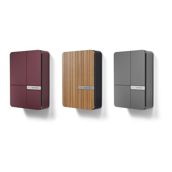
Andersen A2 Installation Manual
Hide thumbs
Also See for A2:
- Installation manual ,
- Installer manual (28 pages) ,
- Quick start manual (24 pages)
Summary of Contents for Andersen A2
- Page 4 30 meters. This can be purchased from Andersen EV. This CT clamp is specifically calibrated for use with the A2 unit. No other CT clamp model is supported for the adaptive fuse feature Please ensure the CT Clamp is installed the correct way round i.e. not recording negative kW.
- Page 5 Arrow on CT clamp should face away from meter and towards all loads i.e. fuse board. Wiring- White to terminal 3 and black to terminal 4. Confirm configuration using the 1 2 3 4 5 CT Test in the installer toolbox. 1 2 3 4 5...
- Page 6 Test Procedure-- Using the CT test in the installer toolbox, compare the value shown to a clamp meter on the supply. Should you suspect solar surplus, turn off the solar supply and compare again. The CT test should now show Configuration appears correct.


Need help?
Do you have a question about the A2 and is the answer not in the manual?
Questions and answers