GORMAN-RUPP PUMPS PA Series Installation, Operation And Maintenance Manual
Hide thumbs
Also See for PA Series:

Subscribe to Our Youtube Channel
Related Manuals for GORMAN-RUPP PUMPS PA Series


Summary of Contents for GORMAN-RUPP PUMPS PA Series
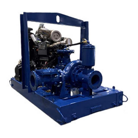
- Page 1 OM-07466-01 October 27, 2021 INSTALLATION, OPERATION, AND MAINTENANCE MANUAL WITH PARTS LIST PA SERIESr PUMP MODEL PA8E60D-4045H FT4-ESP GORMAN‐RUPP PUMPS www.grpumps.com 2021 Gorman‐Rupp Pumps Printed in U.S.A.
- Page 2 Register your new Gorman‐Rupp pump online at www.grpumps.com Valid serial number and e‐mail address required. The engine exhaust from this product contains chemicals known to the State of California to cause cancer, birth defects or other reproductive harm. RECORD YOUR PUMP MODEL AND SERIAL NUMBER Please record your pump model and serial number in the spaces provided below.
-
Page 3: Table Of Contents
TABLE OF CONTENTS INTRODUCTION ..........PAGE I - 1 SAFETY ‐... - Page 4 TABLE OF CONTENTS (continued) Engine Fuel Filter ............PAGE C - 4 Engine Oil .
-
Page 5: Introduction
PA SERIES OM-07466 INTRODUCTION Thank You for purchasing a Gorman‐Rupp pump. HAZARD AND INSTRUCTION Read this manual carefully to learn how to safely DEFINITIONS install and operate your pump. Failure to do so could result in personal injury or damage to the The following are used to alert maintenance per... -
Page 6: Safety - Section A
PA SERIES OM-07466 SAFETY ‐ SECTION A This information applies to Prime Aire the positive battery cable before per Series pumps. Refer to the manual ac forming any maintenance. Failure to do companying the engine or power so may result in serious personal injury. - Page 7 OM-07466 PA SERIES After the pump has been installed, make Make sure the pump is level. Lower jack certain that the pump and all piping or stands and chock the wheels, if so hose connections are tight, properly equipped. Use caution when positioning supported and secure before operation.
-
Page 8: Installation - Section B
PA SERIES OM-07466 INSTALLATION - SECTION B Review all SAFETY information in Section A. configuration, and priming must be tailored to the specific application. Since the pressure supplied Since pump installations are seldom identical, this to the pump is critical to performance and safety,... -
Page 9: Battery Installation
OM-07466 PA SERIES c. Carefully read all tags, decals, and markings POSITIONING PUMP on the pump assembly, and perform all duties indicated. Note that the pump shaft rotates in the required direction. Lifting Only operate this pump in the direction in... -
Page 10: Suction And Discharge Piping
PA SERIES OM-07466 to secure them when filled with liquid and under pressure. Gauges If the pump has been mounted on a mov able base, do not attempt to operate the The pump is drilled and tapped for installing dis... -
Page 11: Sealing
OM-07466 PA SERIES Sealing air to escape from the liquid before it is drawn into the suction inlet. Since even a slight leak will affect priming, head, If two suction lines are installed in a single sump, and capacity, especially when operating with a... -
Page 12: Discharge Lines
PA SERIES OM-07466 Figure 2. Recommended Minimum Suction Line Submergence vs. Velocity DISCHARGE LINES Siphoning If the application involves a high discharge head, gradually close the discharge Do not terminate the discharge line at a level lower than that of the liquid being pumped unless a si... -
Page 13: Float Switch Installation
OM-07466 PA SERIES Float Switch Installation pipe is available, attach the float switch cable to the standpipe in the sump at the approxi mate desired liquid level. The Float Switch autostart system employs either a single or double float switch, where a bulb raises or lowers (floats) with the liquid level, thus activating b. - Page 14 PA SERIES OM-07466 that the liquid in the priming chamber never fully Next, install a drain line between the pump drain freezes. and the wet well or sump. This line must remain submerged in the liquid below the pump down lev...
-
Page 15: Operation - Section C
OM-07466 PA SERIES OPERATION - SECTION C OPERATION Review all SAFETY information in Section A. Make sure the pump is level. Lower jack Follow the instructions on all tags, labels and stands and chock the wheels, if so decals attached to the pump. -
Page 16: Routine Operation
OM-07466 PA SERIES down the pump and consult Maintenance and OPERATIONAL CHECKS Repair, Section E for further details. ROUTINE OPERATION The engine powering this unit may be equipped with an EPA‐compliant Exhaust After‐Treatment (EAT) system, which is de signed to reduce the amount of polutants Do not operate an internal combustion expelled into the atmosphere during oper... -
Page 17: Strainer Check
OM-07466 PA SERIES restart automatically when the liquid rises and acti pletely cool before servicing. Do not re vates the “On” liquid level device(s). move plates, covers, gauges, or fittings from an overheated pump. Liquid within the pump can reach boiling tempera... - Page 18 OM-07466 PA SERIES normal for bearings, and they can operate safely to Consult the manual accompanying the engine, at least 180 F (82 and change the oil filter periodically as indicated. If operated under extremely dusty conditions, Checking bearing temperatures by hand is inaccu...
- Page 19 OM-07466 PA SERIES TROUBLESHOOTING - SECTION D Review all SAFETY information in Section A. 5. Close the suction and discharge valves. 6. Vent the pump slowly and cau tiously. 7. Drain the pump. Before attempting to open or service the pump: 1.
- Page 20 OM-07466 PA SERIES TROUBLE POSSIBLE CAUSE PROBABLE REMEDY Check strainer and clean if neces Strainer clogged. PUMP STOPS OR FAILS TO DELIVER sary. RATED FLOW OR Check and clean check valve. Discharge check valve clogged. PRESSURE (cont.) Suction intake not submerged at Check installation and correct proper level or sump too small.
- Page 21 OM-07466 PA SERIES TROUBLE POSSIBLE CAUSE PROBABLE REMEDY BEARINGS RUN Bearing temperature is high, but Check bearing temperature regu TOO HOT within limits. larly to monitor any increase. Low or incorrect lubricant. Check for proper type and level of lubricant.
- Page 22 OM-07466 PA SERIES Preventive Maintenance Schedule Service Interval* Item Daily Weekly Monthly Semi‐ Annually Annually General Condition (Temperature, Unusual Noises or Vibrations, Cracks, Leaks, Loose Hardware, Etc.) Pump Performance (Gauges, Speed, Flow) Bearing Lubrication Seal Lubrication (And Packing Adjustment, If So Equipped) V‐Belts (If So Equipped)
- Page 23 OM-07466 PA SERIES PUMP MAINTENANCE AND REPAIR - SECTION E MAINTENANCE AND REPAIR OF THE WEARING PARTS OF THE PUMP WILL MAINTAIN PEAK OPERATING PERFORMANCE. STANDARD PERFORMANCE FOR PUMP MODEL PA8E60D-4045H FT4-ESP Based on 70 F (21 C) clear water at sea level Contact the Gorman‐Rupp Company to verify per...
- Page 24 OM-07466 PA SERIES PARTS PAGE ILLUSTRATION 11 12 Figure 1. Pump Model PA8E60D-4045H FT4-ESP PAGE E - 2 MAINTENANCE & REPAIR...
- Page 25 OM-07466 PA SERIES Pump Model PA8E60D-4045H FT4-ESP PARTS LIST (From S/N 1767886 Up) ITEM PART PART NAME NUMBER PUMP END ASSEMBLY 46183-246 POWER UNIT J DEERE 4045H FT4 46143-247 ENCLOSURE ASSEMBLY 42164-056 T-BOLT CLAMP 4-1/2" 26518-166 AIR INTAKE PIPE 31418-163 15210 90 DEG COBRA ELBOW, 4"...
- Page 26 OM-07466 PA SERIES ILLUSTRATION DETAIL A 10 40 10 40 Ñ Ñ Ï Ï Ï Ñ 4 5 6 15 16 17 Figure 2. Power Unit Kit PAGE E - 4 MAINTENANCE & REPAIR...
- Page 27 OM-07466 PA SERIES PARTS LIST Power Unit Kit ITEM PART NAME PART ITEM PART NAME PART NUMBER NUMBER BASE/FUEL TANK ASSY 41553-064 24150 .37 ID X 60" LG HOSE 18513-302 LIFTING BAIL KIT 48274-817 HOSE BARB FITTING 26523-447 JD 4045H FT4 ENGINE...
- Page 28 OM-07466 PA SERIES ILLUSTRATION 29 30 Figure 3. Pump End Assembly PAGE E - 6 MAINTENANCE & REPAIR...
- Page 29 OM-07466 PA SERIES Pump End Assembly PARTS LIST ITEM PART NAME PART ITEM PART NAME PART NUMBER NUMBER PUMP CASING SEE NOTE BELOW T-BOLT CLAMP 1.5 IN 26518-181 STUD C1211 15991 1" ID X 24" LG HOSE 18513-321 WEAR RING...
- Page 30 OM-07466 PA SERIES ILLUSTRATION Ç Ç Ç Ç Ç Ç Ç Ç Ç Ç Ç Ç Ç Ç Ç Ñ Ñ Ñ Ñ Ñ Ñ Ñ Ñ Ç Ç Ç Ç Ç Ç Ç Ç Ñ Ñ Ñ Ñ Ñ Ñ...
- Page 31 OM-07466 PA SERIES PARTS LIST Repair Rotating Assembly ITEM PART PART NAME NUMBER IMPELLER 38621-799 11010 SOCKET HEAD CAP SCREW DM1206 15991 WASHER NORD-LOCK 3/4" 21177-224 IMPELLER WASHER 31167-042 17000 ROLL PIN S2197 SHIM SET 48261-033 3.25" MECH SEAL 25285-822...
- Page 32 OM-07466 PA SERIES ILLUSTRATION Figure 5. Priming Chamber Kit ITEM PART PART NAME NUMBER BALL VALVE 26631-054 STREET ELBOW RS16 11999 PRIMING CHAMBER ASSY 46112-709 HEX NUT D08 15991 LOCK WASHER J08 15991 STUD C0809 15991 BAFFLE 31113-011 17000 GASKET...
- Page 33 OM-07466 PA SERIES ILLUSTRATION Figure 6. Priming Chamber Assembly PARTS LIST ITEM PART PART NAME NUMBER PRIMING VALVE 26664-007 -ORIFICE BUTTON 26688-021 HEX HD CAPSCREW B0806 15991 LOCKWASHER J08 15991 PRIMING VALVE GASKET 38683-657 19060 PRIMING CHAMBER 38343-020 10000 STRAINER ASSY...
- Page 34 OM-07466 PA SERIES ILLUSTRATION Figure 7. Drive Assembly ITEM PART PART NAME NUMBER COUPLING KIT 48112-006 -BUSHING 24131-492 -COUPLING ASSEMBLY 24391-106 -LOCK WASHER 21171-536 -HEX HD CAPSCREW B0612 15991 -HEX HD CAPSCREW 22645-174 HEX HEAD CAPSCREW BD0606 15991 HEX HEAD CAPSCREW...
- Page 35 OM-07466 PA SERIES PUMP AND SEAL DISASSEMBLY 3. Allow the pump to completely cool if overheated. AND REASSEMBLY 4. Check the temperature and make sure it is cool before opening any Review all SAFETY information in Section A. covers, plates, gauges, or plugs.
- Page 36 OM-07466 PA SERIES If the priming valve float is stuck or the strainer (6) is good working condition and of suffi clogged, it can usually be cleaned without further cient capacity and that they are posi disassembly. tioned so that loads will be balanced...
- Page 37 OM-07466 PA SERIES Remove and discard the O‐ring (4). Separating Pump and Drive Assembly From Engine Inspect the wear ring and, if replacement is re (Figure 7) quired, install two 1/2-13 UNC‐2B capscrews (not supplied) in the tapped holes in the suction head...
- Page 38 OM-07466 PA SERIES impeller (1) and the pump casing (1, Figure 3) to hardware (5 and 6) and pull the wear ring out of the prevent rotation. pump casing. Install the shaft key (26) in the shaft keyway. Install Impeller Removal a lathe dog on the drive end of the shaft (25) with the “V”...
- Page 39 OM-07466 PA SERIES sparks, and flame. Read and follow all precautions printed on solvent contain ers. Clean the bearings thoroughly in fresh cleaning Shaft and bearing disassembly in the field solvent. Dry the bearings with filtered compressed is not recommended. These operations air and coat with light oil.
- Page 40 OM-07466 PA SERIES The bearings may be heated to ease installation. An induction heater, hot oil bath, electric oven, or hot plate may be used to heat the bearings. Bear ings should never be heated with a direct flame or It is recommended that a new bearing lock directly on a hot plate.
- Page 41 OM-07466 PA SERIES just flush with the machined surface on the hous condition can cause premature bearing ing. failure. The end of the shaft must extend 0.44 Apply a light coating of oil to the lip of the oil seal inch (11mm) from the face of the bush...
- Page 42 OM-07466 PA SERIES seat bore in the seal plate for dirt, nicks and burrs, pump. Wear patterns on the finished faces and remove any that exist. The stationary seat bore cannot be realigned during reassembly. must be completely clean before installing the Reusing an old seal could result in prema...
- Page 43 OM-07466 PA SERIES sleeve until the rotating element is just flush with Suction Head and Wear Ring Installation the chamfered end of the sleeve. Slide the shaft (Figure 3) sleeve and rotating subassembly onto the shaft If the wear ring (3) was removed, position the re...
- Page 44 OM-07466 PA SERIES Priming Chamber Assembly and Installation (Figure 6) Clean and inspect the components of the priming valve (1). Inspect the linkage and ensure the orifice button (not shown) squarely engages the valve seat. Replace the orifice button if required (see Priming Chamber Removal and Disassembly for orifice button removal).
- Page 45 OM-07466 PA SERIES little oil on it. Clean and reinstall the air vent. Check When lubricating a new bearing pedestal, pack the the oil level regularly through the sight gauge (22) bearings by hand with lithium EP2 grease until fully and maintain it at the midpoint of the gauge.
- Page 46 For Warranty Information, Please Visit www.grpumps.com/warranty or call: U.S.: 419-755-1280 Canada: 519-631-2870 International: +1-419-755-1352 GORMAN‐RUPP PUMPS...
Need help?
Do you have a question about the PA Series and is the answer not in the manual?
Questions and answers