
Related Manuals for Oshkosh Corporation JLG 740AJ


Summary of Contents for Oshkosh Corporation JLG 740AJ
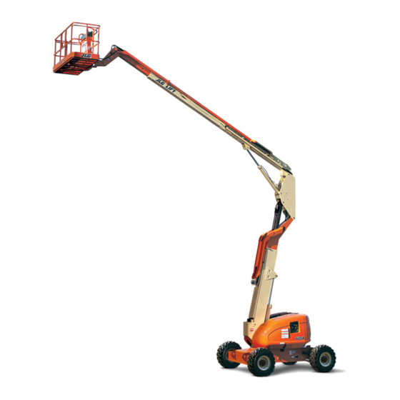
- Page 1 Operation and Safety Manual Original Instructions - Keep this manual with the machine at all times. Boom Lift Models 740AJ prior to S/N 0300185827 ANSI 3121159 March 31, 2014 ®...
- Page 2 TO PURCHASE THIS PRODUCT PLEASE CONTACT US Equipment Financing and Extended Warranties Available Discount-Equipment.com is your online resource for commercial and industrial quality parts and equipment sales. 561-964-4949 visit us on line @ www.discount-equipment.com Select an option below to find your Equipment We sell worldwide for the brands: Genie, Terex, JLG, MultiQuip, Mikasa, Essick, Whiteman, Mayco, Toro Stone, Diamond Products, Generac Magnum, Airman, Haulotte, Barreto, Power Blanket, Nifty Lift, Atlas Copco, Chicago Pneumatic, Allmand, Miller Curber, Skyjack, Lull,...
- Page 3 FOREWORD FOREWORD This manual is a very important tool! Keep it with the machine at all times. The purpose of this manual is to provide owners, users, operators, lessors, and lessees with the precautions and operating procedures essential for the safe and proper machine operation for its intended purpose. Due to continuous product improvements, JLG Industries, Inc.
- Page 4 FOREWORD SAFETY ALERT SYMBOLS AND SAFETY SIGNAL WORDS This is the Safety Alert Symbol. It is used to alert you to the potential personal injury hazards. Obey all safety messages that follow this symbol to avoid possible injury or death INDICATES A POTENTIALLY HAZARDOUS SITUATION.
- Page 5 FOREWORD For: THIS PRODUCT MUST COMPLY WITH ALL SAFETY RELATED BULLE- • Accident Reporting • Standards and Regulations TINS. CONTACT JLG INDUSTRIES, INC. OR THE LOCAL AUTHORIZED Compliance Information • Product Safety Publica- JLG REPRESENTATIVE FOR INFORMATION REGARDING SAFETY- tions •...
- Page 6 FOREWORD REVISION LOG Original Issue - November 4, 2002 Revised - April 1, 2003 Revised - July 7, 2005 Revised - March 8, 2006 Revised - July 20, 2006 Revised - January 15, 2007 Revised - September 28, 2007 Revised - December 9, 2009 Revised - May 23, 2012...
-
Page 7: Table Of Contents
TABLE OF CONTENTS SECTION - PARAGRAPH, SUBJECT PAGE SECTION - PARAGRAPH, SUBJECT PAGE SECTION - 1 - SAFETY PRECAUTIONS FUNCTION CHECK......2-10 From the Ground Control Station with No Load in the GENERAL . - Page 8 TABLE OF CONTENTS SECTION - PARAGRAPH, SUBJECT PAGE SECTION - PARAGRAPH, SUBJECT PAGE ENGINE OPERATION ..... . . 4-2 Changing From Gasoline to LP Gas ..4-19 Starting Procedure .
- Page 9 TABLE OF CONTENTS SECTION - PARAGRAPH, SUBJECT PAGE SECTION - PARAGRAPH, SUBJECT PAGE Hydraulic Oil ......6-6 2-6.
- Page 10 TABLE OF CONTENTS SECTION - PARAGRAPH, SUBJECT PAGE SECTION - PARAGRAPH, SUBJECT PAGE - Sheet 1 of 2 ......6-10 LIST OF TABLES 6-2.
-
Page 11: Section 1. Safety Precautions
SECTION 1 - SAFETY PRECAUTIONS SECTION 1. SAFETY PRECAUTIONS GENERAL PRE-OPERATION This section outlines the necessary precautions for proper Operator Training and Knowledge and safe machine operation and maintenance. For proper machine use, it is mandatory that a daily routine is estab- •... -
Page 12: Workplace Inspection
SECTION 1 - SAFETY PRECAUTIONS Machine Inspection • Read, understand, and obey all DANGERS, WARNINGS, CAUTIONS, and operating instructions on the machine • Before machine operation, perform inspections and func- and in this manual. tional checks. Refer to Section 2 of this manual for •... -
Page 13: Operation
SECTION 1 - SAFETY PRECAUTIONS OPERATION • Supplies or tools which extend outside the platform are prohibited unless approved by JLG. General • When driving, always position boom over rear axle in line with the direction of travel. Remember, if boom is over the •... -
Page 14: Electrocution Hazards
SECTION 1 - SAFETY PRECAUTIONS • Before operating the machine, make sure all gates are • Use extreme caution when entering or leaving platform. closed and fastened in their proper position. Be sure that the boom is fully lowered. It may be neces- sary to telescope out to position the platform closer to the ground for entry/exit. -
Page 15: Minimum Approach Distances (M.a.d.)
SECTION 1 - SAFETY PRECAUTIONS Table 1-1. Minimum Approach Distances (M.A.D.) Voltage Range MINIMUM APPROACH DISTANCE (Phase to Phase) in Feet (Meters) 0 to 50 KV 10 (3) Over 50KV to 200 KV 15 (5) Over 200 KV to 350 KV 20 (6) Over 350 KV to 500 KV 25 (8) -
Page 16: Tipping Hazards
SECTION 1 - SAFETY PRECAUTIONS Tipping Hazards • The minimum approach distance may be reduced if insulat- ing barriers are installed to prevent contact, and the barriers • The user should be familiar with the surface before driv- are rated for the voltage of the line being guarded. These ing. -
Page 17: Crushing And Collision Hazards
SECTION 1 - SAFETY PRECAUTIONS • Do not elevate platform or drive with platform elevated • If boom assembly or platform is in a position that one or while on a sloping, uneven, or soft surface. more wheels are off the ground, all persons must be removed before attempting to stabilize the machine. -
Page 18: Towing, Lifting, And Hauling
SECTION 1 - SAFETY PRECAUTIONS TOWING, LIFTING, AND HAULING • Use the boom functions, not the drive function, to position the platform close to obstacles. • Never allow personnel in platform while towing, lifting, or • Always post a lookout when driving in areas where vision hauling. -
Page 19: Additional Hazards / Safety
SECTION 1 - SAFETY PRECAUTIONS ADDITIONAL HAZARDS / SAFETY • Do not refuel the machine with the engine running. • Battery fluid is highly corrosive. Avoid contact with skin • Do not use machine as a ground for welding. and clothing at all times. •... -
Page 20: Beaufort Scale (For Reference Only)
SECTION 1 - SAFETY PRECAUTIONS DO NOT OPERATE THE MACHINE WHEN WIND CONDITIONS EXCEED 28 MPH (12.5 M/S). Table 1-2. Beaufort Scale (For Reference Only) Wind Speed Beaufort Description Land Conditions Number 0-0.2 Calm Calm. Smoke rises vertically. 0.3-1.5 Light air Wind motion visible in smoke. -
Page 21: Section 2. User Responsibilities, Machine Preparation, And Inspection
SECTION 2 - USER RESPONSIBILITIES, MACHINE PREPARATION, AND INSPECTION SECTION 2. USER RESPONSIBILITIES, MACHINE PREPARATION, AND INSPECTION 2.1 PERSONNEL TRAINING 6. The safest means to operate the machine where over- head obstructions, other moving equipment, and obsta- The aerial platform is a personnel handling device; so it is cles, depressions, holes, drop-offs. -
Page 22: Preparation, Inspection, And Maintenance
SECTION 2 - USER RESPONSIBILITIES, MACHINE PREPARATION, AND INSPECTION PREPARATION, INSPECTION, AND MAINTENANCE JLG INDUSTRIES, INC. RECOGNIZES A FACTORY-QUALIFIED SERVICE TECHNICIAN AS A PERSON WHO HAS SUCCESSFULLY COMPLETED The following table covers the periodic machine inspections THE JLG SERVICE TRAINING SCHOOL FOR THE SPECIFIC JLG PRODUCT and maintenance required by JLG Industries, Inc. -
Page 23: Inspection And Maintenance Table
SECTION 2 - USER RESPONSIBILITIES, MACHINE PREPARATION, AND INSPECTION Table 2-1. Inspection and Maintenance Table Primary Service Type Frequency Reference Responsibility Qualification Pre-Start Inspection Before using each day; or User or Operator User or Operator Operator and Safety Manual whenever there’s an Operator change. Pre-Delivery Inspection (See Before each sale, lease, or rental delivery. -
Page 24: Pre-Start Inspection
SECTION 2 - USER RESPONSIBILITIES, MACHINE PREPARATION, AND INSPECTION Pre-Start Inspection (Domestic only) is enclosed in the weather resistant storage container. The Pre-Start Inspection should include each of the follow- 5. “Walk-Around” Inspection – Refer to Figure 2-2. thru ing: Figure 2-5. - Page 25 SECTION 2 - USER RESPONSIBILITIES, MACHINE PREPARATION, AND INSPECTION 3121159 – JLG Lift –...
-
Page 26: Daily Walk-Around Inspection. (Sheet 1 Of 4)
SECTION 2 - USER RESPONSIBILITIES, MACHINE PREPARATION, AND INSPECTION 2,22,23,24,25,26 14,15,16,17,18,19,20 9,10 3,4,5 38,39 9,10 26,31,32,33,34 35,36 Figure 2-2. Daily Walk-Around Inspection. (Sheet 1 of 4) – JLG Lift – 3121159... -
Page 27: General
SECTION 2 - USER RESPONSIBILITIES, MACHINE PREPARATION, AND INSPECTION GENERAL 3. Rotator - See Inspection Note. 4. Rotator Motion Control Valve - See Inspection Note. Begin the "Walk-Around Inspection" at Item 1, as noted on the diagram. Continue to the right (counterclockwise 5. -
Page 28: Daily Walk-Around Inspection. (Sheet 3 Of 4)
SECTION 2 - USER RESPONSIBILITIES, MACHINE PREPARATION, AND INSPECTION 14. Turntable Lock - See Inspection Note. 23. Hydraulic Oil Breather - Element in place, not clogged, no sign of overflow. 15. Auxiliary Power Pump - See Inspection Note. 24. Fuel Supply - Fuel filler cap secure. Tank - See 16. -
Page 29: Daily Walk-Around Inspection. (Sheet 4 Of 4)
SECTION 2 - USER RESPONSIBILITIES, MACHINE PREPARATION, AND INSPECTION 31. Engine Air Filter - No loose or missing parts; no visi- 40. Tower Boom - No visible damage; wear pads secure. ble damage; element clean. All cylinders - rod end shafts and barrel-end shafts properly secured. -
Page 30: Function Check
SECTION 2 - USER RESPONSIBILITIES, MACHINE PREPARATION, AND INSPECTION FUNCTION CHECK horizontal position. While raising and lowering the tower boom assembly, observe the position of the upright. Perform a function check of all systems, once the walk- Ensure that the upright remains vertical relative to the around inspection is complete, in an area free of overhead chassis. - Page 31 SECTION 2 - USER RESPONSIBILITIES, MACHINE PREPARATION, AND INSPECTION 3121159 – JLG Lift – 2-11...
- Page 32 SECTION 2 - USER RESPONSIBILITIES, MACHINE PREPARATION, AND INSPECTION 2-12 – JLG Lift – 3121159...
-
Page 33: From The Platform Control Station
SECTION 2 - USER RESPONSIBILITIES, MACHINE PREPARATION, AND INSPECTION From the Platform Control Station: c. Check adjustment of footswitch. Footswitch must be adjusted so that functions will operate when 1. Check that the control console is secure and all guards pedal is approximately at its center of travel. - Page 34 SECTION 2 - USER RESPONSIBILITIES, MACHINE PREPARATION, AND INSPECTION c. With main boom in this position, raise the main 9. Check the high-engine cutout for the main boom assem- base boom until the capacity indicator lights bly as follows: change back to the 1000 lb. (454 kg) indicator. a.
- Page 35 SECTION 2 - USER RESPONSIBILITIES, MACHINE PREPARATION, AND INSPECTION 11. Check the Tilt Alarm and Warning System as follows: 13. Check that the platform level override operates properly. 14. Check platform rotator for smooth operation and assure platform will rotate 90 degrees in both directions from IF THE TILT ALARM AND WARNING SYSTEM DOES NOT OPERATE centerline of boom.
-
Page 36: Oscillating Axle Lockout Test (If Equipped)
SECTION 2 - USER RESPONSIBILITIES, MACHINE PREPARATION, AND INSPECTION OSCILLATING AXLE LOCKOUT TEST (IF 6. With boom over right side of machine, place DRIVE con- trol lever to REVERSE and drive machine off of block EQUIPPED) and ramp. 7. Have an assistant check to see that left front or right rear wheel remains elevated in position off of ground. -
Page 37: Inspection And Use Of Fall Arrest System
SECTION 2 - USER RESPONSIBILITIES, MACHINE PREPARATION, AND INSPECTION 14. Carefully activate SWING control lever and return boom to stowed position (centered between drive wheels). When boom reaches center, stowed position, lockout DO NOT OPERATE ANY MACHINE FUNCTIONS WHILE OUTSIDE OF cylinders should release and allow wheel to rest on PLATFORM. -
Page 38: Prior To Use Inspection
SECTION 2 - USER RESPONSIBILITIES, MACHINE PREPARATION, AND INSPECTION Inspecting Cable Tension and Slip Indicator IF THE FALL ARREST SYSTEM IS USED TO ARREST A FALL OR IS OTH- Cable tension is adjusted by using the Line Tenser. The Line ERWISE DAMAGED, THE ENTIRE SYSTEM MUST BE REPLACED AND Tenser is the disc at the end of the cable (shown below). - Page 39 SECTION 2 - USER RESPONSIBILITIES, MACHINE PREPARATION, AND INSPECTION The slip indicator is the short tube crimped beside the end connection of the cable. If the cable slips from the end con- nection a gap will be present between the slip indicator and the end connection.
-
Page 40: Fall Arrest System
SECTION 2 - USER RESPONSIBILITIES, MACHINE PREPARATION, AND INSPECTION Transfastener Bracket Cable Swage/Slip Indicator Turnbuckle Line Tenser Figure 2-8. Fall Arrest System 2-20 – JLG Lift – 3121159... - Page 41 TO PURCHASE THIS PRODUCT PLEASE CONTACT US Equipment Financing and Extended Warranties Available Discount-Equipment.com is your online resource for commercial and industrial quality parts and equipment sales. 561-964-4949 visit us on line @ www.discount-equipment.com Select an option below to find your Equipment We sell worldwide for the brands: Genie, Terex, JLG, MultiQuip, Mikasa, Essick, Whiteman, Mayco, Toro Stone, Diamond Products, Generac Magnum, Airman, Haulotte, Barreto, Power Blanket, Nifty Lift, Atlas Copco, Chicago Pneumatic, Allmand, Miller Curber, Skyjack, Lull,...
-
Page 42: Section 3. Machine Controls And Indicators
SECTION 3 - MACHINE CONTROLS AND INDICATORS SECTION 3. MACHINE CONTROLS AND INDICATORS GENERAL Ground Control Station NOTE: Main Lift, Swing, Platform Level, Main Telescope, Platform Rotator and Auxiliary Power, Tower Lift, and jib control THE MANUFACTURER HAS NO DIRECT CONTROL OVER MACHINE switches are spring-loaded and will automatically return APPLICATION AND OPERATION. -
Page 43: Ground Control Station
SECTION 3 - MACHINE CONTROLS AND INDICATORS 1. Platform Rotate 2. Platform Leveling Override 3. Jib 4. Power/Emergency Stop 5. Engine Start/Auxiliary Power Engine Start/Auxiliary Power/Function Enable 6. Hourmeter 7. Platform/Ground Select Switch 8. Swing 9. Tower Lift 10. Main Boom Lift 11. - Page 44 SECTION 3 - MACHINE CONTROLS AND INDICATORS NOTE: When Power/Emergency Stop switch is in the “ON” posi- tion and engine is not running, an alarm will sound, indi- ONLY USE THE PLATFORM LEVELING OVERRIDE FUNCTION FOR cating Ignition is “ON”. SLIGHT LEVELING OF THE PLATFORM.
- Page 45 SECTION 3 - MACHINE CONTROLS AND INDICATORS 5. Engine Start/Auxiliary Power Switch 6. Hourmeter Engine Start/ Auxiliary Power Switch /Function Enable. An hour meter, installed in the bottom portion of the Ground Control box, registers the amount of time the To start the engine, the switch must be held "UP"...
- Page 46 SECTION 3 - MACHINE CONTROLS AND INDICATORS 8. Swing Control The SWING control switch provides 360 degrees contin- TO AVOID SERIOUS INJURY, DO NOT OPERATE MACHINE IF ANY CON- uous turntable rotation when positioned to RIGHT or TROL LEVERS OR TOGGLE SWITCHES CONTROLLING PLATFORM LEFT.
-
Page 47: Ground Control Indicator Panel
SECTION 3 - MACHINE CONTROLS AND INDICATORS Ground Control Indicator Panel 1. Battery Discharging Indicator When illuminated indicates a problem in the battery or charging circuit, and service is required. 2. Engine Oil Pressure Indicator When illuminated indicates that engine oil pressure is below normal and service is required. - Page 48 SECTION 3 - MACHINE CONTROLS AND INDICATORS 5. Engine Malfunction Indicator Light (Ford Engines prior 8. Boom Malfunction Indicator to S/N 62045) If the Boom Malfunction Indicator illuminates when Indicates that the Engine Control Module has detected a attempting to activate a tower boom function, the func- malfunction in the Electronic Fuel Injection System and tion is being cutout by tower boom limit switch.
-
Page 49: Platform Station
SECTION 3 - MACHINE CONTROLS AND INDICATORS Platform Station 9. Platform Overload (If equipped) Indicates the platform has been overloaded. 1. Power/Emergency Stop 10. Hydraulic Oil Filter Indicator (Prior to S/N 85331) An ON-OFF POWER/EMERGENCY STOP switch and a separate ENGINE START/AUXILIARY POWER toggle A gauge indicates that the return oil filter is too restrictive switch on the platform console supply electrical power and needs to be replaced. - Page 50 SECTION 3 - MACHINE CONTROLS AND INDICATORS 4. Main Telescope Control NOTE: When main boom is positioned above horizontal and any of the following switches, DRIVE SPEED/TORQUE The MAIN TELESCOPE control switch provides exten- SELECT or FUNCTION SPEED, are positioned to HIGH, sion and retraction of the main boom when positioned to high function speeds are automatically set to creep and IN or OUT.
-
Page 51: Platform Control Console
SECTION 3 - MACHINE CONTROLS AND INDICATORS 1702676-B 1704997 1702567 A 1. Power/Emergency Stop 5. Drive/Steer 9. Platform Level Override 13. Steer Select 2. Horn 6. Function Speed Control 10. Articulating Jib 14. Engine Start / Aux Power 3. Main Lift / Swing 7. -
Page 52: Platform Control Console - W/Drive Orientation
SECTION 3 - MACHINE CONTROLS AND INDICATORS 1702676-B 1704997 1702567 A 1702938 1705170 A 1. Power/Emergency Stop 6. Function Speed Control 11. Fuel Select 16. Drive Orientation Override 2. Horn 7. Drive Speed / Torque Select 12. Lights 17. Soft Touch Override 3. - Page 53 SECTION 3 - MACHINE CONTROLS AND INDICATORS 7. Drive Speed/Torque Select Drive Speed/Torque Select is a three position switch The ONLY USE THE PLATFORM LEVELING OVERRIDE FUNCTION FOR forward position gives maximum drive speed by shifting SLIGHT LEVELING THE PLATFORM. INCORRECT USE COULD the drive motors to minimum the displacement and giv- CAUSE THE LOAD/OCCUPANT TO SHIFT OR FALL.
- Page 54 SECTION 3 - MACHINE CONTROLS AND INDICATORS 12. Work Lights. (If Equipped) To re-synchronize the front and rear axles, activate the The switch, on the light, operates work lights if the steer switch (thumb rocker) until all steer cylinders are at machine is so equipped.
- Page 55 SECTION 3 - MACHINE CONTROLS AND INDICATORS 15. Tower Lift 17. Soft Touch Override Switch (If equipped) The three position center-off toggle switch provides for This switch enables the functions that were cut out by raising and lowering of the tower boom when positioned the Soft Touch system to operate again at creep speed, to “UP”...
-
Page 56: Platform Control Indicator Panel
SECTION 3 - MACHINE CONTROLS AND INDICATORS Platform Control Indicator Panel NOTE: For engine starting, the footswitch must be in the released (up) position. Footswitch must be actuated in order for controls to function. NOTE: The platform control indicator panel uses different shaped symbols to alert the operator to different types of opera- NOTE: These machines have a 7 second delay timer. - Page 57 SECTION 3 - MACHINE CONTROLS AND INDICATORS 1. Footswitch/Enable Indicator 2. Engine Malfunction Indicator To operate any function, the footswitch must be On machines prior to S/N 62045, the light turns on and depressed and the function selected within seven sec- an alarm sounds when machine’s power system onds.
-
Page 58: Platform Light Panel
SECTION 3 - MACHINE CONTROLS AND INDICATORS * UNRESTRICTED CAPACITY ** RESTRICTED CAPACITY 1. Enable 7. Creep Speed 2. Engine Malfunction 8. Glow Plug 3. Soft Touch 9. Tilt Alarm Warning 4. AC Generator 10. Overload 5. Fuel Level 11. Boom Malfunction 6. -
Page 59: Platform Light Panel W/Drive Orientation
SECTION 3 - MACHINE CONTROLS AND INDICATORS 1001107927 A * UNRESTRICTED CAPACITY ** RESTRICTED CAPACITY 1. Enable 5. Fuel Level 9. Tilt Alarm Warning 2. Engine Malfunction 6. Capacity 10. Overload 3. Not Used 7. Creep Speed 11. Boom Malfunction 4. - Page 60 SECTION 3 - MACHINE CONTROLS AND INDICATORS 3. Soft Touch Indicator (If Equipped) 6. Capacity Indicator (If equipped) When illuminated (Yellow) the Soft Touch bumper is Indicates the maximum platform capacity for the current against an object. All controls are disabled until the position of the platform.
- Page 61 SECTION 3 - MACHINE CONTROLS AND INDICATORS 9. Tilt Alarm Warning Light and Alarm 10. Overload Indicator (If equipped) This orange illuminator indicates that the chassis is on a Indicates the platform has been overloaded. slope. An alarm will also sound when the chassis is on a slope and the boom is above horizontal.
- Page 62 SECTION 3 - MACHINE CONTROLS AND INDICATORS 11. Boom Malfunction Indicator 12. Drive Orientation Indicator When an audible alarm sounds and the Boom Malfunc- When the boom is swung beyond the rear drive tires or tion Indicator illuminates when attempting to activate a further in either direction, the Drive Orientation indicator tower boom function, the function is being cutout by will illuminate when the drive function is selected.
- Page 63 SECTION 3 - MACHINE CONTROLS AND INDICATORS NOTES: 3-22 – JLG Lift – 3121159...
- Page 64 TO PURCHASE THIS PRODUCT PLEASE CONTACT US Equipment Financing and Extended Warranties Available Discount-Equipment.com is your online resource for commercial and industrial quality parts and equipment sales. 561-964-4949 visit us on line @ www.discount-equipment.com Select an option below to find your Equipment We sell worldwide for the brands: Genie, Terex, JLG, MultiQuip, Mikasa, Essick, Whiteman, Mayco, Toro Stone, Diamond Products, Generac Magnum, Airman, Haulotte, Barreto, Power Blanket, Nifty Lift, Atlas Copco, Chicago Pneumatic, Allmand, Miller Curber, Skyjack, Lull,...
-
Page 65: Section 4. Machine Operation
SECTION 4 - MACHINE OPERATION SECTION 4. MACHINE OPERATION DESCRIPTION OPERATING CHARACTERISTICS AND LIMITATIONS This machine is a self-propelled hydraulic lift equipped with a work platform on the end of an elevating and rotating boom. Capacities The primary operator control station is in the platform. From The boom can be raised above horizontal with or without any this control station, the operator can drive and steer the load in the platform if:... -
Page 66: Engine Operation
SECTION 4 - MACHINE OPERATION MACHINES WITH DIESEL ENGINES. AFTER TURNING ON IGNITION, OPERATOR MUST WAIT UNTIL GLOW PLUG INDICATOR LIGHT GOES TO AVOID FORWARD OR BACKWARD TIPPING, DO NOT OVERLOAD OUT BEFORE CRANKING ENGINE.(IF EQUIPPED) MACHINE OR OPERATE ON AN OUT-OF-LEVEL SURFACE. 4. - Page 67 SECTION 4 - MACHINE OPERATION Figure 4-1. Position of Least Forward Stability 3121159 – JLG Lift –...
-
Page 68: Positions Of Least Backward Stability
SECTION 4 - MACHINE OPERATION Figure 4-2. Positions of Least Backward Stability (Sheet 1 of 2) – JLG Lift – 3121159... -
Page 69: Positions Of Least Backward Stability
SECTION 4 - MACHINE OPERATION Figure 4-3. Positions of Least Backward Stability (Sheet 2 of 2) 3121159 – JLG Lift –... -
Page 70: Shutdown Procedure
SECTION 4 - MACHINE OPERATION Shutdown Procedure TO AVOID LOSS OF TRAVEL CONTROL OR “TIP OVER” , DO NOT DRIVE MACHINE ON GRADES EXCEEDING THOSE SPECIFIED ON THE SERIAL NUMBER PLATE. DO NOT DRIVE ON SIDESLOPES WHICH EXCEED 5 DEGREES (ANSI) OR IF AN ENGINE MALFUNCTION NECESSITATES UNSCHEDULED SHUT- 3 DEGREES (CE/AUS). -
Page 71: Traveling Forward And Reverse
SECTION 4 - MACHINE OPERATION Traveling Forward and Reverse PARKING AND STOWING Park and stow machine as follows: 1. At Platform Controls, pull out Emergency Stop switch, start engine, and activate footswitch. 1. Park machine in travel position; boom lowered over rear, all access panels and doors closed and secured, igni- 2. -
Page 72: Platform
SECTION 4 - MACHINE OPERATION PLATFORM Platform Level Adjustment Loading From Ground Level 1. Leveling UP . Depress footswitch To raise platform, posi- tion PLATFORM LEVEL control switch UP and hold until platform is level. 1. Position chassis on a smooth, firm and level surface. 2. - Page 73 SECTION 4 - MACHINE OPERATION LEVEL Figure 4-4. Grade and Sideslopes. 3121159 – JLG Lift –...
-
Page 74: Boom
SECTION 4 - MACHINE OPERATION BOOM TRAVELING WITH MAIN BOOM RETRACTED AND BELOW HORIZONTAL IS PERMITTED ON GRADES AND SIDE SLOPES SPECIFIED ON THE (See Figure 4-4.) SERIAL NUMBER PLACARD. TO AVOID SERIOUS INJURY, DO NOT OPERATE MACHINERY IF ANY CONTROL LEVERS OR TOGGLE SWITCHES CONTROLLING PLATFORM AN ORANGE TILT ALARM WARNING LIGHT, LOCATED ON THE CONTROL MOVEMENT DO NOT RETURN TO THE OFF OR NEUTRAL POSITION... -
Page 75: Raising And Lowering The Tower Boom
SECTION 4 - MACHINE OPERATION Raising and Lowering the Tower Boom Telescoping the Main Boom To raise or lower the Tower Boom, depress footswitch, posi- To extend or retract Main Boom, depress footswitch, position tion TOWER LIFT controller UP OR DOWN, and hold until the MAIN TELESCOPE control switch to IN or OUT, and hold desired height is reached until platform reaches desired position. -
Page 76: 4.10 Lifting And Tie Down
SECTION 4 - MACHINE OPERATION 4.10 LIFTING AND TIE DOWN NOTE: Crane and lifting devices, chains, slings, etc., must be capable of handling the gross machine weight. When transporting machine, boom must be in the stowed position mode, (booms lowered and retracted) with turntable NOTE: Lifting eyes are provided at the front and rear in the frame lock pin engaged, and machine securely tied down to truck slab. - Page 77 SECTION 4 - MACHINE OPERATION NOTE: Rig chains so as not to rub. NOTE: Block rotator and platform. Secure platform w/o over- tightening. Figure 4-5. Machine Tie Down 3121159 – JLG Lift – 4-13...
-
Page 78: Lifting Chart
SECTION 4 - MACHINE OPERATION Figure 4-6. Lifting Chart 4-14 – JLG Lift – 3121159... -
Page 79: Oscillating Axle Lockout Test (If Equipped)
SECTION 4 - MACHINE OPERATION 4.11 OSCILLATING AXLE LOCKOUT TEST (IF EQUIPPED) LOCKOUT SYSTEM TEST MUST BE PERFORMED QUARTERLY, ANY TIME A SYSTEM COMPONENT IS REPLACED, OR WHEN IMPROPER SYSTEM OPERATION IS SUSPECTED. Refer to Section 2.4, Oscillating Axle Lockout Test (If Equipped) for procedure. -
Page 80: 4.12 Emergency Towing
SECTION 4 - MACHINE OPERATION 4.12 EMERGENCY TOWING RUNAWAY VEHICLE/MACHINE HAZARD. MACHINE HAS NO TOWING BRAKES. TOWING VEHICLE MUST BE ABLE TO CONTROL MACHINE AT ALL TIMES. ON-HIGHWAY TOWING NOT PERMITTED. FAILURE TO FOL- LOW INSTRUCTIONS COULD CAUSE SERIOUS INJURY OR DEATH. MAXIMUM TOWING SPEED 5 M.P.H. -
Page 81: Tow Bar (If Equipped)
SECTION 4 - MACHINE OPERATION 4.13 TOW BAR (IF EQUIPPED) 4. Position steer/tow selector valve for towing; pull valve knob OUT for towing. The machine is now in the towing mode. After towing the machine, complete the following: RUNAWAY VEHICLE/MACHINE HAZARD. MACHINE HAS NO TOWING BRAKES. -
Page 82: Tow Bar
SECTION 4 - MACHINE OPERATION Figure 4-8. Tow Bar 4-18 – JLG Lift – 3121159... -
Page 83: Dual Fuel System (Gas Engine Only)
SECTION 4 - MACHINE OPERATION 4.15 DUAL FUEL SYSTEM (GAS ENGINE ONLY) Changing From Gasoline to LP Gas Description 1. Start engine from Ground Control Station. 2. Open hand valve on LP gas supply tank by turning The dual fuel system enables the standard gasoline engine counterclockwise. -
Page 84: 4.16 Re-Synchronize Upright
SECTION 4 - MACHINE OPERATION 4.16 RE-SYNCHRONIZE UPRIGHT Releveling Valve A pull type control valve allows the operator to adjust the upright level cylinder if the upright is not 90° (vertical) relative to the chassis (Refer to Figure 2.6 and Figure 2.7). This valve is located in the tank compartment area. -
Page 85: 4.17 Air Compressor
SECTION 4 - MACHINE OPERATION 4.17 AIR COMPRESSOR Daily Operation Normal Startup Procedure Before Starting: 1. Check compressor oil level. 1. Check compressor oil level - top up if necessary. 2. Check for any leaks or loose bolts. 2. Air service valve (beside the compressor) closed. 3. - Page 86 SECTION 4 - MACHINE OPERATION Figure 4-10. Decal Installation - Sheet 1 of 5 4-22 – JLG Lift – 3121159...
- Page 87 SECTION 4 - MACHINE OPERATION Figure 4-11. Decal Installation - Sheet 2 of 5 3121159 – JLG Lift – 4-23...
- Page 88 SECTION 4 - MACHINE OPERATION Figure 4-12. Decal Installation - Sheet 3 of 5 4-24 – JLG Lift – 3121159...
- Page 89 SECTION 4 - MACHINE OPERATION Figure 4-13. Decal Installation - Sheet 4 of 5 3121159 – JLG Lift – 4-25...
- Page 90 SECTION 4 - MACHINE OPERATION Figure 4-14. Decal Installation - Sheet 5 of 5 4-26 – JLG Lift – 3121159...
- Page 91 SECTION 4 - MACHINE OPERATION Table 4-1. Decal Legend Table 4-1. Decal Legend Item # ANSI French CE/Aus Item # ANSI French CE/Aus 0274483-10 0274488-11 0274484-5 0274483-10 0274488-11 0274484-5 1702868 1704000 1701499 1701499 1701499 1703797 1703924 1705921 1705336 1705347 1705822 1703804 1703948 1701518...
-
Page 92: Decal Legend
SECTION 4 - MACHINE OPERATION Table 4-1. Decal Legend Table 4-1. Decal Legend Item # ANSI French CE/Aus Item # ANSI French CE/Aus 0274483-10 0274488-11 0274484-5 0274483-10 0274488-11 0274484-5 1001096141 1705977 1705977 1703959 1001131269 1703959 1705351 1705429 1001131269 1700584 1001108495 1001108495 1001095809 1001095809... -
Page 93: Section 5. Emergency Procedures
SECTION 5 - EMERGENCY PROCEDURES SECTION 5. EMERGENCY PROCEDURES GENERAL This section explains the steps to be taken in case of an FOLLOWING ANY ACCIDENT, THOROUGHLY INSPECT THE MACHINE emergency situation while operating. AND TEST ALL FUNCTIONS FIRST FROM THE GROUND CONTROLS, THEN FROM THE PLATFORM CONTROLS. -
Page 94: Emergency Operation
SECTION 5 - EMERGENCY PROCEDURES EMERGENCY OPERATION EMERGENCY TOWING PROCEDURES Operator Unable to Control Machine Towing this machine is prohibited, unless properly equipped. However, provisions for moving the machine have been IF THE PLATFORM OPERATOR IS PINNED, TRAPPED OR incorporated. For specific procedures, refer to Section 4. UNABLE TO OPERATE OR CONTROL MACHINE: 1. - Page 95 TO PURCHASE THIS PRODUCT PLEASE CONTACT US Equipment Financing and Extended Warranties Available Discount-Equipment.com is your online resource for commercial and industrial quality parts and equipment sales. 561-964-4949 visit us on line @ www.discount-equipment.com Select an option below to find your Equipment We sell worldwide for the brands: Genie, Terex, JLG, MultiQuip, Mikasa, Essick, Whiteman, Mayco, Toro Stone, Diamond Products, Generac Magnum, Airman, Haulotte, Barreto, Power Blanket, Nifty Lift, Atlas Copco, Chicago Pneumatic, Allmand, Miller Curber, Skyjack, Lull,...
-
Page 96: Section 6. General Specifications & Operator Maintenance
SECTION 6 - GENERAL SPECIFICATIONS & OPERATOR MAINTENANCE SECTION 6. GENERAL SPECIFICATIONS & OPERATOR MAINTENANCE INTRODUCTION OPERATING SPECIFICATIONS This section of the manual provides additional necessary Table 6-1. Operating Specifications information to the operator for proper operation and mainte- nance of this machine. Maximum Work Load (Capacity) ANSI Unrestricted: 500 lb (227 kg) -
Page 97: Dimensional Data
SECTION 6 - GENERAL SPECIFICATIONS & OPERATOR MAINTENANCE Capacities Table 6-1. Operating Specifications Max. Ground Bearing Pressure 84 psi (5.3 kg/cm Table 6-3. Capacities Gross Machine Weight 36,200 lb. (16,420 kg) Fuel Tank Approx. 39 gallons (147.6 liters) Dimensional Data Hydraulic Tank Approx. -
Page 98: Engine Data
SECTION 6 - GENERAL SPECIFICATIONS & OPERATOR MAINTENANCE Engine Data Table 6-5. Deutz F4M2011F Specifications Table 6-4. Ford LRG-425 Specifications Type Liquid Cooled (Oil) Type Water-cooled Fuel Diesel Fuel Gasoline Oil Capacity Cooling System 5 Quarts (4.5 L) Oil Capacity 4.5 Quarts (4.25 L) w/Filter Crankcase 11 Quarts (10.5 L) w/Filter... -
Page 99: Deutz D2011L04 Specifications
SECTION 6 - GENERAL SPECIFICATIONS & OPERATOR MAINTENANCE Table 6-6. Deutz D2011L04 Specifications Table 6-7. Caterpillar 3044C/3.4 Type Liquid Cooled (Oil) Type Four Stroke Cycle Fuel Diesel Cylinders 4 in-line Oil Capacity Bore 3.70 inch (94 mm) Cooling System 5 Quarts (4.5 L) Stroke 4.72 inch (120 mm) Crankcase... -
Page 100: Tires
SECTION 6 - GENERAL SPECIFICATIONS & OPERATOR MAINTENANCE Tires Table 6-8. GM 3.0L Table 6-9. Tire Specifications Fuel Gasoline or Gasoline/LP Gas No. of Cylinders Load Size Type Pressure Rating Range Gasoline 83 hp @ 3000 rpm IN 385/65D 19.5 pneumatic 95PSI 75 hp @ 3000 rpm... -
Page 101: Hydraulic Oil
SECTION 6 - GENERAL SPECIFICATIONS & OPERATOR MAINTENANCE Hydraulic Oil Table 6-11. Mobilfluid 424 Specs SAE Grade 10W30 Table 6-10. Hydraulic Oil Gravity, API 29.0 Hydraulic System Density, Lb/Gal. 60°F 7.35 S.A.E. Viscosity Operating Grade Pour Point, Max Temperature Range -46°F (-43°C) +0°... - Page 102 SECTION 6 - GENERAL SPECIFICATIONS & OPERATOR MAINTENANCE Table 6-13. Mobil EAL 224H Specs Table 6-12. Mobil DTE 13M Specs Type Synthetic Biodegradable ISO Viscosity Grade ISO Viscosity Grade 32/46 Specific Gravity 0.877 Specific Gravity .922 Pour Point, Max -40°F (-40°C) Pour Point, Max -25°F (-32°C) Flash Point, Min.
- Page 103 SECTION 6 - GENERAL SPECIFICATIONS & OPERATOR MAINTENANCE Table 6-14. UCon Hydrolube HP-5046 Table 6-15. Exxon Univis HVI 26 Specs Type Synthetic Biodegradable Specific Gravity 32.1 Specific Gravity 1.082 Pour Point -76°F (-60°C) Pour Point, Max -58°F (-50°C) Flash Point 217°F (103°C) Viscosity Viscosity...
-
Page 104: Critical Stability Weights
SECTION 6 - GENERAL SPECIFICATIONS & OPERATOR MAINTENANCE Critical Stability Weights Table 6-16. Quintolubric 888-46 Density 0.91 @ 15°C (59°F) Pour Point <-20°C (<-4°F) DO NOT REPLACE ITEMS CRITICAL TO STABILITY WITH ITEMS OF DIF- FERENT WEIGHT OR SPECIFICATION (FOR EXAMPLE: BATTERIES, Flash Point 275°C (527°F) FILLED TIRES, COUNTER WEIGHT, ENGINE, AND PLATFORM) DO NOT... -
Page 105: Engine Operating Temperature Specifications - Deutz
SECTION 6 - GENERAL SPECIFICATIONS & OPERATOR MAINTENANCE AMBIENT AIR TEMPERATURE 120°F(49°C) NO OPERATION ABOVE THIS 110°F(43°C) AMBIENT TEMPERATURE 100°F(38°C) 90°F(32°C) 80°F(27°C) SUMMER GRADE 70°F(21°C) ENGINE FUEL 60°F(16°C) SPECIFICATIONS 50°F(10°C) 40°F(4°C) 30°F(-1°C) WINTER 20°F(-7°C) ENGINE WILL START AND OPERATE UNAIDED AT THIS GRADE TEMPERATURE WITH THE RECOMMENDED FLUIDS AND A 10°F(-12°C) -
Page 106: Engine Operating Temperature Specifications - Deutz
SECTION 6 - GENERAL SPECIFICATIONS & OPERATOR MAINTENANCE EXTENDED DRIVING WITH HYDRAULIC OIL TANK TEMPERATURES OF 180° F (82°C) OR ABOVE. 180° F (82° C) (HYD. OIL TANK TEMP.) IF EITHER OR BOTH CONDITIONS EXIST JLG HIGHLY RECOMMENDS AMBIENT AIR THE ADDITION OF A HYDRAULIC TEMPERATURE OIL COOLER (CONSULT JLG SERVICE... -
Page 107: Engine Operating Temperature Specifications - Ford
SECTION 6 - GENERAL SPECIFICATIONS & OPERATOR MAINTENANCE AMBIENT AIR TEMPERATURE 120 F(49 C) NO OPERATION ABOVE THIS 110 F(43 C) AMBIENT TEMPERATURE 100 F(38 C) 90 F(32 C) 80 F(27 C) 70 F(21 C) ENGINE 60 F(16 C) SPECIFICATIONS 50 F(10 C) 40 F(4 C) ENGINE WILL START AND OPERATE ON LPG UNAIDED AT THIS TEMPERATURE... -
Page 108: Engine Operating Temperature Specifications - Ford
SECTION 6 - GENERAL SPECIFICATIONS & OPERATOR MAINTENANCE EXTENDED DRIVING WITH HYDRAULIC OIL TANK TEMPERATURES OF 180° F (82° C) OR ABOVE. 180° F (82° C) (HYD. OIL TANK TEMP.) IF EITHER OR BOTH CONDITIONS EXIST JLG HIGHLY RECOMMENDS AMBIENT AIR TEMPERATURE THE ADDITION OF A HYDRAULIC OIL COOLER (CONSULT JLG SERVICE... -
Page 109: Engine Operating Temperature Specifications
SECTION 6 - GENERAL SPECIFICATIONS & OPERATOR MAINTENANCE AMBIENT AIR TEMPERATURE 120 F(49 C) NO OPERATION ABOVE THIS 110 F(43 C) AMBIENT TEMPERATURE 100 F(38 C) 90 F(32 C) 80 F(27 C) 70 F(21 C) ENGINE 60 F(16 C) SPECIFICATIONS 50 F(10 C) 40 F(4 C) 30 F(-1 C) -
Page 110: Engine Operating Temperature Specifications
SECTION 6 - GENERAL SPECIFICATIONS & OPERATOR MAINTENANCE EXTENDED DRIVING WITH HYDRAULIC OIL TANK TEMPERATURES OF 180° F (82°C) OR ABOVE. 180° F (82° C) (HYD. OIL TANK TEMP.) IF EITHER OR BOTH CONDITIONS EXIST JLG HIGHLY RECOMMENDS THE ADDITION OF A HYDRAULIC AMBIENT AIR OIL COOLER (CONSULT JLG SERVICE TEMPERATURE... -
Page 111: Engine Operating Temperature Specifications - Gm
SECTION 6 - GENERAL SPECIFICATIONS & OPERATOR MAINTENANCE AMBIENT AIR TEMPERATURE 120 F(49 C) NO OPERATION ABOVE THIS 110 F(43 C) AMBIENT TEMPERATURE 100 F(38 C) 90 F(32 C) 80 F(27 C) 70 F(21 C) ENGINE 60 F(16 C) SPECIFICATIONS 50 F(10 C) 40 F(4 C) ENGINE WILL START AND OPERATE ON LPG UNAIDED AT THIS TEMPERATURE... -
Page 112: Engine Operating Temperature Specifications - Gm
SECTION 6 - GENERAL SPECIFICATIONS & OPERATOR MAINTENANCE EXTENDED DRIVING WITH HYDRAULIC OIL TANK TEMPERATURES OF 180°F (82° C) OR ABOVE. 180° F(82° C) (HYD. OIL TANK TEMP.) IF EITHER OR BOTH CONDITIONS EXIST JLG HIGHLY RECOMMENDS THE ADDITION OF A HYDRAULIC AMBIENT AIR OIL COOLER (CONSULT JLG SERVICE TEMPERATURE... -
Page 113: Operator Maintenance And Lubrication Diagram
SECTION 6 - GENERAL SPECIFICATIONS & OPERATOR MAINTENANCE Figure 6-9. Operator Maintenance and Lubrication Diagram 6-18 – JLG Lift – 3121159... -
Page 114: Operator Maintenance
SECTION 6 - GENERAL SPECIFICATIONS & OPERATOR MAINTENANCE OPERATOR MAINTENANCE NOTE: It is recommended as a good practice to replace all filters at the same time. NOTE: The following numbers correspond to those in Figure 6- 1. Swing Bearing - Internal Ball Bearing 9., Operator Maintenance and Lubrication Diagram. - Page 115 SECTION 6 - GENERAL SPECIFICATIONS & OPERATOR MAINTENANCE 2. Wheel Bearings 3. Wheel Drive Hub Lube Point(s) - Repack Lube Point(s) - Level/Fill Plug Capacity - A/R Capacity - 17 oz. (0.5 L) - 1/2 Full Lube - MPG Lube - EPGL Interval - Every 2 years or 1200 hours of operation Interval - Check level every 3 months or 150 hrs of oper- ation;...
- Page 116 SECTION 6 - GENERAL SPECIFICATIONS & OPERATOR MAINTENANCE 4. Hydraulic Return Filter 5. Hydraulic Charge Filter Interval - Change after first 50 hrs. and every 6 months Interval - Change after first 50 hrs. and every 6 months or 300 hrs. thereafter or as indicated by Condition Indi- or 300 hrs.
- Page 117 SECTION 6 - GENERAL SPECIFICATIONS & OPERATOR MAINTENANCE 6. Hydraulic Tank 7. Suction Strainers Lube Point(s) - Fill Cap Capacity - 40 gallons (151 L) Tank; 77 gallons (291.4 L) System Lube - HO Interval - Check Level daily; Change every 2 years or 1200 hours of operation.
- Page 118 SECTION 6 - GENERAL SPECIFICATIONS & OPERATOR MAINTENANCE 8. Oil Change w/Filter - Ford 9. Oil Change w/Filter - Deutz Lube Point(s) - Fill Cap/Spin-on Element Lube Point(s) - Fill Cap/Spin-on Element Capacity - 4.5 Quarts Capacity - 11 Quarts(10.5 L) Crankcase Lube - EO Lube - EO Interval - 3 Months or 150 hours of operation...
- Page 119 SECTION 6 - GENERAL SPECIFICATIONS & OPERATOR MAINTENANCE 10. Oil Change w/Filter - GM 11. Fuel Filter - Ford Lube Point(s) - Fill Cap/Spin-on Element Lube Point(s) - Replaceable Element (JLG P/N 7027965) Interval - Every Year or 1200 hours of operation Capacity - 4.5 qt.
- Page 120 SECTION 6 - GENERAL SPECIFICATIONS & OPERATOR MAINTENANCE 12. Fuel Filter - Deutz 14. Air Filter Lube Point(s) - Replaceable Element Lube Point(s) - Replaceable Element Interval - Every 6 months or 300 hours of operation or as Interval - Every Year or 600 hours of operation indicated by the condition indicator 13.
- Page 121 SECTION 6 - GENERAL SPECIFICATIONS & OPERATOR MAINTENANCE 15. Electronic Pressure Regulator (LP only) 16. Fuel Filter (Propane) - GM Engine Interval - 3 Months or 150 hours of operation Interval - 3 Months or 150 hours of operation Comments - Replace filter. Refer to Section 6.6, Propane Comments - Drain oil build up.
-
Page 122: Tires & Wheels
SECTION 6 - GENERAL SPECIFICATIONS & OPERATOR MAINTENANCE TIRES & WHEELS • any damage to the bead area cords of the tire If a tire is damaged but is within the above noted criteria, the Tire Inflation tire must be inspected on a daily basis to insure the damage has not propagated beyond the allowable criteria. -
Page 123: Wheel Replacement
SECTION 6 - GENERAL SPECIFICATIONS & OPERATOR MAINTENANCE Wheel Replacement Wheel Installation It is extremely important to apply and maintain proper wheel The rims installed on each product model have been mounting torque. designed for stability requirements which consist of track width, tire pressure, and load capacity. -
Page 124: Wheel Torque Chart
SECTION 6 - GENERAL SPECIFICATIONS & OPERATOR MAINTENANCE 2. Tighten nuts in the following sequence: 3. The tightening of the nuts should be done in stages. Fol- lowing the recommended sequence, tighten nuts per wheel torque chart. Table 6-19. Wheel Torque Chart TORQUE SEQUENCE 1st Stage 2nd Stage... -
Page 125: Draining Oil Build Up From The Propane Regulator (Prior To S/N 0300134626)
SECTION 6 - GENERAL SPECIFICATIONS & OPERATOR MAINTENANCE DRAINING OIL BUILD UP FROM THE 4. Push in the Emergency Switch once the engine stops. PROPANE REGULATOR (PRIOR TO S/N 5. Disconnect the electrical connection to the LPG fuel temperature sensor in the auxiliary fuel port of the EPR. 0300134626) During the course of normal operation oils may build inside the primary and secondary chambers of the propane pres-... -
Page 126: Propane Fuel Filter Replacement
SECTION 6 - GENERAL SPECIFICATIONS & OPERATOR MAINTENANCE PROPANE FUEL FILTER REPLACEMENT 6. Remove the retainer clip for the LPG fuel temperature sensor and remove the sensor from the regulator body. Removal 1. Relieve the propane fuel system pressure. Refer to Pro- pane Fuel System Pressure Relief. - Page 127 SECTION 6 - GENERAL SPECIFICATIONS & OPERATOR MAINTENANCE 1. Electric Lock Off Solenoid 6. Seal 10. Filter 2. Mounting Plate 7. Electrical Connector 11. Fuel Inlet 3. Housing Seal 8. Fuel Outlet 12. Retaining Bolt 4. Filter Magnet 9. O-ring 13.
-
Page 128: Installation
SECTION 6 - GENERAL SPECIFICATIONS & OPERATOR MAINTENANCE Installation PROPANE FUEL SYSTEM PRESSURE RELIEF BE SURE TO REINSTALL THE FILTER MAGNET INTO THE HOUSING THE PROPANE FUEL SYSTEM OPERATES AT PRESSURES UP TO 312 BEFORE INSTALLING NEW SEAL PSI (21.5 BAR). TO MINIMIZE THE RISK OF FIRE AND PERSONAL INJURY, RELIEVE THE PROPANE FUEL SYSTEM PRESSURE (WHERE 1. -
Page 129: Supplemental Information
SECTION 6 - GENERAL SPECIFICATIONS & OPERATOR MAINTENANCE SUPPLEMENTAL INFORMATION The following information is provided in accordance with the requirements of the European Machinery Directive 2006/42/ EC and is only applicable to CE machines. For electric powered machines, the equivalent continuous A- Weighted sound pressure level at the work platform is less than 70dB(A) For combustion engine powered machines, guaranteed... -
Page 130: Section 7 - Inspection And Repair Log
SECTION 7 - INSPECTION AND REPAIR LOG SECTION 7. INSPECTION AND REPAIR LOG Machine Serial Number _______________________________________ Table 7-1. Inspection and Repair Log Date Comments 3121159 – JLG Lift –... -
Page 131: Inspection And Repair Log
SECTION 7 - INSPECTION AND REPAIR LOG Table 7-1. Inspection and Repair Log Date Comments – JLG Lift – 3121159... - Page 133 3121159...
- Page 134 TO PURCHASE THIS PRODUCT PLEASE CONTACT US Equipment Financing and Extended Warranties Available Discount-Equipment.com is your online resource for commercial and industrial quality parts and equipment sales. 561-964-4949 visit us on line @ www.discount-equipment.com Select an option below to find your Equipment We sell worldwide for the brands: Genie, Terex, JLG, MultiQuip, Mikasa, Essick, Whiteman, Mayco, Toro Stone, Diamond Products, Generac Magnum, Airman, Haulotte, Barreto, Power Blanket, Nifty Lift, Atlas Copco, Chicago Pneumatic, Allmand, Miller Curber, Skyjack, Lull,...
Need help?
Do you have a question about the JLG 740AJ and is the answer not in the manual?
Questions and answers