Table of Contents
Advertisement
Quick Links
Advertisement
Table of Contents

Related Manuals for Manitowoc Grove TMS500-2


Summary of Contents for Manitowoc Grove TMS500-2
- Page 1 Grove TMS500-2 Operator Manual 9826 9826...
- Page 2 WARNING California Proposition 65 Breathing diesel engine exhaust exposes you to chemicals known to the State of California to cause cancer and birth defects or other reproductive harm. • Always start and operate the engine in a well-ventilated area. • If in an enclosed area, vent the exhaust to the outside.
- Page 3 Manitowoc Crane Care is pleased to announce that we have developed a QR code to allow the customer to register their crane remotely or re-register their crane if it was purchased used.
- Page 4 It is important to you that Manitowoc Crane have up-to-date records of the current owners of the crane should the need arise for us to contact you. Manitowoc Crane is interested in safe efficient operation of its cranes for their lifetime. Therefore, if you are the second, third, or subsequent owner of this crane, please fill out the form below relating the new owner, model of crane and crane serial number information and e-mail or send to the below address.
- Page 5 OPERATOR MANUAL TMS500-2 DANGER An untrained operator subjects himself and others to death or serious injury. Do not operate this crane unless: Grove is not • You are trained in the safe operation of this crane. responsible for qualifying personnel. •...
- Page 6 This Page Blank...
- Page 7 TMS500-2 TABLE OF CONTENTS TABLE OF CONTENTS SECTION 1 ........Introduction General .
-
Page 8: Table Of Contents
TABLE OF CONTENTS TMS500-2 Outrigger Lift Off ..........2-22 Pile Driving and Extracting . - Page 9 TMS500-2 TABLE OF CONTENTS Turn Signal/Headlight High Beam Low Beam Lever......3-5 Brake Pedal ............3-5 Cab Circulating Fan .
- Page 10 TABLE OF CONTENTS TMS500-2 Right Turn Signal Indicator ......... . 3-12 Crane Control System (CCS) Fault Indicator.
- Page 11 TMS500-2 TABLE OF CONTENTS Anemometer (Optional)..........3-22 Removing the Anemometer Assembly .
- Page 12 TABLE OF CONTENTS TMS500-2 Swing Controller (Single Axis Option) ........3-33 Operator Display Module and Rated Capacity Limiter Display Module .
- Page 13 TMS500-2 TABLE OF CONTENTS Carrier Cab Controls and Indicators ........3-51 Superstructure Remote Drive Controls .
- Page 14 TABLE OF CONTENTS TMS500-2 Idling Engine ........... . . 4-10 Engine High Idle .
- Page 15 TMS500-2 TABLE OF CONTENTS Recommended Crane Shutdown Procedures ......4-25 Superstructure Cab Platform ..........4-25 Craning Functions .
- Page 16 TABLE OF CONTENTS TMS500-2 Extending/Retracting the Outrigger Jacks - Individually ....4-45 Extending/Retracting the Center Front Jack ......4-47 Exiting the Outrigger Extend/Retract Function Screen .
- Page 17 TMS500-2 TABLE OF CONTENTS Rated Capacity Limiter (RCL) Configuration Screen ..... . . 4-82 RCL Configuration Screen ........4-83 Entering a Load Chart Code Number Manually .
- Page 18 TABLE OF CONTENTS TMS500-2 Fixed Counterweight Removal ........6-12 Fixed Counterweight Installation .
- Page 19 This crane is permitted to operate in ambient temperatures of the Grove Model TMS500-2 Series crane. from -29 °C to 49 °C (-20 °F to 120 °F). Consult Manitowoc Crane Care for instructions on operation of this crane for The mobile crane carrier incorporates an all welded steel ambient temperatures outside of the permitted range.
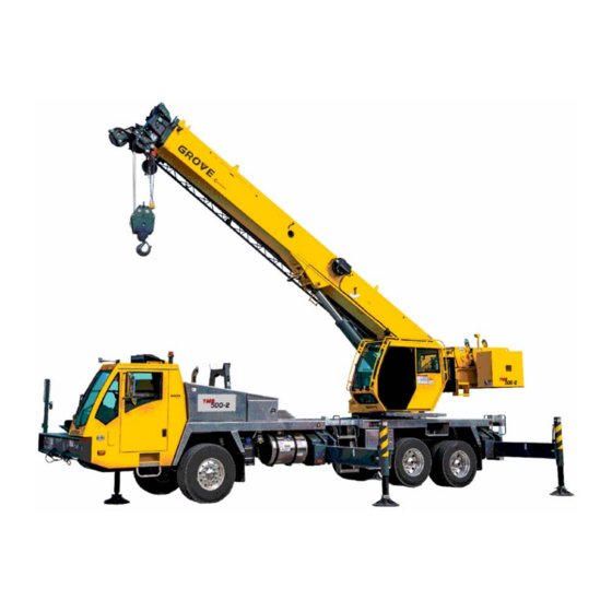
- Page 20 INTRODUCTION TMS500-2 OPERATOR MANUAL Main Exhaust After Carrier Cab Auxiliary Hoist Lift Cylinder Superstructure Treatment Battery Hoist Boom Nose Compartment Compartment DEF Tank Fuel Tank Rear Outriggers Front Outriggers Steering Axle Counterweight Center Front Jack Rear Drive Axles Cylinder 9827 Boom and Boom Extension Engine Compartment Air Cleaner...
- Page 21 TMS500-2 OPERATOR MANUAL INTRODUCTION LIST OF SPECIFICATIONS Engine Cummins ISL9-2017 General Bore ......114 mm (4.5 in) Model .
- Page 22 INTRODUCTION TMS500-2 OPERATOR MANUAL Telescoping* 7.92 or 13.70 meters (26 or 45 ft) *Extensions are offsettable at 0,15 or 30 degrees. Published 9-3-2021, Control # 672-04...
- Page 23 TMS500-2 OPERATOR MANUAL SAFETY INFORMATION SECTION 2 SAFETY INFORMATION SECTION CONTENTS Safety Messages......2-2 Grounding the Crane .
-
Page 24: Safety Messages
All damaged parts must be repaired or replaced as authorized CAUTION by your Grove distributor and/or Manitowoc Crane Care. Without the safety alert symbol, identifies hazards that could result in property damage if the message is ignored. -
Page 25: Operator Information
717-597-8121 OPERATOR QUALIFICATIONS Fax: 717-593-5152 E-mail: product.safety@manitowoc.com Qualified person is defined as one who by reason of knowledge, training and experience is thoroughly familiar OPERATOR INFORMATION with crane operations and the hazards involved. Such a person shall meet the operator qualifications specified in... -
Page 26: Operational Aids
SAFETY INFORMATION TMS500-2 OPERATOR MANUAL • You read, understand, and follow the safety and malfunctioning, the following requirements shall apply for o p e r a t i n g r e c o m m e n d a t i o n s c o n t a i n e d i n t h e continued use or shutdown of the crane: manufacturer’s manuals, your employer’s work rules, •... -
Page 27: Anti-Two-Blocking Device
TMS500-2 OPERATOR MANUAL SAFETY INFORMATION NEVER exceed the rated capacity shown on the Load Chart. intended to assist the operator in preventing dangerous two- Always check the Load Chart to make sure that the load to block conditions. It is not a replacement for operator be lifted at the desired radius is within the rated capacity of awareness and competence. -
Page 28: Crane Stability/Structural Strength
SAFETY INFORMATION TMS500-2 OPERATOR MANUAL CRANE STABILITY/STRUCTURAL Before swinging the superstructure over the side when the outriggers are retracted, check for backwards stability under STRENGTH the sub-section titled Model Specific Information later in this To avoid death or serious injury, make sure that the crane is section. -
Page 29: Load Charts
TMS500-2 OPERATOR MANUAL SAFETY INFORMATION Work Site Prior to any operation, you must inspect the entire work site, including ground conditions, where the crane will travel and operate. Make sure that the surfaces will support a load greater than the crane’s weight and maximum capacity. Be aware of all conditions that could adversely effect the stability of the crane. -
Page 30: Wind Speeds
SAFETY INFORMATION TMS500-2 OPERATOR MANUAL Table 2-1 Beaufort Wind Scale Maximum Wind Speed Beaufort Visible Indicator Description km/h Number Effects of wind as observed on land Zero (0) Calm Calm; smoke rises vertically Smoke drift indicates wind direction. Leaves and wind vanes Light Air are stationary. - Page 31 TMS500-2 OPERATOR MANUAL SAFETY INFORMATION Simplified Method to Determine Maximum Permissible Wind Speed Determine 3-Second Gust 0.14 V(z) = [(z/10) + 0.4]v [m/s] Wind Speed at boom tip, 0.14 V(z) = [(z/33) + 0.4]v [mph] V(z) 13.4 m/s < V(z) < 20.1 m/s V(z) >...
-
Page 32: Determination Of 3-Second Wind Gust Speed At Boom Tip Height
SAFETY INFORMATION TMS500-2 OPERATOR MANUAL Determination of 3-second wind gust speed at boom than 0.0012 square meters per kilogram (0.0059 sq.ft per pound of load. (See below Formulas 2.4 and 2.5.) tip height: The load capacities shall be reduced to account for the larger The following example illustrates how to calculate 3-second wind resistance area of load and 3-second wind gust speed wind gust speed at boom tip height based on mean wind... -
Page 33: Determining Wind Drag Coefficient (Cd)
TMS500-2 OPERATOR MANUAL SAFETY INFORMATION Calculation of Projected Wind Area (Ap) Wind Wind = 8 m = 24 m 25 ft 25 ft Wind Wind 10 ft 3 ft = 75 ft = 250 ft 10 ft 3 ft 8384-1 FIGURE 2-2 Determining Wind Drag Coefficient (Cd) Table 2-2 shows the typical Shapes and corresponding Wind... - Page 34 SAFETY INFORMATION TMS500-2 OPERATOR MANUAL Table 2-2 Wind Drag Coefficient Shape 1.1 to 2.0 0.3 to 0.4 0.6 to 1.0 0.8 to 1.2 0.2 to 0.3 0.05 to 0.1 Turbine Blade or Complete Rotor Approximately 1.6 8384-2 Maximum Permissible Wind Speed If the wind resistant area of the load Awr is greater than (load)
- Page 35 TMS500-2 OPERATOR MANUAL SAFETY INFORMATION Rated Load Chart Example - Metric 8383-1 FIGURE 2-3 Grove 2-13 Published 9-3-2021, Control # 672-04...
- Page 36 SAFETY INFORMATION TMS500-2 OPERATOR MANUAL Table 2-4 Example-Capacity Reduction Factors for Wind Speed V(z) Greater than 13.4 m/s - Metric (Only for lifting with main boom on fully extended outriggers, with or without stowed extension) For wind speed V(z) (3-second gust speed at boom tip height) V(z) > 13.4 m/s ≤ 20.1 m/s, the Reduced Capacity shall be calculated by multiplying the Published Rated Capacity by the following factors: Main Boom Length in Meters Wind Speed...
- Page 37 TMS500-2 OPERATOR MANUAL SAFETY INFORMATION This reduced capacity load has an allowable wind resistance Refer to the above Lifting Limits at V(z) > 13.4 m/s area of: and ≤ 20.1 m/s. Comparing the load and wind resistant area to the allowable: = 0.0012 x 12,040 = 14.45 m (allow) •...
- Page 38 SAFETY INFORMATION TMS500-2 OPERATOR MANUAL • Load to be lifted of 8,000 kg, • Is Awr less than Awr (load) (allow) 19.83 m ≤ 14.45 m • Projected Wind Area Ap = 15.25 m Conclusion: This load is NOT permissible to lift in wind •...
- Page 39 TMS500-2 OPERATOR MANUAL SAFETY INFORMATION Rated Load Chart Example - Non-metric 8382-1 FIGURE 2-4 Grove 2-17 Published 9-3-2021, Control # 672-04...
-
Page 40: Example And Sample Calculations (Non-Metric)
SAFETY INFORMATION TMS500-2 OPERATOR MANUAL Table 2-6 Example-Capacity Reduction Factors for Wind Speed V(z) Greater than 30 mph - Non-metric (Only for lifting with main boom on fully extended outriggers, with or without stowed extension) For wind speed Vz (3-second gust speed at boom tip height) is greater > 30> mph ≤ 45 mph, the Reduced Capacity shall be calculated by multiplying the Published Rated Capacity by the following factors: Main Boom Length in Feet Wind Speed... - Page 41 TMS500-2 OPERATOR MANUAL SAFETY INFORMATION The maximum allowable wind resistance area of load is: • Load to be lifted of 18,000 lb, = 0.0059 x m (2.5) (allow) (load) • Projected Wind Area Ap = 45 ft = 0.0059 x 25,200 = 149 ft (allow) •...
-
Page 42: Lifting Operations
SAFETY INFORMATION TMS500-2 OPERATOR MANUAL From Table 2-7, the maximum permissible wind speed at Verify the crane’s capacity by checking the Load Chart ratio of 1.45 (rounded to next higher table value of 1.6) is against the weight of the load. Then, lift the load slightly at 23.7 mph. -
Page 43: Multiple Crane Lifts
TMS500-2 OPERATOR MANUAL SAFETY INFORMATION Do not strike any obstruction with the boom. If the boom 1926.753(e)(1) A multiple lift shall only be performed if the should accidentally contact an object, stop immediately. following criteria are met: Inspect the boom. Remove the crane from service if the •... -
Page 44: Outrigger Lift Off
SAFETY INFORMATION TMS500-2 OPERATOR MANUAL Therefore, the following additional precautions must be government regulations, industry standards, local and job- taken if it is necessary for the crane to be used to perform tilt- site rules and employer policies so a thorough knowledge of up panel lifting using a crane equipped with two hoists: and compliance with all relevant work rules is necessary. -
Page 45: Crane Equipment
TMS500-2 OPERATOR MANUAL SAFETY INFORMATION It is not the intention of Grove to recommend specific types • All hoist hooks shall be equipped with a positive or makes of pile driving and pile extraction equipment, but locking latch. rather to advise of the operational requirements to help avoid Crane Inspection the detrimental effects that pile driving and pile extraction can have on the crane. -
Page 46: Set-Up And Operation
SAFETY INFORMATION TMS500-2 OPERATOR MANUAL Crane operation is dangerous when close to an energized The safest way to avoid electrocution is to stay away from electrical power source. Exercise extreme caution and electrical power lines and electrical power sources. prudent judgement. Operate slowly and cautiously when in It is not always necessary to contact a power line or power the vicinity of power lines. -
Page 47: Electrocution Hazard Devices
TMS500-2 OPERATOR MANUAL SAFETY INFORMATION boom nose and a small portion of the boom. Performance of boom cages and boom guards is limited by their physical size, insulating characteristics, and operating environment (e.g. dust, dirt, moisture, etc.). The insulating characteristics of these devices can be compromised if not kept clean, free of contamination, and undamaged. -
Page 48: Special Operating Conditions And Equipment
Thoroughly inspect the hoist rope and all points of contact on the crane. Should the distributor not be • Near high-frequency switching stations immediately available, contact Manitowoc Crane Care. The • If a thunder storm is forecast crane must not be returned to service until it is thoroughly inspected for any evidence of damage and all damaged parts Use electrically conducting material for grounding. -
Page 49: Personnel Handling
TMS500-2 OPERATOR MANUAL SAFETY INFORMATION PERSONNEL HANDLING • The crane operator and occupants have been instructed in the recognized hazards of personnel platform lifts. The American Society of Mechanical Engineers published • The crane is in proper working order. the American National Standard entitled, Personnel Lifting Systems, ASME B30.23: •... -
Page 50: Environmental Protection
SAFETY INFORMATION TMS500-2 OPERATOR MANUAL The following standards and regulations regarding personnel Always perform a function check after repairs have been handling are available by mail at the following addresses: made to ensure proper operation. Load tests should be performed when structural or lifting members are involved. •... -
Page 51: Moving Parts
To relieve hydraulic pressure, stop the engine, turn the ignition switch to RUN and move the • Consult with Manitowoc Crane Care to determine if load hydraulic controls in both directions several times. testing is required after a structural repair is performed. -
Page 52: Hoist Rope
Hoist rope may be purchased by contacting • If an operator hoists the hook block up or down too fast Manitowoc Crane Care. when reeved with multiple parts of line and no hook load, the wire rope can bird cage and damage the rope. -
Page 53: Sheaves
TMS500-2 OPERATOR MANUAL SAFETY INFORMATION ASME and similar organizations. See the Service • Operate the new rope—first through several cycles at Manual for inspection procedures. light load—then through several cycles at intermediate load, to allow the rope to adjust to operating conditions. When inspecting ropes and attachments, keep all parts of your body and clothing away from rotating hoist drums When using a wedge socket... -
Page 54: Batteries
SAFETY INFORMATION TMS500-2 OPERATOR MANUAL upon the user’s experience and the demands of his Make sure that the key switch has been off for application. 2 minutes. Turn the battery disconnect switch to the OFF position. Batteries Remove the ECM power fuse. Battery electrolyte must not be allowed to contact the skin or eyes. -
Page 55: Travel Operation
TMS500-2 OPERATOR MANUAL SAFETY INFORMATION Do not use the dead end lug (1, Figure 2-8) on the boom ground, may create a bouncing effect that can result in loss nose for tying down the boom during transport. Damage to of control. If bouncing occurs, reduce travel speed. the lug and boom can result from usage as a tie down point. -
Page 56: Work Practices
SAFETY INFORMATION TMS500-2 OPERATOR MANUAL Slopes Do not walk on a surface if slip-resistant material is missing or excessively worn. Pick and carry on level surfaces only. Do not use the top of the boom as a walkway. Refer to the Operation Section for more detailed information on traveling on slopes. -
Page 57: Working
TMS500-2 OPERATOR MANUAL SAFETY INFORMATION Working Operate the crane only from the operator’s seat. Do not reach in a window or door to operate any controls. Operator shall be responsible for all operations under his/her Operate the crane slowly and cautiously, looking carefully in direct control. -
Page 58: Hand Signals
SAFETY INFORMATION TMS500-2 OPERATOR MANUAL Make sure good rigging practices are being used. Refuse to Do not subject crane to side loading. A side load can tip the use any poorly maintained or damaged equipment. Never crane or cause it to fail structurally. wrap the hoist cable around a load. - Page 59 TMS500-2 OPERATOR MANUAL SAFETY INFORMATION Reprinted from ASME B30.5-2014, by permission of The American Society of Mechanical Engineers. All Rights Reserved. FIGURE 2-10 8496-3 Grove 2-37 Published 9-3-2021, Control # 672-04...
-
Page 60: Boom Extension
SAFETY INFORMATION TMS500-2 OPERATOR MANUAL BOOM EXTENSION boom and boom extension of a crane to be fully lowered to the ground. When a qualified person at a jobsite determines To avoid death or serious injury, follow the procedures in this that it is not practical to lower the boom to the ground, we m a n u a l d u r i n g e r e c t i o n , s t o w a g e , a n d u s e o f t h e recommend the following additional instructions be followed:... -
Page 61: Temperature Effects On Hook Blocks
TMS500-2 OPERATOR MANUAL SAFETY INFORMATION Plastic components (battery casings, heater controls, dash allow a cylinder to retract as the hydraulic fluid which is controls, etc.) are extremely brittle in extreme cold. Use trapped in the cylinder cools. caution handling and operating these components in sub- The change in the length of a cylinder is proportional to the zero temperatures, avoiding shock loading. - Page 62 SAFETY INFORMATION TMS500-2 OPERATOR MANUAL Table 2-8: Boom Drift Chart (Cylinder length change in inches) Coeff. = 0.00043 (in / °F) STROKE Temperature Change (°F) (FT.) 0.26 0.52 0.77 1.03 1.29 1.55 1.81 2.06 2.32 2.58 0.52 1.03 1.55 2.06 2.58 3.10 3.61...
-
Page 63: Model Specific Information
Perform the inspections outlined in this publication crane operation must be stopped immediately and Your for overloads up to 50%. Local Distributor or Manitowoc Crane Care must be contacted for corrective action. • Stop operating the crane and contact Your Local... -
Page 64: Boom Inspection
SAFETY INFORMATION TMS500-2 OPERATOR MANUAL Boom Inspection 9826 9827-1 FIGURE 2-11 Illustration for reference only. Your crane may be different. 2-42 Published 9-3-2021, Control # 672-04... - Page 65 TMS500-2 OPERATOR MANUAL SAFETY INFORMATION Overload less than 25% Sheaves Inspect all for damage. Overload from 25% to 49% Sheaves Inspect all for damage. Collar-welds Inspect all for cracks. Telescopic Inspect for bent or twisted sections. Check the boom Sections for straightness.
-
Page 66: Superstructure Inspection
SAFETY INFORMATION TMS500-2 OPERATOR MANUAL Superstructure Inspection 9826 9827-1 Illustration for reference only. Your crane may be different. FIGURE 2-12 2-44 Published 9-3-2021, Control # 672-04... - Page 67 TMS500-2 OPERATOR MANUAL SAFETY INFORMATION Overload less than 25% Lift Cylinder Inspect for leaking. Turntable See topic in Swing section of Check bolts for proper torque. Bearing Service Manual. See topic in Introduction section Wire Rope Inspect all for damage. of Service Manual.
-
Page 68: Carrier Inspection
SAFETY INFORMATION TMS500-2 OPERATOR MANUAL Carrier Inspection FIGURE 2-13 9826 Illustration for reference only. Your crane may be different. 2-46 Published 9-3-2021, Control # 672-04... - Page 69 TMS500-2 OPERATOR MANUAL SAFETY INFORMATION Overload less than 25% Jack Cylinders Inspect for leaking. Outrigger Inspect for deformation and cracked welds. Pads Overload from 25% to 49% Jack Cylinders Inspect for leaking. Outrigger Inspect for deformation and cracked welds. Pads Outrigger Inspect for deformation and cracked welds.
- Page 70 SAFETY INFORMATION TMS500-2 OPERATOR MANUAL This Page Blank 2-48 Published 9-3-2021, Control # 672-04...
- Page 71 TMS500-2 OPERATOR MANUAL OPERATING CONTROLS AND INDICATORS SECTION 3 OPERATING CONTROLS AND INDICATORS SECTION CONTENTS Carrier Cab Controls and Indicators ... 3-4 Tire Inflation Switch ..... . . 3-10 Transmission Shift Lever .
- Page 72 OPERATING CONTROLS AND INDICATORS TMS500-2 OPERATOR MANUAL Seat Belt Unfastened Indicator ....3-16 Crane Function Enable/Disable Switch ..3-25 Hoist Bypass Switch ..... . 3-25 Outrigger Controls and Indicators .
- Page 73 TMS500-2 OPERATOR MANUAL OPERATING CONTROLS AND INDICATORS Operator Display Module (ODM) ... . 3-33 WRL - Virtual Walls Limitation Function ..3-50 Errors (Fault Code) Group Menu ... . . 3-50 Navigation Control Pad .
-
Page 74: Carrier Cab Controls And Indicators
OPERATING CONTROLS AND INDICATORS TMS500-2 OPERATOR MANUAL CARRIER CAB CONTROLS AND INDICATORS See Figure 3-3 1. Transmission Shift Lever 2. Spare 3. Spare 4. Spare 5. USB Ports 6. 12 Volt Outlet 7. Fire Extinguisher 8. Horn 9. Turn Signal/High Beam-Low Beam Lever 10. -
Page 75: Transmission Shift Lever
TMS500-2 OPERATOR MANUAL OPERATING CONTROLS AND INDICATORS Transmission Shift Lever Windshield Wiper and Washer The transmission shift lever (1), (Figure 3-1) is located on the The windshield wiper and washer (12), (Figure 3-1) removes right side of the cab. It is used to select the transmission moisture from the windshield. -
Page 76: Steering Wheel Controls
OPERATING CONTROLS AND INDICATORS TMS500-2 OPERATOR MANUAL Cruise Control ON/OFF Switch can be lowered to protect the occupants’ eyes from bright sunlight. The Cruise Control ON/OFF Switch (7), (Figure 3-2) is located on the steering wheel and is a system that STEERING WHEEL CONTROLS automatically controls the speed of the vehicle. - Page 77 TMS500-2 OPERATOR MANUAL OPERATING CONTROLS AND INDICATORS 8872 1. Flash Marker Lights Switch 2. Windshield Washer 3. Intermittent Wiper Speed Control 4. Windshield Wiper Off 5. High/Low Wiper Speed Control 6. Horn Switch 7. Cruise Control On/Off Switch 8. Cancel Set Speed Switch 9.
-
Page 78: Headlights Switch
OPERATING CONTROLS AND INDICATORS TMS500-2 OPERATOR MANUAL 1. Headlights Switch 14. Cross-Axle Lock Switch (Optional) 2. Dimmer Switch 15. Suspension Inflation Switch 3. Beacon Light Switch (Optional) 16. Tire Inflation Switch 17. Heater/Air Conditioner Fan Speed Switch 4. Engine Brake ON/OFF Switch 5. -
Page 79: Exhaust System Cleaning Initiate Switch
TMS500-2 OPERATOR MANUAL OPERATING CONTROLS AND INDICATORS Hill Start Aid (HSA) System the top of the switch is pushed, the switch is in the high position and braking effort is at 100%. When the switch is in The Hill Start Aid (HSA) System (11), (Figure 3-3) is located the low position, it gives 50% braking effort. -
Page 80: Tire Inflation Switch
OPERATING CONTROLS AND INDICATORS TMS500-2 OPERATOR MANUAL Tire Inflation Switch Pressing the left side of the switch turns on the heater system and pressing the right side of the switch turns on the The Tire Inflation Switch (16), (Figure 3-3) is located on the air conditioner system. -
Page 81: Control Panel Indicator And Gauge Display
TMS500-2 OPERATOR MANUAL OPERATING CONTROLS AND INDICATORS CONTROL PANEL INDICATOR AND GAUGE DISPLAY As a system check, the indicators will come on for two seconds when the ignition switch is turned to the RUN position. FIGURE 3-5 8861b (Figure 3-5) Item Numbers Item Description Low Oil Pressure Indicator... -
Page 82: Cross-Axle Lock Indicator (Optional)
OPERATING CONTROLS AND INDICATORS TMS500-2 OPERATOR MANUAL Cross-Axle Lock Indicator (Optional) Marker Lights ON Indicator The Cross-Axle Lock Indicator (1), (Figure 3-5) is located at The Marker Lights ON Indicator (7), (Figure 3-5) is located the left side of the gauge cluster. The amber indicator on the left side of the gauge cluster. -
Page 83: Anti-Lock Braking System (Abs) Indicator
ON. The amber indicator will remain ON until the brake or by contacting Manitowoc Crane Care. pedal has been pressed and the system senses the activation. -
Page 84: High Exhaust System Temperature Indicator
OPERATING CONTROLS AND INDICATORS TMS500-2 OPERATOR MANUAL High Exhaust System Temperature Indicator Up Button The High Exhaust System Temperature (HEST) Indicator The Up Button (31), (Figure 3-5) is used to scroll up through (26), (Figure 3-5) is located in the tachometer. the screens on the LCD. -
Page 85: Wait To Start Indicator
TMS500-2 OPERATOR MANUAL OPERATING CONTROLS AND INDICATORS cycle. When the Cleaning Switch (6),(Figure 3-3) is • Pressing the Up/Down buttons will scroll the Reset Trip momentarily placed in the manual cleaning position, manual A/Reset Trip B/Units/Brightness/Software Version. With cleaning is initiated. the Units option displayed, pressing and holding the OK button will reset the Units value. -
Page 86: Seat Belt Unfastened Indicator
OPERATING CONTROLS AND INDICATORS TMS500-2 OPERATOR MANUAL Seat Belt Unfastened Indicator Item Description The Seat Belt Unfastened Indicator (36), (Figure 3-5) is Trip A Distance Traveled located in the tachometer. The indicator illuminates when the Trip B Distance Traveled ignition is on and the seat belt is not fastened. A buzzer will Voltmeter sound until the seat belt is fastened. -
Page 87: Outrigger Controls And Indicators
TMS500-2 OPERATOR MANUAL OPERATING CONTROLS AND INDICATORS OUTRIGGER CONTROLS AND INDICATORS outriggers. The numbers in parentheses ( ) represent the index number from the outrigger panel illustration. The following paragraphs describe the additional controls and indicators located on the carrier to operate the FIGURE 3-7 8866 extending and retracting the outrigger beams on that side of... -
Page 88: Extend Switch
OPERATING CONTROLS AND INDICATORS TMS500-2 OPERATOR MANUAL Extend Switch Retract Switch The Extend Switch (3), (Figure 3-7) will operate both the The Retract Switch (7), (Figure 3-7) will operate both the outrigger beams or the jacks. After pushing the desired outrigger beams or the jacks. -
Page 89: Superstructure Cab
TMS500-2 OPERATOR MANUAL OPERATING CONTROLS AND INDICATORS SUPERSTRUCTURE CAB Foot Pedals This section shows the position and designations of the For a description of the foot pedals (1), (Figure 3-8), refer to operating elements for crane operation. This also includes Foot Pedal Controls, page 3-25. -
Page 90: Superstructure Cab Overhead Controls
OPERATING CONTROLS AND INDICATORS TMS500-2 OPERATOR MANUAL SUPERSTRUCTURE CAB OVERHEAD CONTROLS FIGURE 3-12 9842 Item Description Skylight Window Latch Skylight Wiper Skylight Sunscreen Dome Light FIGURE 3-9 9506a Cab Circulating Fan Right Side Window Latch Emergency Stop Switch Overhead Control Panels Radio (Optional) Diesel Fired Cab Heater Controls (Optional) Work Lights Switch... -
Page 91: Skylight Sunscreen
TMS500-2 OPERATOR MANUAL OPERATING CONTROLS AND INDICATORS Skylight Sunscreen Work Lights Switch The Skylight Sunscreen (3), (Figure 3-9) is located toward The Work Lights Switch (11), (Figure 3-9) controls the the rear of the window. It is used to diminish direct sunlight. crane’s work lights mounted on the bottom front of the The sunscreen is self retracting and can be set to screen all superstructure cab. -
Page 92: Rcl External Light Tower (Optional)
OPERATING CONTROLS AND INDICATORS TMS500-2 OPERATOR MANUAL RCL External Light Tower (Optional) If using a jib, the anemometer assembly should be relocated to the end of the jib to ensure accurate wind speed readings. The Rated Capacity Limiter (RCL) External Light Tower If not in use, the anemometer should be stored in the (Figure 3-14) is located on the outside upper right hand operator cab. -
Page 93: Installing The Anemometer Assembly
TMS500-2 OPERATOR MANUAL OPERATING CONTROLS AND INDICATORS Re-install the cotter pin (3), (Figure 3-16) on the rod (2), Stowing the Anemometer Assembly for Travel (Figure 3-16). Loosen the clamp bolt (6), (Figure 3-16). Installing the Anemometer Assembly Rotate the anemometer and mast assembly (1), (Figure 3-16) towards rear of the crane until the mast is Use the following procedure to install the anemometer horizontal. -
Page 94: Superstructure Overhead Control Panel
OPERATING CONTROLS AND INDICATORS TMS500-2 OPERATOR MANUAL SUPERSTRUCTURE OVERHEAD CONTROL Washer is controlled by the Windshield Washer Switch (2) (Figure 3-18). PANEL Skylight Wiper Switch The Skylight Wiper Switch (3), (Figure 3-18) is used to turn the wiper motor on and off. NOTE: A wiper delay interval may be set using the ODM (see Setting the Wiper Interval Function, page 4-... -
Page 95: Wait-To-Start Indicator
TMS500-2 OPERATOR MANUAL OPERATING CONTROLS AND INDICATORS once to go to full engine speed; quickly press the bottom of • Anti-two Block Lockout the switch once to return to low engine idle. If the engine • Minimum Wrap Lockout speed is below the maximum speed setting, pressing and holding the top of the switch will cause the engine speed to Working Range Limiter (WRL) System slowly increase;... -
Page 96: Swing Brake Pedal
OPERATING CONTROLS AND INDICATORS TMS500-2 OPERATOR MANUAL Swing Brake Pedal 360° Swing Lock Release Lever (Optional) The Swing Brake Pedal (3), (Figure 3-19) is located on the The 360° Swing Lock Release Lever (5), (Figure 3-19) is left side of the cab floor. It actuates the swing brake to slow located on the left side of the cab floor, directly above the or stop swing motion. -
Page 97: Control Seat Assembly
TMS500-2 OPERATOR MANUAL OPERATING CONTROLS AND INDICATORS CONTROL SEAT ASSEMBLY 8044-2a FIGURE 3-20 Item Description Right Hand Arm Rest Controls Right Hand Arm Rest Controls Refer to the Right Hand Arm Rest Controls, page 3-30. Left Hand Arm Rest Controls Left Hand Arm Rest Controls Horn Refer to the Left Hand Arm Rest Controls, page 3-27. -
Page 98: Seat Slide Lever
OPERATING CONTROLS AND INDICATORS TMS500-2 OPERATOR MANUAL Seat Slide Lever equipped with Dual Axis Controllers. Refer to Deadman Switches (Dual Axis - Controllers Only), page 3-27. Pressing Moving the Seat Slide Lever (6), (Figure 3-20) will enable a Deadman Switch allows the crane functions to remain only the seat to slide, either forward or backward. -
Page 99: Swing/Telescope Or Swing/Auxiliary Hoist Control Lever (Dual Axis)
TMS500-2 OPERATOR MANUAL OPERATING CONTROLS AND INDICATORS Swing/Telescope or Swing/Auxiliary Hoist Outrigger Extend/Retract Switch Control Lever (Dual Axis) The Outrigger Extend/Retract Switch (4), (Figure 3-22) allows the operator to switch between extension/retraction of the outrigger beams and raising/lowering of the jacks. Press and hold this switch to force the ODM to change to the DANGER outrigger page. -
Page 100: Rcl Bypass Switch
OPERATING CONTROLS AND INDICATORS TMS500-2 OPERATOR MANUAL RCL Bypass Switch All craning functions locked out are bypassed when this key switch has been actuated and bypass mode becomes active. Overriding the RCL with this switch should only be done by a qualified operator or technician. -
Page 101: Boom Lift/Main Hoist Control Lever (Dual Axis)
TMS500-2 OPERATOR MANUAL OPERATING CONTROLS AND INDICATORS Boom Lift Function Enable/Disable Switch Boom Lift Function Enable/Disable Switch The Boom Lift Function Enable switch (5), (Figure 3-24) is a Main Hoist Enable/Disable Switch momentary switch that enables boom up and boom down. Boom Lift/Main Hoist Control Lever (Dual Press once to enable boom lift and press again to disable the boom lift switch. -
Page 102: Main Hoist Controller (Single Axis Option)
OPERATING CONTROLS AND INDICATORS TMS500-2 OPERATOR MANUAL MAIN HOIST CONTROLLER (SINGLE AXIS OPTION) Right Side Left Side 9885 Item Description Main Hoist Controller (Single Axis Option) Boom Lift Controller (Single Axis Option) Boom Telescope or Auxiliary Hoist Controller (Single Axis Option) Swing Controller (Single Axis Option) Jog Dial FIGURE 3-25... -
Page 103: Swing Controller (Single Axis Option)
TMS500-2 OPERATOR MANUAL OPERATING CONTROLS AND INDICATORS Swing Controller (Single Axis Option) Item Description Navigation Control Pad The Swing Control Lever (4), (Figure 3-25)) is located on the USB Connector left armrest. Pushing the controller forward rotates the superstructure clockwise and pulling the controller rearward RCL Shutdown Warning Indicator r o t a t e s t h e s u p e r s t r u c t u r e c o u n t e r c l o c k w i s e . -
Page 104: Usb Connector
OPERATING CONTROLS AND INDICATORS TMS500-2 OPERATOR MANUAL Refer to Navigating the Operator Display Module (ODM) and Rated Capacity Limiter (RCL) Display Module, page 4-37 for information on how the Navigational Control Pads and Jog Dial are used in the operation of the crane. USB Connector A USB Connector (4), (Figure 3-26) is provided for the Rated Capacity Limiter Display Module (RDM) and the Operator... -
Page 105: Minimum Wrap Limiter System Indicator (Optional)
TMS500-2 OPERATOR MANUAL OPERATING CONTROLS AND INDICATORS occurs, the crane control system will lock out the hoist up, Temperature Warning Indicator will come on (blue) and the boom down, and telescope out crane functions, which would module’s screen will remain blank. When the ignition key worsen the two-block condition. -
Page 106: Ignition Switch
OPERATING CONTROLS AND INDICATORS TMS500-2 OPERATOR MANUAL Ignition Switch out, the pin is pulled out of the socket, unlocking the superstructure.Rotate the Turntable Swing Lock Handle to The Ignition Switch (1), (Figure 3-30) is located on the lower release the lock on the cable. Pull the handle to release the right side of the front console. - Page 107 TMS500-2 OPERATOR MANUAL OPERATING CONTROLS AND INDICATORS FIGURE 3-32 8882a Example: Camera Views 1 and 2 Displayed on Main Screen Grove 3-37 Published 9-3-2021, Control # 672-04...
- Page 108 OPERATING CONTROLS AND INDICATORS TMS500-2 OPERATOR MANUAL Item Item Description Engine Speed Display Displays current engine speed Voltage Monitoring Display Displays system voltage Coolant Temperature Display Displays engine coolant temperature DEF Level Displays amount of DEF in reservoir tank Indicates exhaust system cleaning function is Exhaust System Cleaning Inhibited prevented Exhaust System Cleaning Needed...
-
Page 109: Alert Icons
TMS500-2 OPERATOR MANUAL OPERATING CONTROLS AND INDICATORS Alert Icons Name Icon Description The following Alert Icons can appear on the ODM Main The engine coolant Engine Screen when an error is present during the operation of the temperature is high. temperature crane. - Page 110 OPERATING CONTROLS AND INDICATORS TMS500-2 OPERATOR MANUAL Name Icon Description Name Icon Description The battery voltage is Only 3 wraps remain Alternator too low (about 22V or Minimum wrap on the aux hoist. Hoist charge low less) or too high (30V aux.
- Page 111 TMS500-2 OPERATOR MANUAL OPERATING CONTROLS AND INDICATORS Name Icon Description Settings Speed Joystick curve/speed not at default. RCL Bridging Mode NonEn Switch is Active. Switch Grove 3-41 Published 9-3-2021, Control # 672-04...
-
Page 112: Status Bar Icons
OPERATING CONTROLS AND INDICATORS TMS500-2 OPERATOR MANUAL Status Bar Icons The following Status Bar Icons can appear in the Status Bar (3), (Figure 3-32) area of the ODM Main Screen: Description Graphic Explanation Swing Disabled Indicates the swing function is disabled (refer to Crane Function Enable/ Indicator Disable Switch, page 3-25 and Swing Enable/Disable Switch, page 3-29). - Page 113 TMS500-2 OPERATOR MANUAL OPERATING CONTROLS AND INDICATORS Description Graphic Explanation Indicates the boom lift function is disabled (refer to Crane Function Enable/ Boom Lift Disabled Disable Switch, page 3-25 and Boom Lift Function Enable/Disable Switch, Indicator page 3-31). Indicates the boom lift function is enabled, but is in a standby mode due to the operator not being seated (causing seat switch to open).
-
Page 114: Operating Elements Of The Crane Control System (Ccs)
OPERATING CONTROLS AND INDICATORS TMS500-2 OPERATOR MANUAL Description Graphic Explanation Main Hoist High Speed Indicates the main hoist function and the high speed function are enabled. Indicator (Green) Auxiliary Hoist Indicates the auxiliary hoist (optional) function is disabled (refer to Crane Disabled Indicator Function Enable/Disable Switch, page 3-25 and Auxiliary Hoist Enable/ (Optional) -
Page 115: General Rules For Buttons And Symbols On The Ccs Display
TMS500-2 OPERATOR MANUAL OPERATING CONTROLS AND INDICATORS Boom Nose Over Rear FIGURE 3-35 8854-128d For the ODM crane function status, the possibilities are: • Not Enabled: Navy Blue background, orange icon (this is at the first key on without pushing any buttons). 8854-56 •... -
Page 116: Exiting The Menu/Input Mode
OPERATING CONTROLS AND INDICATORS TMS500-2 OPERATOR MANUAL While on the ODM Home Screen (1),(Figure 3-36) and scrolling so that the 'menu' icon is selected (as shown with Turn the the orange icon) and select 'OK' display button or with the jog dial, the Main Menu screen will appear (2), (Figure 3-36). -
Page 117: Input Confirmation
TMS500-2 OPERATOR MANUAL OPERATING CONTROLS AND INDICATORS Input Confirmation 28) indicates the Active Screen. Item 2, (Figure 3-39) indicates the Menu Screen. The additional menu items are An input can be confirmed with Button (6), (Figure 3-28) or listed in Figure 3-39 and on the following Table. Button (5), (Figure 3-27) labeled OK as shown on page 3-34. - Page 118 OPERATING CONTROLS AND INDICATORS TMS500-2 OPERATOR MANUAL Item Description Item Description Active Screen Indicator Icon Crane Operation Function Icon Menu Screen Indicator Icon Engine Fault Function Icon Status Bar Indicator Icon Information Group Menu Icon Camera Group Menu Icon (Optional) Operating Hours Function Icon Camera View 1 Icon (Optional) Software Version Function Icon...
-
Page 119: Warning Message/Error Message Display Area
TMS500-2 OPERATOR MANUAL OPERATING CONTROLS AND INDICATORS Warning Message/Error Message Display Area Outrigger Function In the Warning Message/Error Message Display area (1) The Outrigger Menu is used to deploy and monitor the (Figure 3-40) error message icons will appear on the left side outriggers. -
Page 120: Wrl - Boom Height Limitation Function
OPERATING CONTROLS AND INDICATORS TMS500-2 OPERATOR MANUAL within. Refer to WRL - Boom Angle Limitation Menu, page 4- adjust parameters, set display options, and control functions. WRL - Boom Height Limitation Function The WRL Boom Height Limitation Function allows the operator to set a limit for the maximum boom height. -
Page 121: Tools User Settings Group Menu
TMS500-2 OPERATOR MANUAL OPERATING CONTROLS AND INDICATORS Tools User Settings Group Menu The Tools User Settings Group Menu is made up of the Setting the Time Zone; Display Brightness; and the Units of Measure Function. Refer to Tools User Settings Group Menu, page 4-80. -
Page 122: Superstructure Remote Drive Controls
OPERATING CONTROLS AND INDICATORS TMS500-2 OPERATOR MANUAL Table 3-10 10346 FIGURE 3-45 The movement of the joystick will be used to steer the front Item Component axle. Neutral Drive (Forward) Manual Mode Shift Down Shift Up Service Indicator 10347 Reverse FIGURE 3-46 Superstructure Remote Drive Controls Item... -
Page 123: Service Brake Pedal
TMS500-2 OPERATOR MANUAL OPERATING CONTROLS AND INDICATORS Service Brake Pedal NOTE: If the crane is set up on the outriggers, adjust the stabilizers so that they will not come into contact The service brakes (Figure 3-47) are actuated using the with the ground. -
Page 124: Truck Steering Operation
OPERATING CONTROLS AND INDICATORS TMS500-2 OPERATOR MANUAL Troubleshooting Truck Steering Operation With the Swing Function disabled and the Remote Drive Reference the table below for error indication when enabled, use the left joystick to steer the truck using the attempting to engage or while operating in Remote Drive same controller movement as swing. -
Page 125: Remote Control (Optional)
TMS500-2 OPERATOR MANUAL OPERATING CONTROLS AND INDICATORS Indicators Refer to the table below for indicators that are associated with the Remote Drive Mode. WARNING Tipping/Overload Hazard! RCL lockouts and limiters are not functional when remote Operator Display Module (ODM) Remote Drive control is used. - Page 126 OPERATING CONTROLS AND INDICATORS TMS500-2 OPERATOR MANUAL 9479e FIGURE 3-49 3-56 Published 9-3-2021, Control # 672-04...
- Page 127 TMS500-2 OPERATOR MANUAL OPERATING CONTROLS AND INDICATORS Table 3-11 Remote Control System Components Item Component (Figure 3-49) Description The remote control communicates with the receiver to control the crane functions identified in this publication. Remote Control (Transmitter) • Powered by a 3.2Ah Lithium-Po rechargeable battery •...
-
Page 128: Remote Control Components
OPERATING CONTROLS AND INDICATORS TMS500-2 OPERATOR MANUAL Remote Control Components FIGURE 3-50 Table 3-13 Remote Control Components Item Component (Figure 3-50) Description Programming Port For Grove factory authorized use only Color Display Displays information for the selected function Power Button ON/OFF switch which activates and deactivates the remote control Amber, solid = remote control in boot loader mode (ready to be programmed) -
Page 129: Display Components
TMS500-2 OPERATOR MANUAL OPERATING CONTROLS AND INDICATORS Momentary buttons that activate the selected function in the display: 5a - Outrigger beams 5b - Outrigger jacks 5c - Boom lift 5d - Option: Function Selector Buttons (qty 10) 5e - Horn (activates the superstructure horn) 5f - Escape: exits the selected function screen 5g - Information (software version/revision and crane serial number) 5h - Engine... -
Page 130: Preparing For Remote Control Operation
OPERATING CONTROLS AND INDICATORS TMS500-2 OPERATOR MANUAL Green = full charge Battery Power Amber = discharging Right Motion Command Depicts the operation that is controlled by the right motion command button White = neither enable button is depressed (function cannot be operated) Left Enable Right Enable Green = either enable button is depressed (function can be operated) -
Page 131: Operating Remote Control
TMS500-2 OPERATOR MANUAL OPERATING CONTROLS AND INDICATORS The MAIN screen appears. Then, turn off the remote control by pressing the power button on the top of the remote control. If you fail to perform this step the remote control will remain ON (not operable) and its battery will discharge. - Page 132 OPERATING CONTROLS AND INDICATORS TMS500-2 OPERATOR MANUAL FIGURE 3-55 -9782 3-62 Published 9-3-2021, Control # 672-04...
-
Page 133: Engine Start/Stop/Throttle
TMS500-2 OPERATOR MANUAL OPERATING CONTROLS AND INDICATORS Table 3-15 Engine Start/Stop/Throttle Function Screen Item Indicator Name Description 1a - Yellow = engine cannot be started or stopped due to a crane fault Engine (start/stop) Function 1b - Green = engine can be started or stopped 2a - Blue = engine cannot be stopped until either enable button is held down Stop Engine 2b - Green = engine can be stopped with left motion button... - Page 134 OPERATING CONTROLS AND INDICATORS TMS500-2 OPERATOR MANUAL FIGURE 3-56 -9782-1 3-64 Published 9-3-2021, Control # 672-04...
-
Page 135: Outrigger Beams
TMS500-2 OPERATOR MANUAL OPERATING CONTROLS AND INDICATORS Table 3-16 Outrigger Beams Function Screen Item Indicator Name Description 1a - Yellow = beams cannot be operated due to a crane fault 1b - Both left side beams will be operated 1c - Both right side beams will be operated Outrigger Beams 1d - Left front beam will be operated Function... - Page 136 OPERATING CONTROLS AND INDICATORS TMS500-2 OPERATOR MANUAL FIGURE 3-57 -9782-2 3-66 Published 9-3-2021, Control # 672-04...
-
Page 137: Outrigger Jacks
TMS500-2 OPERATOR MANUAL OPERATING CONTROLS AND INDICATORS Table 3-17 Outrigger Jacks Function Screen Item Indicator Name Description 1a - Yellow = jacks cannot be operated due to a crane fault 1b - All four jacks will be operated at same time 1c - Both left side jacks will be operated 1d - Both right side jacks will be operated Outrigger Jacks... - Page 138 OPERATING CONTROLS AND INDICATORS TMS500-2 OPERATOR MANUAL FIGURE 3-58 -9782-3 3-68 Published 9-3-2021, Control # 672-04...
-
Page 139: Hoist Control (Main And Aux)
TMS500-2 OPERATOR MANUAL OPERATING CONTROLS AND INDICATORS Table 3-18 Main/Aux Hoist Function Screen Item Indicator Name Description 1a - Yellow = main hoist cannot be operated due to a crane fault Main Hoist Function 1b - Green = main hoist can be operated 2a - Blue = main hoist cannot be operated until either enable button is held down Let Out (lower) 2b - Green = wire rope can be payed out from main hoist with left motion button... - Page 140 OPERATING CONTROLS AND INDICATORS TMS500-2 OPERATOR MANUAL 9782-4 FIGURE 3-59 Table 3-19 Boom Lift Function Screen Item Indicator Name Description 1a - Yellow = boom cannot be operated due to a crane fault Boom Lift Function 1b - Green = boom can be operated 2a - White = boom cannot be operated until either enable button is held down Boom Down 2b - Green = boom can be lowered with left motion button...
- Page 141 TMS500-2 OPERATOR’S MANUAL OPERATING PROCEDURES SECTION 4 OPERATING PROCEDURES SECTION CONTENTS Pre-Starting Checks ......4-4 Crane Warm-up Procedures ....4-12 Fuel Supply .
- Page 142 OPERATING PROCEDURES TMS500-2 OPERATOR’S MANUAL Recommended Crane Shutdown Procedures. . . 4-25 Module ........4-37 Superstructure Cab Platform .
- Page 143 TMS500-2 OPERATOR’S MANUAL OPERATING PROCEDURES Information Group Menu ....4-70 Exhaust System Cleaning Function ..4-80 Tools User Settings Group Menu .
-
Page 144: Pre-Starting Checks
OPERATING PROCEDURES TMS500-2 OPERATOR’S MANUAL PRE-STARTING CHECKS Diesel Exhaust Fluid (DEF) Supply A complete walk-around visual inspection of the crane Check Diesel Exhaust Fluid (DEF) level and make sure cap should always be made with special attention to structural is on tight. Level is checked on Control Panel Indicator in damage, loose equipment, leaks, or other conditions that carrier cab and ODM in superstructure cab. -
Page 145: Seat Belt
TMS500-2 OPERATOR’S MANUAL OPERATING PROCEDURES Seat Belt There is a sensor installed in each wheel. Since this is a Seat Belt Maintenance three-axle crane, all axles are monitored. The sensors transmit information to the EC-60™ Premium electronic Seat belt assemblies are maintenance-free; however, they control unit (ECU). -
Page 146: Abs Switch Operation
OPERATING PROCEDURES TMS500-2 OPERATOR’S MANUAL ABS Switch Operation Fully telescope boom out and back in at 75°, 35°, and 0° boom angles, ensuring all sections extend and retract The ABS/Traction Control Indicator (3), (Figure 3-5) is used properly. to diagnose system problems along with blink codes With boom fully retracted and at maximum boom angle, displayed on the ABS Indicator. - Page 147 TMS500-2 OPERATOR’S MANUAL OPERATING PROCEDURES length and angle. If the operator knows radius and tip height operator knows boom length and angle, they can quickly required for a specific lift, the angle and boom length can determine tip height and operating radius. quickly be determined from the range diagram.
- Page 148 OPERATING PROCEDURES TMS500-2 OPERATOR’S MANUAL 9895 EXAMPLE ONLY FIGURE 4-3 AXIS OF ROTATION BOOM ANGLE HORIZONTAL OPERATING RADIUS 9556-1 TERMS FOR REFERENCE FIGURE 4-4 EXAMPLE ONLY A lifting diagram is included for over-side, over-rear, and The load chart also gives weight reductions for Grove load over-front lifting areas.
-
Page 149: Engine Operation
TMS500-2 OPERATOR’S MANUAL OPERATING PROCEDURES NOTE: Information in the following paragraph is an Example only of how to compute a lift. Numbers CAUTION may not match load chart in the crane cab. Never crank engine for more than 30 seconds during an NOTE: Figures 4-2 and 4-3 are SAMPLE Charts ONLY. -
Page 150: Idling Engine
OPERATING PROCEDURES TMS500-2 OPERATOR’S MANUAL NOTE: An engine block heater and grid heater are feature is enabled) to approximately 1200 RPM when the provided to aid in cold-starting. following conditions are met for a period of 5 minutes: When starting from the Superstructure cab, make sure •... -
Page 151: Initiating The Manual Exhaust Cleaning Process
TMS500-2 OPERATOR’S MANUAL OPERATING PROCEDURES Filter Clogged Indicator and a severe engine derate will (ODM), will come on (amber) and the active and manual occur. modes of exhaust system cleaning are prevented. These above conditions can only occur if cleaning has been Shutdown Procedure inhibited or a manual cleaning was interrupted. -
Page 152: Auxiliary Cab Heater (Optional)
If in doubt of suitability for a specific fluid or lubricant, check dard hot water crane cab heater can also be turned on after with an authorized Grove distributor or Manitowoc Crane engine has started and is warmed to operating temperature. -
Page 153: Engine
Lubrication section of your crane’s Operator Manual, by contacting your local Grove distributor, or by Warm-up procedures are recommended at every startup and contacting Manitowoc Crane Care directly). Refer to required at ambient temperatures below 4°C (40°F). Standard Lubricants, page 5-3. -
Page 154: Driving The Crane
OPERATING PROCEDURES TMS500-2 OPERATOR’S MANUAL DANGER Roll Hazard! When operating the outrigger controls, as a precaution to keep the crane from rolling, apply the parking brake. The parking brake should be set before lowering the crane back to the ground. FIGURE 4-7 DRIVING THE CRANE To reduce slack in the belt, pull the belt out as you did in... -
Page 155: Securing The Superstructure For Travel
TMS500-2 OPERATOR’S MANUAL OPERATING PROCEDURES NOTE: When lowering the boom into the rest, once at 10 CAUTION degrees, make sure that the turntable lock pin is fully engaged before proceeding to set the boom Machine Damage Hazard! into the rest. Do not travel with an empty hook in a position where it can swing freely (except where noted). -
Page 156: Traveling - Towing/Pulling
OPERATING PROCEDURES TMS500-2 OPERATOR’S MANUAL Traveling — Towing/Pulling CAUTION Machine Damage Hazard! Grove recommends towing or pulling another vehicle with the optional pintle hook (if equipped) or by attaching at a point no higher than the pintle hook height, or severe damage may occur to the drivetrain. -
Page 157: Traveling On Slopes
TMS500-2 OPERATOR’S MANUAL OPERATING PROCEDURES NOTE: Do not use the lugs on the front bumper for pulling or towing. These are for the Hookblock tie-down only. CAUTION Machine Damage Hazard! It is recommended to attach cables/straps to the optional pintle hook (if equipped) or by attaching at a point no higher than the pintle hook height if being towed by another vehicle. -
Page 158: Slope Limitations - Fore/Aft Travel
OPERATING PROCEDURES TMS500-2 OPERATOR’S MANUAL • No loads may be supported by the boom (for example, For 7.9 m (26 ft) Boom Extension no pick and carry loads) while traversing a slope. Travel is permissible under the following conditions: • All cribbing or other non-standard accessories must be •... -
Page 159: Gear Display
TMS500-2 OPERATOR’S MANUAL OPERATING PROCEDURES Unlock Trigger Gear Shift (front of lever) Transition Up shift Button Successful Gear Current Gear Shift Solid Solid May Momentarily Flash 8871 FIGURE 4-11 Downshift The “DASH” Figure 4-12 indicates the transmission may be Button torque locked in gear. -
Page 160: Power Down
OPERATING PROCEDURES TMS500-2 OPERATOR’S MANUAL Select the desired mode and starting gear on the shift • A shift can be advanced by pressing the up/down console. buttons when the transmission is near the shift point. NOTE: The transmission will over-ride inappropriate start •... -
Page 161: Manual / Hold Mode
TMS500-2 OPERATOR’S MANUAL OPERATING PROCEDURES MANUAL / Hold Mode LOW Mode • The ability to restrict driver use of MANUAL mode is LOW mode should be used to maximize engine braking and configurable. The default setting for this configuration is minimize the use of the brake pedal. -
Page 162: Differential Control Switches
OPERATING PROCEDURES TMS500-2 OPERATOR’S MANUAL When stopped on an incline, the ABS system will apply the Position the appropriate differential lock(s) switch to the brakes on the rear axles. When pulling away again, it will OFF position while maintaining slow speed. keep the brakes applied until the transmission tells the ABS Let up momentarily on the accelerator to allow the shift. -
Page 163: Anti-Lock Brake System (Abs)
TMS500-2 OPERATOR’S MANUAL OPERATING PROCEDURES • When driving on slippery pavement or under icy situation, a signal is sent from the ECU to the appropriate conditions, alternately and smoothly apply and release ABS modulator valve to reduce braking pressure. During the brakes to prevent skidding. -
Page 164: Automatic Traction Control (Atc) Functional Overview
OPERATING PROCEDURES TMS500-2 OPERATOR’S MANUAL FIGURE 4-16 Automatic Traction Control (ATC) Functional • The ATC off-road switch (4), (Figure 4-16) allows greater wheel spin (more torque) when activated. It is intended Overview for adverse conditions, usually off-highway. The switch Just as ABS improves vehicle stability during braking, ATC turns on ATC off-road when pushed once and off when improves vehicle stability and traction during vehicle pushed a second time and whenever the system goes... -
Page 165: Thermal (Brake Heat) Protection
TMS500-2 OPERATOR’S MANUAL OPERATING PROCEDURES indicator lamp will flash slowly at a rate of 1.0 seconds on, 1.5 seconds off to notify the vehicle operator that the off-road mode is active. WARNING Pushing the switch again will turn off the ATC off-road mode. Never park the crane near holes, or on rocky or extremely Thermal (Brake Heat) Protection soft surfaces. -
Page 166: Craning Functions
OPERATING PROCEDURES TMS500-2 OPERATOR’S MANUAL Bubble Level Indicator Adjustment NOTE: To check and adjust Auto level refer to the Service Manual. The Bubble Level Indicator should be checked periodically. If it is suspected that the bubble level indicator is out of adjustment, verify and adjust the bubble level as follows: Position the crane on a firm, level surface. -
Page 167: Setting The Outriggers From The Superstructure Cab
TMS500-2 OPERATOR’S MANUAL OPERATING PROCEDURES Extend the outrigger jacks using the Outrigger Extend/Retract Switch and the Operator Display Module. WARNING Extend each outrigger jack until the jack cylinder barrel Be sure the outriggers are properly extended and set, engages the pad and insert retaining pin. including the center front outrigger jack, and the crane is NOTE: More than one jack can be extended at a time, if... -
Page 168: Outrigger Control Panel
OPERATING PROCEDURES TMS500-2 OPERATOR’S MANUAL Outrigger Control Panel FIGURE 4-18 8866 Item Description If required, extend the outrigger beams to the mid-extend or fully extended position by pressing the Outrigger Control Panel Outrigger Beam Selector Switch (2), (Figure 4-18) and Outrigger Beam Selector Switches the Extend Switch (3), (Figure 4-18). -
Page 169: Outrigger Monitoring System (Oms)
TMS500-2 OPERATOR’S MANUAL OPERATING PROCEDURES Extend rear jacks approximately 8 to 10 cm (3 to 4 in). the lug, slowly extend or retract the outrigger beam, allowing locking pin to drop into the lug. Repeat steps 5 and 6 until all jacks are fully extended. To activate auto level, press and hold the Auto Level Switch (9), (Figure 4-18) and the Extend Switch (3), (Figure 4-18). -
Page 170: Stowing The Outriggers Using The Carrier Outrigger Control Panels
OPERATING PROCEDURES TMS500-2 OPERATOR’S MANUAL Remove retaining pin from outrigger pad and remove Retract the rear outrigger jacks until they have adequate outrigger pads from jack cylinders. clearance to remove the outrigger pads. Continue to retract jacks until all four jacks are fully Retract the front outrigger jacks using the Jack Selector retracted. -
Page 171: Dual Axis Controllers
TMS500-2 OPERATOR’S MANUAL OPERATING PROCEDURES (amber) when the swing brake is engaged and goes off when the swing brake is disengaged. NOTE: Always operate controller with a slow, even pressure. Dual Axis Controllers Press the Swing Enable/Disable Switch (Status Bar Icons, page 3-42) to enable the swing function. -
Page 172: Dual Axis Controllers
OPERATING PROCEDURES TMS500-2 OPERATOR’S MANUAL Lowering the Boom DANGER Crushing and/or Tipping Hazard! Keep area beneath boom clear of all obstructions and personnel when lowering boom. Long cantilever booms can create a tipping condition, even when unloaded in an extended, lowered position. DANGER Two-Block Hazard! To avoid death or serious injury, keep load handling... -
Page 173: Telescoping The Boom
TMS500-2 OPERATOR’S MANUAL OPERATING PROCEDURES Telescoping the Boom Dual Axis Controller Press the Boom Telescope Enable/Disable Switch to NOTE: Telescope function is controlled by a foot pedal or enable the boom telescope function. optionally by left hand controller. The tele-function foot pedal is provided any time an auxiliary hoist is The Boom Telescope Enable Indicator will come on installed. -
Page 174: Retracting The Boom
OPERATING PROCEDURES TMS500-2 OPERATOR’S MANUAL • With the auxiliary hoist function disabled, hold the Push inner controller on left armrest rearward and hold Auxiliary Hoist Enable/Disable Switch for 1.5 seconds to to retract the boom. enable the auxiliary hoist function at high speed. When boom gets to the desired length, let controller - OR - return to the center (neutral) position to stop retracting... -
Page 175: Lowering The Main Hoist Rope
TMS500-2 OPERATOR’S MANUAL OPERATING PROCEDURES Lowering the Main Hoist Rope Pull controller on right armrest rearward and hold to raise the main hoist rope. Dual Axis Controllers When hook block/overhaul ball gets to the desired Press the Main Hoist Enable/Disable Switch to enable height, let controller return to the center (neutral) the main hoist function. -
Page 176: Lowering The Auxiliary Hoist Rope
OPERATING PROCEDURES TMS500-2 OPERATOR’S MANUAL Lowering the Auxiliary Hoist Rope Dual Axis Controllers Dual Axis Controllers Press the Auxiliary Hoist Enable/Disable Switch to enable the auxiliary hoist function. Press the Auxiliary Hoist Enable/Disable Switch to The Auxiliary Hoist Enable Indicator will come on enable the auxiliary hoist function. -
Page 177: Leaving Crane Unattended
TMS500-2 OPERATOR’S MANUAL OPERATING PROCEDURES identical in configuration and perform the same navigational functions. CAUTION Avoid Crane Damage! Do not engage the parking brake while the vehicle is moving. Damage to the crane can occur. Disengage the parking brake before driving. Damage to the crane can occur. -
Page 178: Using The Operator Display Module (Odm)
OPERATING PROCEDURES TMS500-2 OPERATOR’S MANUAL The RDM has a Setup Screen and a Menu Screen. The operator can return to the Setup Screen by pressing the Escape Button (1), (Figure 4-21 and Figure 4-22) or he can return to the Menu Screen by pressing the Menu Button (4), (Figure 4-21 and Figure 4-22). -
Page 179: Main (Home) Screen
TMS500-2 OPERATOR’S MANUAL OPERATING PROCEDURES Main (Home) Screen FIGURE 4-23 9841-2a Main / Home Screen The Main (Home) Screen (Figure 4-23) appears on the ODM • Alerts Area (2), (Figure 4-23). (lower display) when the key switch is initially set to the ON (Refer to Alert Icons, page 3-39) position. -
Page 180: Menu Screen Layout
OPERATING PROCEDURES TMS500-2 OPERATOR’S MANUAL Menu Screen Layout 9841-3f FIGURE 4-24 4-40 Published 9-3-2021, Control # 672-04... - Page 181 TMS500-2 OPERATOR’S MANUAL OPERATING PROCEDURES Item Description Item Description Active Screen Indicator Icon Crane Operation Function Icon Menu Screen Indicator Icon Engine Fault Function Icon Status Bar Indicator Icon Information Group Menu Icon Camera Group Menu Icon (Optional) Operating Hours Function Icon Camera View 1 Icon (Optional) Software Version Function Icon Camera View 2 Icon (Optional)
-
Page 182: Menu Screen
OPERATING PROCEDURES TMS500-2 OPERATOR’S MANUAL Menu Screen • Tools Group Menu (23), (Figure 4-24) (Refer to Tools Group Menu, page 4-74 for detailed The Menu Screen (Figure 4-24) of the ODM is accessed by information) doing one of the following: Setting the Controller Sensitivity •... -
Page 183: Accessing The Outrigger Group Function Screen
TMS500-2 OPERATOR’S MANUAL OPERATING PROCEDURES 8882-5c FIGURE 4-25 Item Description Item Description Current Inclination Indicator Left Front Beam Left Front Jack Jog Dial top left button - left front beam/jack Right Front Jack select. This will turn into center front jack when Left Rear Jack item #12 is selected. -
Page 184: Extending/Retracting The Outrigger Jacks
OPERATING PROCEDURES TMS500-2 OPERATOR’S MANUAL - OR - Icon Description • Press the Menu Button (3), (Figure 4-21) on the Navigation Control Pad at the ODM to go to the Menu Screen. Center Front Jack Icon - not selected Using the Arrow Buttons (4), (Figure 4-21), choose and select the Outrigger Group Function Icon (Figure 4-25), then press the OK Button (6), (Figure 4-22) to activate the desired function. -
Page 185: Extending/Retracting The Outrigger Jacks - Individually
TMS500-2 OPERATOR’S MANUAL OPERATING PROCEDURES Control Pad, select the O/R Beam Icon (Figure 4-25) (Icon will turn orange when selected). Press the Jog Dial (5), Jog Dial (5), Figure 4-22) or the OK Button (5), (Figure 4-21) at the ODM to make the O/R Beam Icon active (Icon will turn green when active). - Page 186 OPERATING PROCEDURES TMS500-2 OPERATOR’S MANUAL Control Pad, select the O/R Jack Icon (the Icon will turn orange when selected). Press the Jog Dial (5), Jog Dial (5), (Figure 4-22) or the OK Button(5), (Figure 4-21) at the ODM, to make the O/R Jack Icon active (Icon will turn green when active).
-
Page 187: Extending/Retracting The Center Front Jack
TMS500-2 OPERATOR’S MANUAL OPERATING PROCEDURES NOTE: Retracting any jack will cause the center front jack to automatically retract. Extending/Retracting the Center Front Jack NOTE: Refer Setting Outriggers from Superstructure Cab, page 4-27 for complete procedures to extend and retract the O/R Beams and Jacks. -
Page 188: Working Range Limiter (Wrl) Menu Group
OPERATING PROCEDURES TMS500-2 OPERATOR’S MANUAL Working Range Limiter (WRL) Menu Group Introduction DANGER The Working Range Limiter (WRL) is a feature of the Crane Control System, located on the ODM, that allows the For standard cranes NOT equipped with the WRL operator to define boundaries or limits for crane operation. -
Page 189: Wrl Limitations Overview
TMS500-2 OPERATOR’S MANUAL OPERATING PROCEDURES • Working Radius Limitation Icon (5): Boom radius limits can be defined for minimum and maximum radius working zones. • Virtual Wall(s) Limitation Icon (6): Up to five virtual walls can be defined to be jobsite objects or warning zones. CAUTION Turning off the power to the control system disables any WRL limitations. - Page 190 OPERATING PROCEDURES TMS500-2 OPERATOR’S MANUAL WARNING Due to the free-swing characteristic of the crane’s superstructure, the boom and load can potentially swing past the swing angle set point, even if the swing function commanded by the controller is reduced or suspended (locked out) by the WRL.
-
Page 191: Accessing A Wrl Limitation Screen
TMS500-2 OPERATOR’S MANUAL OPERATING PROCEDURES Table 4-1 .WRL Alarm Characteristics LIMITATION POSITION ALARM Swing Angle Limitation 10 deg before limit Slow beeping 5 deg before limit Fast beeping At limit Solid sound Boom Angle Limitation 10 deg before limit Slow beeping 5 deg before limit Fast beeping At limit... - Page 192 OPERATING PROCEDURES TMS500-2 OPERATOR’S MANUAL Table 4-2 WRL Limitation Screen Symbols Symbol Description Symbol represents the Working Range Limitation (WRL) Menu Group. Symbol represents the Working Range Limitation (WRL) Swing Angle Limitation Menu. Symbol represents the Working Range Limitation (WRL) Boom Angle Limitation Menu. Symbol represents the Working Range Limitation (WRL) Boom Height Limitation Menu.
- Page 193 TMS500-2 OPERATOR’S MANUAL OPERATING PROCEDURES Symbol Description Enable/Disable Switch (ON/OFF) Symbol - The Enable/Disable (ON/OFF) Switch Symbol with the orange box indicates the Icon is active and can change. The box in orange next to the “I” would indicate enabled. The orange box next to the “O” indicates disabled. This symbol is used for all of the WRL Limitation Screens.
- Page 194 OPERATING PROCEDURES TMS500-2 OPERATOR’S MANUAL Symbol Description Working Range Limiter (WRL) Boom Angle Indicator - Stop. Working Range Limiter (WRL) Boom Height Indicator - Active. Working Range Limiter (WRL) Boom Height Indicator - Enabled. Working Range Limiter (WRL) Boom Height Indicator - Stop. Working Range Limiter (WRL) Radius Icon - Active.
- Page 195 TMS500-2 OPERATOR’S MANUAL OPERATING PROCEDURES Symbol Description Working Range Limiter (WRL) Wall Icon - Stop. This is the inner or Minimum Radius Limitation Indicator. This is the outer or Maximum Radius Limitation Indicator. Virtual Wall Number - this is used to indicate the virtual wall that is being defined or altered (there can be up to 5 virtual walls).
-
Page 196: Wrl - Swing Angle Limitation Menu
OPERATING PROCEDURES TMS500-2 OPERATOR’S MANUAL WRL - Swing Angle Limitation Menu (Table 4-2) lists all of the symbols for the Limitation Menus that are available on the WRL Limitation Screens. If the Swing Angle Limitation is selected from the menu of Setting the Swing Angle Limitation WRL Limitations, then the Swing Angle Limitation Screen will be shown (6), (Figure 4-32). -
Page 197: The Swing Angle Limitation Menu
TMS500-2 OPERATOR’S MANUAL OPERATING PROCEDURES The Swing Angle Limitation Menu NOTE: The boom is now at the limitation so an alarm will sound. The boom can now be moved away from The Swing Angle Limitation Menu allows the operator to set the current swing angle to cease the alarm. -
Page 198: Swing Angle Limitation With Lock-Out Function Enabled
OPERATING PROCEDURES TMS500-2 OPERATOR’S MANUAL NOTE: Turning off the power to the control system also suspended depending upon the weight of the load and the disables the WRL Limitations but it will remember swing speed. the set points (2) and (5) as shown in (Figure 4-32). NOTE: If you deactivate controls with the crane function switch, the WRL is not disabled but it will disable... -
Page 199: Setting The Boom Angle Limitation Menu
TMS500-2 OPERATOR’S MANUAL OPERATING PROCEDURES Using the Left Arrow and Right Arrow Function keys on the move and select the Enable/Disable Switch Symbol Navigation Control Pad (4), (Figure 4-21) or the Jog Dial (5), ON/Off (1), (Figure 4-33). NOTE: The Switch (1), (Figure 4-22) changes the Icon highlighted on the screen. -
Page 200: Setting Boom Up Limitation By Value
OPERATING PROCEDURES TMS500-2 OPERATOR’S MANUAL The lower boom angle is now at the limitation, so alarms Set the RDM screen parameters first. Refer to Using the will sound. The boom can now be moved away from the Rated Capacity Limiter Display Module (RDM), page current boom angle to cease the alarm. -
Page 201: Wrl - Boom Height Limitation Menu
TMS500-2 OPERATOR’S MANUAL OPERATING PROCEDURES WRL - Boom Height Limitation Menu changes the Icon highlighted on the screen. As the arrow keys are pressed, the highlight will move between the Icons, If the Boom Height Limitation is selected from the menu of with the color orange typically meaning that the object is WRL Limitations, then the Boom Height Limitation Screen selected and can be affected by subsequent actions. -
Page 202: Setting Boom Height Limitation By Value
OPERATING PROCEDURES TMS500-2 OPERATOR’S MANUAL Set the RDM screen parameters first. Refer to Using the NOTE: The alarm will sound if boom tip is above limit, Rated Capacity Limiter Display Module (RDM), page when enabled. 4-82. Use the Right Arrow Function key to highlight the Using the Jog Dial (5), (Figure 4-22), go to the ODM Limitation Value (3), (Figure 4-34). -
Page 203: Wrl - Working Radius Limitation
TMS500-2 OPERATOR’S MANUAL OPERATING PROCEDURES WRL - Working Radius Limitation If the Radius Limitation is selected from the Menu of WRL Limitations, then the Radius Limitation Screen will be shown (5), (Figure 4-30). Working Radius Limitation Screen 8882-9c FIGURE 4-35 Example Only - Display Values May Vary Using the Left Arrow and Right Arrow function on the display or the jog dial changes the Icon highlighted on the screen. -
Page 204: Wrl - Working Radius Limit Menu
OPERATING PROCEDURES TMS500-2 OPERATOR’S MANUAL WRL - Working Radius Limit Menu NOTE: The current value in Limitation (2) will automatically populate in the value for Limitation (3). The Working Radius Menu allows the operator to set Repeat Steps 4 thru 6, in a similar manner, to set the minimum and maximum radius limits for the boom. -
Page 205: Working Radius Limitation Disable Procedure
TMS500-2 OPERATOR’S MANUAL OPERATING PROCEDURES The boom can now be moved away from the current boom elevation to cease the alarm, if needed. Working Radius Limitation Disable Procedure To disable an active Inner or Outer Radius Limitation, the following steps are to be used (note that turning off the power to the control system also disables the WRL limitations): Select the Radius Limitation Screen (Figure 4-35) on the Main Menu Screen. -
Page 206: Wrl - Virtual Walls Limitation Menu
OPERATING PROCEDURES TMS500-2 OPERATOR’S MANUAL WRL - Virtual Walls Limitation Menu If the Virtual Wall Limitation is selected from the menu of WRL Limitations, then the Virtual Wall Limitation Screen will be shown (Figure 4-36). Using the Left Arrow and Right Arrow (4), (Figure 4-21) F u n c t i o n K e y s o n t h e D i s p l a y o r t h e J o g D i a l ( 5 ) , (Figure 4-22) changes the object highlighted on the screen. - Page 207 TMS500-2 OPERATOR’S MANUAL OPERATING PROCEDURES The Virtual Walls Limitation Menu allows the operator to Use an OK Button (5), (Figure 4-21) to accept the define up to five walls or barriers in which the boom is not current crane position to be Point B. The location of the expected to operate.
-
Page 208: Defining Subsequent Virtual Walls
OPERATING PROCEDURES TMS500-2 OPERATOR’S MANUAL Virtual Walls Limitation Screen with 2 Virtual Walls already active 8797-37 FIGURE 4-37 EXAMPLE ONLY- Display Values May Vary Defining Subsequent Virtual Walls Use an OK Button (5), (Figure 4-21) to accept the current crane position to be Point A as shown in To define and enable further Virtual Walls (such as Virtual Figure 4-36. - Page 209 TMS500-2 OPERATOR’S MANUAL OPERATING PROCEDURES the crane to verify that the Virtual Walls are Use the Left Arrow and/or Right Arrow (4), (Figure 4-21) providing the desired zone correctly. Again, note keys or the Jog Dial (5), (Figure 4-22) to highlight the that the boom is now at the wall limitation, so Enable/Disable Switch Symbol (4), (Figure 4-36).
-
Page 210: Errors (Fault Code) Group Menu
The Errors Menu (Fault Code) Group is made up of the A list of all fault codes and their definitions are available following icons: through Manitowoc Crane Care to those service technicians • Crane Operation Function Icon who have attended the Grove New Technology Training (refer to Crane Operation Function, page 4-70) Course. -
Page 211: Accessing An Information Group Function Screen
TMS500-2 OPERATOR’S MANUAL OPERATING PROCEDURES • Press the Menu Button (3), (Figure 4-22) on the Navigation Control Pad at the ODM to go to the Menu Screen. Using the Arrow Buttons (4), (Figure 4-21) select one of the Information Group Function Icons (Icon will turn orange), then press the OK Button (5), (Figure 4-21). - Page 212 OPERATING PROCEDURES TMS500-2 OPERATOR’S MANUAL Icon Description Boom Telescope Operating Hours Icon - selected Boom Lift Operating Hours Icon - not selected Boom Lift Operating Hours Icon - selected 8882-19b FIGURE 4-41 Item Description Main Hoist Operating Hours Icon - not Swing selected Telescoping...
-
Page 213: Viewing The Software Version Screen
TMS500-2 OPERATOR’S MANUAL OPERATING PROCEDURES Icon Description Reset All icon - not selected Reset All icon - selected To view the total operating hours, open the Operating Hours Menu (20), (Figure 4-24). NOTE: The total operating hours cannot be reset. The operating hours are recorded as follows: FIGURE 4-42 8882-26a... -
Page 214: Tools Group Menu
OPERATING PROCEDURES TMS500-2 OPERATOR’S MANUAL control, then press the Escape Button (1), (Figure 4-22) for the Main Screen or the Menu Button (3, (Figure 4-22) Tools Group Menu for the Menu Screen. The Tools Group Menu is made up of the Icons shown in - OR - Figure 4-44 that allows the operator to select sub-menus to •... - Page 215 TMS500-2 OPERATOR’S MANUAL OPERATING PROCEDURES Icon Description Icon Description Boom Lift Function Sensitivity icon - active Swing Function Sensitivity icon - not selected Main Hoist Function Sensitivity icon - not selected Swing Function Sensitivity icon - selected Main Hoist Function Sensitivity icon - selected Swing Function Sensitivity icon - active Main Hoist Function Sensitivity icon - active...
-
Page 216: Setting The Controller Speed Function
OPERATING PROCEDURES TMS500-2 OPERATOR’S MANUAL the controller function icon that is to be adjusted (icon will turn orange). Sensitivity Press the Jog Dial or OK Button on the Navigation Speed Curve 1 Control Pad to make the controller function icon active (icon background will turn gray). - Page 217 TMS500-2 OPERATOR’S MANUAL OPERATING PROCEDURES Icon Description Swing Speed Function Icon - active Telescope Speed Function Icon - not selected FIGURE 4-49 8882-18a Telescope Speed Function Icon - selected Item Description Refer to Swing Speed Percentage Boom Lifting/lowering Speed Percentage Telescope Speed Function Icon - active Main Hoist Speed Percentage...
-
Page 218: Setting The Wiper Interval Function
OPERATING PROCEDURES TMS500-2 OPERATOR’S MANUAL Press the Jog Dial (5), (Figure 4-22) or OK Button(5), Icon Description (Figure 4-21) on the Navigation Control Pad to accept the new setting. Select the Reset icon on the Controller Speed function screen and press the Jog Dial or the OK Button to set the Main Hoist Speed Function Icon - selected speed of both controllers and the foot pedal (optional) back to the factory default settings of 100%. -
Page 219: Setting The Economy (Eco) Mode Function
TMS500-2 OPERATOR’S MANUAL OPERATING PROCEDURES Setting the Economy (ECO) Mode Function cooler operation will be reduced to also reduce fuel consumption. In Economy (ECO) Mode, the crane software will control the throttle command to the engine over J1939. Based on the Item (4), (Figure 4-44) is only to display the fuel usage rate. -
Page 220: Eco Operation
OPERATING PROCEDURES TMS500-2 OPERATOR’S MANUAL NOTE: Ramp time for increasing throttle percent is 2 seconds from 0% to 100% throttle (slope = 50% per second). ECO Operation • Crane is able to idle at 600 RPM when crane functions are not enabled. •... -
Page 221: Setting The Time Zone Function
TMS500-2 OPERATOR’S MANUAL OPERATING PROCEDURES Setting the Time Zone Function To set the time zone function (1), (Figure 4-54), select the Symbol (1) and confirm. FIGURE 4-55 8882-14a NOTE: There is no automatic regulation if setting the 8882-15a FIGURE 4-54 brightness to 100%. -
Page 222: Setting The Units Of Measure Function
OPERATING PROCEDURES TMS500-2 OPERATOR’S MANUAL Setting the Units of Measure Function To set the Units of Measure Function, select symbol (3), (Figure 4-57) and confirm. DANGER Electronic equipment on this crane is intended as an aid to the operator. Under no condition should it be relied on to replace the use of Load Charts and operating instructions. -
Page 223: Rcl Configuration Screen
TMS500-2 OPERATOR’S MANUAL OPERATING PROCEDURES RCL Configuration Screen 9891d FIGURE 4-59 Item Description Explanation Crane Setup Group Icon Alert icons display in the alert bar. Outrigger Deployment Graphical representation of the outriggers deployment. Counterweight Indicates the amount of counterweight installed. Load Chart Code Number for the programmed RCL crane Load Chart Code Number configuration. -
Page 224: Entering A Load Chart Code Number Manually
OPERATING PROCEDURES TMS500-2 OPERATOR’S MANUAL Item Description Explanation Orange Icon indicates Enabled (Active). Gray Icon indicates Disabled Auxiliary Hoist Selected (Not Active). Jog Dial Active Status Indicator Indicates whether the ODM or RDM is Active. Entering a Load Chart Code Number Select the data logger icon (4), (Figure 4-58) on the RDM. -
Page 225: Legal Notice Screen
TMS500-2 OPERATOR’S MANUAL OPERATING PROCEDURES DataLoggerReportGenerator.sfx.exe cib.xml If running the data logger report program for the first time, select DataLoggerReportGenerator.sfx.exe and follow the setup screens to install the report generator. If the data logger report generator has been previously installed or after installing the report generator, select CibDataLogger.sqlite to generate the report. -
Page 226: Rated Capacity Limiter (Rcl) Main Screen
OPERATING PROCEDURES TMS500-2 OPERATOR’S MANUAL Rated Capacity Limiter (RCL) Main Screen the lift being performed. NOTE: The numbers on Figure 4-65 are Example numbers ONLY. The RCL Main Screen (Figure 4-65) example shows specific information pertaining to the current crane configuration and Numbers are Example Only 9508c Item... -
Page 227: Overriding The Outrigger Monitoring System
TMS500-2 OPERATOR’S MANUAL OPERATING PROCEDURES Overriding the Outrigger Monitoring System After programming the Rated Capacity Limiter (RCL), (by either manually entering a Load Chart code Number or by DANGER completing the RCL Setup Wizard) and clicking on the OK When the OMS system is overridden, the RCL will not Icon (5), (Figure 4-21), an outrigger beam over-ride warning provide protection from overload. - Page 228 OPERATING PROCEDURES TMS500-2 OPERATOR’S MANUAL This Page Blank 4-88 Published 9-3-2021, Control # 672-04...
-
Page 229: General
When filling and draining crane components, observe the extreme condition lubrication, contact your local Grove following: Cranes distributor or Manitowoc Crane Care. • Do not pour waste fluids onto the ground, down any drain, or into any source of water. - Page 230 LUBRICATION TMS500-2 OPERATOR MANUAL an Account” under information, choose Limited Owners Plan Select the one that applies to your engine to view the and register. Once logged in, click on the “Service” Tab in the registered oils. top red bar, “Service Tools” mini-tab and “Oil Registration Lists”...
-
Page 231: Standard Lubricants
TMS500-2 OPERATOR MANUAL LUBRICATION Standard Lubricants standard lubricants are effective in ambient temperatures down to -9°C (15°F). Refer to TABLE 5-1: for a list of the Standard lubricants are used on all Grove cranes unless the recommended standard lubricants. crane is ordered with a cold weather package. These TABLE 5-1: Standard Lubricants/Fluids [Down to -9°C (15°F)] Recommended Lubricant Grove... - Page 232 LUBRICATION TMS500-2 OPERATOR MANUAL TABLE 5-1: Standard Lubricants/Fluids [Down to -9°C (15°F)] Recommended Lubricant Grove Lube Lubricant/Fluid Spec. # Spec. Type Grade Classification Liquid Coolant Con- Fleetguard DCA4 ditioner 6829012858 Fleetguard DCA2 Penray Pencool 3000 Diesel Exhaust Fluid Fleetguard StableGuard™ Urea (DEF) 32 Premix 80019225...
-
Page 233: Arctic Lubricants And Conditions
-29°C (-20°F). Refer to TABLE 5-2: for a list of the bands. Therefore, always check with an authorized Grove recommended optional lubricants. distributor or Manitowoc Crane Care if in doubt of the suitability of a specific fluid or lubricant. TABLE 5-2: Optional Lubricants/Fluids [Down to -29°C (-20°F)]... - Page 234 LUBRICATION TMS500-2 OPERATOR MANUAL TABLE 5-2: Optional Lubricants/Fluids [Down to -29°C (-20°F)] Recommended Lubricant Grove Lube Lubricant/Fluid Spec. Spec. Type Grade Classification Fully Formulated Old World Industries, Inc. Fleet Antifreeze Coolant Charge SCA 6829101130 Mix 50/50 Caterpillar DEAC Fleetguard Complete EG Liquid Coolant Con- Fleetguard DCA4 ditioner...
-
Page 235: Cylinder Rod Surface Protection
Boeshield® T-9 Premium Metal Protectant. Manitowoc Crane Care has Boeshield® T-9 Premium Metal Grease fittings that are worn and will not hold the grease Protectant available in 12 oz. aerosol cans by ordering part gun, or those that have a stuck check ball, must be replaced. - Page 236 LUBRICATION TMS500-2 OPERATOR MANUAL 7.Fill radiator to bottom of filler neck per engineering a.500 (0-55 PPM sulfur fuel) specification 80029046. Run engine through (2) thermal b.400 (500-5000 _PPM sulfur fuel) cycles. Check level and refill as required. c.250 (<5000 -PPM sulfur fuel. Not recommended.) 8.Fill through dipstick opening.
-
Page 237: Drivetrain Lubrication
TMS500-2 OPERATOR MANUAL LUBRICATION Drivetrain Lubrication ITEM LOCATION APPROXIMATE SERVICE LUBE SPEC NOTES SERVICE SERVICE HOURS NUMBER NAME CAPACITY POINTS ENGINE CHECK & CRANKCASE --------------- 10 HRS/DAILY FILL ISL9 DRAIN & WITH FILTER 5.0 GAL 500 HRS/6 MONTHS FILL CRANKCASE 60,000 MILES/2000 BREATHER ---------------... - Page 238 LUBRICATION TMS500-2 OPERATOR MANUAL FIGURE 5-1 9577 FIGURE 5-2 9577-a 5-10 Published 9-3-2021, Control # 672-04...
- Page 239 TMS500-2 OPERATOR MANUAL LUBRICATION 9834 FIGURE 5-3 9577-1 FIGURE 5-4 5-11 Published 9-3-2021, Control # 672-04 Grove...
- Page 240 LUBRICATION TMS500-2 OPERATOR MANUAL 9577-2 FIGURE 5-5 9577-3 FIGURE 5-6 5-12 Published 9-3-2021, Control # 672-04...
-
Page 241: Steering Lubrication
TMS500-2 OPERATOR MANUAL LUBRICATION Steering Lubrication APPROX. SERVICE SERVICE ITEM NUMBER LOCATION NAME LUBE SPEC NOTES SERVICE CAPACITY POINTS HOURS POWER STEERING --------------- LUBE 1000 HRS GEARBOX FIGURE 5-7 9577-4 5-13 Published 9-3-2021, Control # 672-04 Grove... -
Page 242: Axle Lubrication
LUBRICATION TMS500-2 OPERATOR MANUAL Axle Lubrication ITEM APPROX. SERVICE LOCATION NAME LUBE SPEC NOTES SERVICE SERVICE HOURS NUMBER CAPACITY POINTS FRONT WHEEL --------------- BRUSH ON SEE NOTE 15 PILOTS FRONT AXLE 0.57 L (1.2 PT) CHECK & FILL 250 HRS HUBS EACH FRONT AXLE TIE... - Page 243 TMS500-2 OPERATOR MANUAL LUBRICATION FIGURE 5-9 9577-6 FIGURE 5-10 9577-22 5-15 Published 9-3-2021, Control # 672-04 Grove...
- Page 244 LUBRICATION TMS500-2 OPERATOR MANUAL ITEM APPROX. SERVICE LOCATION NAME LUBE SPEC NOTES SERVICE SERVICE HOURS NUMBER CAPACITY POINTS REAR WHEEL --------------- BRUSH ON SEE NOTE 15 PILOTS --------------- CHECK & FILL 250 HRS FRONT REAR 18.5 L (19.5 AXLE BOWL 1, 2, 11 DRAIN &...
- Page 245 TMS500-2 OPERATOR MANUAL LUBRICATION 9577-8 FIGURE 5-12 5-17 Published 9-3-2021, Control # 672-04 Grove...
-
Page 246: Outrigger Lubrication
LUBRICATION TMS500-2 OPERATOR MANUAL Outrigger Lubrication ITEM APPROX. SERVICE SERVICE LOCATION NAME LUBE SPEC NOTES SERVICE NUMBER CAPACITY POINTS HOURS O/R BEAMS --------------- BRUSH ON 50 HRS/1 WEEK JACK CYLINDER --------------- BRUSH ON SEE NOTE 6 SUPPORT TUBES BRUSH ON WEAR PADS --------------- (Top &... -
Page 247: Miscellaneous Lubrication
TMS500-2 OPERATOR MANUAL LUBRICATION Miscellaneous Lubrication ITEM LOCATION APPROX. SERVICE LUBE SPEC NOTES SERVICE SERVICE HOURS NUMBER NAME CAPACITY POINTS 405 L (107 HYDRAULIC CHECK & GAL) () (TANK 5, 9 10 HRS/DAILY RESERVOIR FILL ONLY) HYDRAULIC CHANGE FILTER & --------------- --------------- FILTER &... -
Page 248: Turntable & Cab Platform Lubrication
LUBRICATION TMS500-2 OPERATOR MANUAL Turntable & Cab Platform Lubrication ITEM LOCATION APPROX. SERVICE LUBE SPEC NOTES SERVICE SERVICE HOURS NUMBER NAME CAPACITY POINTS 4.0 L (4.25 CHECK & FILL 50 HRS/1 WEEK TURNTABLE GEAR BOX 4.0 L (4.25 DRAIN & FILL SEE NOTE 32 TURNTABLE GEAR &... - Page 249 TMS500-2 OPERATOR MANUAL LUBRICATION FIGURE 5-16 8885-27 5-21 Published 9-3-2021, Control # 672-04 Grove...
-
Page 250: Hoist Lubrication
LUBRICATION TMS500-2 OPERATOR MANUAL Hoist Lubrication ITEM APPROX. SERVICE LOCATION NAME LUBE SPEC NOTES SERVICE SERVICE HOURS NUMBER CAPACITY POINTS --------------- 2, 14 CHECK & FILL 50 HRS / WEEKLY 5.2 L (5.5 MAIN HOIST - DRAIN & FILL SEE NOTE 32 QTS) GEARBOX 500 HRS / 6... -
Page 251: Turntable Central Lubrication
TMS500-2 OPERATOR MANUAL LUBRICATION Turntable Central Lubrication ITEM APPROX. SERVICE LOCATION NAME LUBE SPEC NOTES SERVICE SERVICE HOURS NUMBER CAPACITY POINTS HOIST LIFT CYLINDER -------------- ------------ LUBE 500 HRS / 3 MONTHS 250 HRS / BOOM PIVOT PIN --------------- LUBE 3 MONTHS HOIST LOWER 250 HRS /... - Page 252 LUBRICATION TMS500-2 OPERATOR MANUAL FIGURE 5-19 9577-10a 5-24 Published 9-3-2021, Control # 672-04...
-
Page 253: Boom Lubrication
TMS500-2 OPERATOR MANUAL LUBRICATION Boom Lubrication • Set boom angle at zero degrees. • Disable the swing function to engage the swing brakes, For Crane Setup: and engage the 360-swing lock, if applicable. • Machine to be set up on firm level surface with fully •... - Page 254 LUBRICATION TMS500-2 OPERATOR MANUAL ITEM APPROX. SERVICE SERVICE LOCATION NAME LUBE SPEC NOTES SERVICE NUMBER CAPACITY POINTS HOURS 125 HRS / 3 TELE CYL WEAR PADS --------------- 14, 26, 27, 29 BRUSH ON MONTHS BOOM UPPER WEAR 50 HRS / 1 --------------- 14, 26, 27, 29 BRUSH ON...
- Page 255 TMS500-2 OPERATOR MANUAL LUBRICATION ITEM APPROX. SERVICE SERVICE LOCATION NAME LUBE SPEC NOTES SERVICE NUMBER CAPACITY POINTS HOURS BOOM EXTEND CABLE 250 HRS / 3 --------------- 1, 8, 14, 26 LUBE SHEAVES MONTHS RETRACT CABLE 250 HRS / 3 --------------- 1, 8, 14, 26 LUBE SHEAVES...
- Page 256 LUBRICATION TMS500-2 OPERATOR MANUAL NOTE: The Boom will need to be extended to line up the Exterior Access Holes. FIGURE 5-24 9893 5-28 Published 9-3-2021, Control # 672-04...
- Page 257 TMS500-2 OPERATOR MANUAL LUBRICATION 9577-14 FIGURE 5-25 ITEM APPROX. SERVICE SERVICE LOCATION NAME LUBE SPEC NOTES SERVICE NUMBER CAPACITY POINTS HOURS HOOK BLOCK - 33 TON 250 HRS / 3 (3 SHEAVE) SWIVEL --------------- 8, 14 LUBE MONTHS BEARING HOOK BLOCK - 40 TON 250 HRS / 3 (4 SHEAVE) SWIVEL ---------------...
-
Page 258: Monthly Lubrication Work
LUBRICATION TMS500-2 OPERATOR MANUAL the pins for the pin connection on the lattice extension, the retaining pins on the return pulleys, the retaining pins used for fastening the lattice extension sections for transport, NOTE: lubrication interval applies average operation. Also, lubricate the pins after high- pressure cleaning and generally at an interval that will prevent them getting dry. -
Page 259: Carwell® Rust Inhibitor
Protecting Cranes From Corrosion minimize the harmful effects of corrosion. Manitowoc Crane Group's cranes are manufactured to high Exercise special care and increase the frequency of cleaning quality standards, including the type of paint finish if the crane is operated: demanded by today's industry. -
Page 260: Inspection And Repair
• Prepare the surface prior to applying the finish coat of Please contact Manitowoc Crane Care should you have any paint. questions. • Apply a finish coat of paint using accepted blending techniques. - Page 261 TMS500-2 OPERATOR MANUAL LUBRICATION all unpainted fasteners and hardware, valves, swing • All hardware, clips, pins, hose connections not painted bearing fasteners and all bare metal surfaces. will have treatment applied. • Boom applications areas are; pivot pins, hose ends and fittings, jib pins and shafts, all bare metal surfaces, overhaul ball pins/ hook block pins and fasteners.
- Page 262 LUBRICATION TMS500-2 OPERATOR MANUAL 9827-1 9826 FIGURE 5-27 5-34 Published 9-3-2021, Control # 672-04...
- Page 263 TMS500-2 OPERATOR MANUAL LUBRICATION Item Description Powertrain Hardware inside Compartment Item Description Entire underside of Unit Hoist Hose Connections Turntable Bearing Fasteners Boom Extension Pins, Clips Wire Rope Valve Bank Tension Springs Hose Connections inside Turntable Pivot Shaft Boom Extension Hanger Hardware Outrigger Beam Wear Pad Adjustment Boom Nose Pins, Clips Hardware...
- Page 264 LUBRICATION TMS500-2 OPERATOR MANUAL This Page Blank 5-36 Published 9-3-2021, Control # 672-04...
- Page 265 TMS500-2 OPERATOR MANUAL SET-UP AND INSTALLATION SECTION 6 SET-UP AND INSTALLATION SECTION CONTENTS GENERAL ....... . 6-1 Selecting a Camera View .
-
Page 266: Hoist Platform
SET-UP AND INSTALLATION TMS500-2 OPERATOR MANUAL HOIST PLATFORM Insert the cable through the slot and position around the anchor wedge (1), (Figure 6-2). The hoist platform (1), (Figure 6-1) is provided to allow for NOTE: The end of the cable should be even with the inspection and maintenance activities to be performed at the bottom of the slot for the anchor wedge. -
Page 267: Locking A2B Switch
TMS500-2 OPERATOR MANUAL SET-UP AND INSTALLATION If a hoist rope has been reeved and two A2B switches are Pull down lanyard (2) and remove cap (1) as shown in installed, the unused A2B switch must be locked (disabled) Step A, (Figure 6-4). Switch is unlocked (enabled). to allow all crane operations. - Page 268 SET-UP AND INSTALLATION TMS500-2 OPERATOR MANUAL boom and the A2B switch weight must be mounted on the main boom. If the crane is operated with a main boom extension and the main boom is equipped with a hoist rope, then the connecting cable must be mounted between the electrical socket on the boom extension and the electrical socket on the main boom.
-
Page 269: Hoist Rope Reeving
TMS500-2 OPERATOR MANUAL SET-UP AND INSTALLATION should switch off. Lower the hook block slightly to eliminate this condition. Slowly extend (telescope out) the boom to bring about a potential hoist limit situation. As soon as the hook block raises the weight, the acoustic alarm should sound, the A2B switch warning should display, and the telescoping function should switch off. -
Page 270: Reeving Hoist Rope Over The Boom
If alternate methods are selected, the user is responsible and should proceed in compliance with the regulations in force. If there are any questions, contact your local Grove Distributor or Manitowoc Crane Care. FIGURE 6-7 6769-3a Do not mix components from different manufacturers. The... -
Page 271: Installing Wedge And Socket
TMS500-2 OPERATOR MANUAL SET-UP AND INSTALLATION Insert the wedge into the loop and pull the live end of the rope until the wedge and rope are snug inside the socket. It is recommended that the wedge be seated inside the socket to properly secure the wire rope by using the crane’s hoist to first apply a light load to the live line. - Page 272 SET-UP AND INSTALLATION TMS500-2 OPERATOR MANUAL Table 6-1 WIRE ROPE CLIP TORQUE VALUES Clip Sizes *Torque WIRE ROPE CLIP TORQUE VALUES Inches Ft-Lbs Clip Sizes *Torque 14.29 9/16 Inches Ft-Lbs 15.88 3.18 19.05 4.76 3/16 22.23 6.35 25.40 7.94 5/16 28.58 1-1/8 13.28...
- Page 273 TMS500-2 OPERATOR MANUAL SET-UP AND INSTALLATION Upper Boom Nose Sheaves To Hoist Lower Boom Nose Sheaves Ball Single Part Line 4-Sheave Hook Block To Main Hoist Upper Boom Nose Sheaves Lower Boom Nose Sheaves Hook Block Sheaves Hook Block Dead End Seven Parts Line 6710-4 3-Sheave Hook Block...
- Page 274 SET-UP AND INSTALLATION TMS500-2 OPERATOR MANUAL Upper Boom Upper Boom Nose Sheaves Nose Sheaves To Main Hoist To Main Hoist Lower Boom Nose Sheaves Lower Boom Nose Sheaves Hook Block Sheaves Aux Nose Hook Block Dead End Hook Block Dead End Hook Block Four Parts Line Five Parts Line...
- Page 275 TMS500-2 OPERATOR MANUAL SET-UP AND INSTALLATION Mast On Boom To Hoist Extension 6710-2 One Part Line Using Fixed Boom Extension Over To Hoist To Hoist 6710-8 6710-9 One Part Line One Part Line Using Fixed Boom Extension Using Fixed Boom Extension Shown at 30°Offset Shown at 15°Offset FIGURE 6-11 continued...
-
Page 276: Counterweights
SET-UP AND INSTALLATION TMS500-2 OPERATOR MANUAL COUNTERWEIGHTS 10. Replace pin assembly in turntable counterweight mounting lugs. Configurations for counterweights follows below. 11. Move counterweight far enough from crane to allow the Fixed Counterweight Description turntable/superstructure to clear during repositioning. The Standard Counterweight is a 2268 kg (5000 lb) box Fixed Counterweight Installation attached to the Superstructure. - Page 277 TMS500-2 OPERATOR MANUAL SET-UP AND INSTALLATION FIGURE 6-12 6769-5b FIGURE 6-13 Picking up and Removing the Hook Block from 8851-31a Stowed Position NOTE: The Main boom should be raised to a position where the boom tip is directly over the hookblock/ Securing the Hoist Rope overhaul ball so that the weight is supported and it Insert the rods (1), (Figure 6-13).
-
Page 278: Camera Group For Crane Operation (Optional)
SET-UP AND INSTALLATION TMS500-2 OPERATOR MANUAL CAMERA GROUP FOR CRANE OPERATION (Figure 6-14) thru (Figure 6-18): one on the right front-side of the crane (1); one on the superstructure (right back-side) (2); (OPTIONAL) one on the hoist (3); and one rear backup camera (4). There is an optional group camera package which consists of four cameras(Figure 6-14) and also noted individually in 9827-1... -
Page 279: Superstructure Camera (Optional)
TMS500-2 OPERATOR MANUAL SET-UP AND INSTALLATION Superstructure Camera (Optional) Back-up Camera (Optional) The Superstructure Camera (Optional) shows the area to the The Back-up Camera view shows the rear view area of the right, rear of the crane. This view is mirrored to simulate a crane as shown in (4), (Figure 6-14) and (4), (Figure 6-18). -
Page 280: Selecting A Camera View
SET-UP AND INSTALLATION TMS500-2 OPERATOR MANUAL 20), then press the OK Button (5), (Figure 6-20) to make the camera view active. FIGURE 6-19 -9741-2a Icon Description Camera View 1 icon - not selected 9222-1 Item Description Escape Button Camera View 1 icon - selected Tab Button Menu Button Camera View 2 icon - not selected... -
Page 281: Exiting The Camera View Screen
TMS500-2 OPERATOR MANUAL SET-UP AND INSTALLATION 9219 Example: Camera View 1 Screen Active 9219 Example: Camera View 1 Displayed on Main Screen 9219 Example: Camera Views 1 and 2 Screens Active 9219 Example: Camera Views 1 and 2 Displayed on Main Screen FIGURE 6-22 FIGURE 6-23 The active camera view is also displayed on the Main Screen... -
Page 282: Erecting And Stowing The Boom Extension
SET-UP AND INSTALLATION TMS500-2 OPERATOR MANUAL ERECTING AND STOWING THE BOOM EXTENSION DANGER Description Before attempting to erect or stow the boom extension; A 7.92 m to 13.7 m (26 ft to 45 ft) telescopic, manual off- read and strictly adhere to all danger decals installed on settable boom extension provides additional boom reach. - Page 283 TMS500-2 OPERATOR MANUAL SET-UP AND INSTALLATION DANGER Boom Extension Hazard! To avoid death or serious injury, follow procedures in Load Chart, Safety, and Operation Manuals during erection, stowage and use of the boom extension. Install and secure all pins properly and control the boom extension movement at all times.
- Page 284 SET-UP AND INSTALLATION TMS500-2 OPERATOR MANUAL Make sure the boom extension has been securely attached to the boom nose. Then remove the hitch pin from the top of the stowage bracket (4), (Figure 6-25). If the cable is reeved over the boom nose, remove the top cross pin (1), (Figure 6-29) so that the cable can be moved away from the boom nose before attaching the boom extension.
- Page 285 TMS500-2 OPERATOR MANUAL SET-UP AND INSTALLATION 6814-8 FIGURE 6-28 6814-7 FIGURE 6-29 CAUTION To prevent possible damage to the sheave wheel, do not place blocking under the boom extension sheave wheel. 11. Use the bottle jack (2) and handle (3), (Figure 6-31) to install the bottom pin (1), (Figure 6-31) into the anchor fitting.
-
Page 286: Boom Extension Anti- Two-Block Switch
SET-UP AND INSTALLATION TMS500-2 OPERATOR MANUAL Boom Extension Anti- Two-Block Switch Connect Anti-Two-block Cables. Remove the Anti-Two Block cable end connector (1), (Figure 6-32) from the stowage clip on the boom extension. Route the cable through the boom extension and over to the Electrical Socket (1), (Figure 6-33) connection box on the Main Boom. - Page 287 TMS500-2 OPERATOR MANUAL SET-UP AND INSTALLATION and secure with retaining clip (5), (Figure 6-36). Refer to Hoist Rope Reeving, page 6-5 in this section. CAUTION Remove the hoist rope retaining pins (1), (Figure 6-37) To prevent possible damage to the sheave wheel, do not from the boom extension sheave and route the hoist place blocking under the boom extension sheave wheel.
-
Page 288: Stowing The Boom Extension
SET-UP AND INSTALLATION TMS500-2 OPERATOR MANUAL Stowing the Boom Extension fittings of the boom nose and stow the pin on the adapter of the boom extension.Stow left side attachment pins NOTE: The boom extension must be set at the minimum and clips in outside attachment fitting on swingaway. -
Page 289: Setting The Offset
TMS500-2 OPERATOR MANUAL SET-UP AND INSTALLATION Setting the Offset CAUTION The mast assembly must be positioned on top of the base section before attempting to offset the swingaway to 15 or 30 degrees. Failure to do so can cause damage to the mast and/or swingaway adapter. -
Page 290: Extending And Stowing The Telescoping Boom Extension Fly Section
SET-UP AND INSTALLATION TMS500-2 OPERATOR MANUAL Raise the boom until the offset pin takes the full load of Pull the telescoping section out of the base section until the swingaway. the holes in the rear of the telescoping section align with the holes in the tip of the base section. -
Page 291: Auxiliary Single-Sheave Boom Nose (Optional Equipment)
FIGURE 6-45 If you wish to use the auxiliary single-sheave boom nose on Using two people, slide the telescoping section into the several Grove cranes, contact Manitowoc Crane Care. base section until the holes in the front of the telescoping Grove... -
Page 292: Installing/Removing Auxiliary Single-Sheave Boom Nose
SET-UP AND INSTALLATION TMS500-2 OPERATOR MANUAL 9578-1 9578 FIGURE 6-47 The serial number (1), (Figure 6-48) is on a plate, on the If the crane is transported with the auxiliary nose installed, it auxiliary single-sheave boom nose. needs to be in the working position or removed and securely stowed. -
Page 293: Attaching And Removing Hoist Rope
TMS500-2 OPERATOR MANUAL SET-UP AND INSTALLATION Auxiliary Boom Nose and Anti- Two-Block Remove the cotter pin (1) from the attachment pin (2), (Figure 6-47). Switch Remove the attachment pin from the lugs. In Operation Lift the auxiliary single-sheave boom nose from the head of the main boom and securely stow for transport. - Page 294 SET-UP AND INSTALLATION TMS500-2 OPERATOR MANUAL This Page Blank 6-30 Published 9-3-2021, Control # 672-04...
- Page 295 TMS500-2 OPERATOR MANUAL Alphabetical Index Accidents ............. 2-2 Anti- Two-Block (A2B) Switch .
- Page 296 OPERATOR MANUAL TMS500-2 Stowing and Parking........... 4-36 Superstructure Cab Overhead Controls .
Need help?
Do you have a question about the Grove TMS500-2 and is the answer not in the manual?
Questions and answers