Sign In
Upload
Manuals
Brands
Manitowoc Manuals
Construction Equipment
Grove TMS500-2
Manitowoc Grove TMS500-2 Manuals
Manuals and User Guides for Manitowoc Grove TMS500-2. We have
2
Manitowoc Grove TMS500-2 manuals available for free PDF download: Service Manual, Operator's Manual
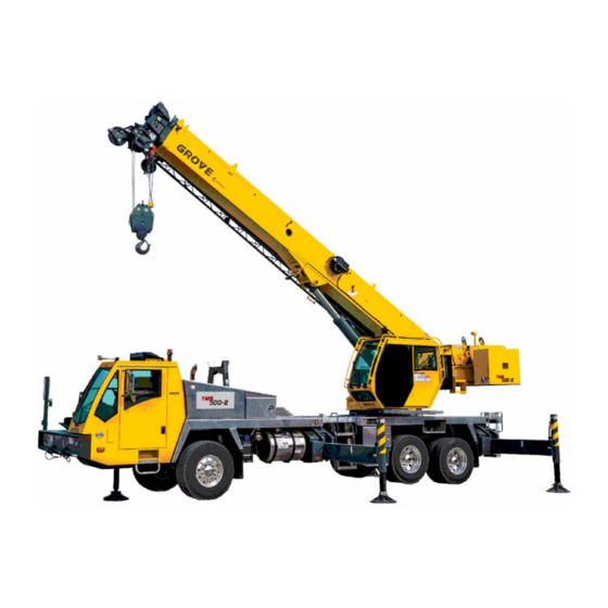
Manitowoc Grove TMS500-2 Operator's Manual (298 pages)
Brand:
Manitowoc
| Category:
Construction Equipment
| Size: 16.37 MB
Table of Contents
Table of Contents
8
Safety Messages
24
General
24
Safety Alert Symbol
24
Signal Words
24
Safety Decals
24
Accidents
24
Operator Information
25
Operator Qualifications
25
Operational Aids
26
Rated Capacity Limiter (RCL) Systems
26
Anti-Two-Blocking Device
27
Working Area Limiter (if Equipped)
27
Crane Stability/Structural Strength
28
Load Charts
29
Work Site
29
Wind Forces
29
Wind Speeds
30
Determination of 3-Second Wind Gust Speed at Boom Tip Height
32
Size and Shape of the Load
32
Determining Wind Drag Coefficient (CD)
33
Example and Sample Calculations (Non-Metric)
40
Lifting Operations
42
Multiple Crane Lifts
43
Lifting Multiple Loads
43
Tilt-Up Panel Lifting
43
Outrigger Lift off
44
Pile Driving and Extracting
44
Counterweight
44
Crane Equipment
45
Crane Inspection
45
Electrocution Hazard
45
Set-Up and Operation
46
Electrocution Hazard Devices
47
Electrical Contact
47
Special Operating Conditions and Equipment
48
Grounding the Crane
48
Personnel Handling
49
Environmental Protection
50
Maintenance
50
Service and Repairs
50
Hydraulic Fluid
50
Moving Parts
51
Before Maintenance or Repairs
51
After Maintenance or Repairs
51
Lubrication
51
Tires
51
Hoist Rope
52
Synthetic Hoist Rope
52
Wire Rope
52
Sheaves
53
Batteries
54
Super Capacitor (if Equipped)
54
General Maintenance
54
Transporting the Crane
54
Travel Operation
55
Work Practices
56
Personal Considerations
56
Crane Access
56
Job Preparation
56
Working
57
Lifting
57
Hand Signals
58
Boom Extension
60
Parking and Securing
60
Shut-Down
60
Cold Weather Operation
60
Temperature Effects on Hook Blocks
61
Temperature Effects on Hydraulic Cylinders
61
Model Specific Information
63
Overload Inspection
63
Boom Inspection
64
Superstructure Inspection
66
Carrier Inspection
68
Carrier Cab Controls and Indicators
74
Transmission Shift Lever
75
Spare Switch/Indicator
75
USB Ports
75
Volt Outlet
75
Fire Extinguisher
75
Horn Button
75
Turn Signal/Headlight High Beam Low Beam Lever
75
Brake Pedal
75
Cab Circulating Fan
75
Windshield Wiper and Washer
75
Steering Wheel Controls
76
Flash Marker Lights Switch
76
Windshield Washer/Wiper/Speeds
76
Horn Switch
76
Cruise Control ON/OFF Switch
76
Cancel Set Speed Switch
76
Set Speed/Coast Switch
76
Resume Set Speed/Accelerate Switch
76
Flash Headlights Switch
76
Headlights Switch
78
Dimmer Switch
78
Beacon Light Switch (Optional)
78
Engine Brake ON/OFF Switch
78
Engine Brake High/Low Switch
78
Exhaust System Cleaning Initiate Switch
79
Engine Speed Increment/Decrement Switch
79
Remote Control ON/OFF Switch (Optional)
79
Remote Control Indicator (Optional)
79
Anti-Lock Braking System/Automatic Traction Control (ABS/ATC) Switch
79
Hill Start Aid (HSA) System
79
Hill Start Aid (HSA) Indicator
79
Inter-Axle Differential Lock Switch
79
Cross-Axle Lock Switch (Optional)
79
Suspension Inflation Switch
79
Tire Inflation Switch
80
Heater/Air Conditioner Fan Speed Switch
80
Heater/Air Conditioner Temperature Control Switch
80
Heater/Air Conditioner Select Switch
80
Ignition Switch
80
Parking Brake Control
80
Dual Air Pressure Gauge
80
Control Panel Indicator and Gauge Display
81
Cross-Axle Lock Indicator (Optional)
82
Inter-Axle Lock Indicator
82
Suspension Deflated Indicator
82
ABS Traction Control Indicator
82
Tire Inflation Indicator
82
Left Turn Signal Indicator
82
Marker Lights on Indicator
82
High Beam Indicator
82
Parking Brake Engaged Indicator
82
Battery Charge Indicator
82
Anti-Lock Braking System (ABS) Indicator
83
Check Transmission Indicator
83
Malfunction Indicator Lamp
83
Low Oil Pressure Indicator
83
Engine Stop Indicator
83
Engine Warning Indicator
83
OK Button
83
Menu Button
83
Fuel Gauge
83
Speedometer
83
High Exhaust System Temperature Indicator
84
Engine Coolant High Temperature Indicator
84
Cruise Control Indicator
84
Engine Coolant Temperature Gauge
84
Down Button
84
Up Button
84
Tachometer
84
Exhaust System Cleaning Indicator
84
Wait to Start Indicator
85
Lcd
85
Seat Belt Unfastened Indicator
86
Outrigger Controls and Indicators
87
Outrigger Control Panel
87
Outrigger Beam Selector Switches
87
Extend Switch
88
Center Front Jack Switch
88
Jack Selector Switches
88
Emergency Stop Switch
88
Retract Switch
88
Power Indicator Light
88
Auto Level Switch
88
Bubble Level Indicator (Not Shown)
88
Outrigger Operation Indicator Lights
88
Superstructure Cab
89
Foot Pedals
89
Turntable Swing Lock Pin Control Handle
89
Seat Joystick and Armrest Controls
89
ODM and RDM Panels
89
Superstructure Overhead Control Panels
89
Superstructure Cab Overhead Controls
90
Skylight Window Latch
90
Skylight Wiper and Wiper Controls
90
Skylight Sunscreen
91
Dome Light
91
Cab Circulating Fan
91
Right Side Window Latch
91
Emergency Stop Switch
91
Overhead Control Panels
91
Radio (Optional)
91
Diesel Fired Cab Heater Controls (Optional)
91
Work Lights Switch
91
Boom Lights Switch (Optional)
91
RCL External Light Tower (Optional)
92
Anemometer (Optional)
92
Removing the Anemometer Assembly
92
Installing the Anemometer Assembly
93
Changing the Anemometer Battery
93
Stowing the Anemometer Assembly for Travel
93
Stowing the Anemometer Assembly for
93
Superstructure Overhead Control Panel
94
Windshield Wiper Switch
94
Windshield Washer Switch
94
Skylight Wiper Switch
94
Heater/Air Conditioner Fan Speed Switch
94
Heater/Air Conditioner Temperature Control Switch
94
Heater/Air Conditioner Switch (Standard)
94
Fresh Air/Recirculation Air Switch
94
Engine Speed Increment/Decrement Switch
94
Heater/Air Conditioner Temperature Control
94
Wait-To-Start Indicator
95
Crane Function Enable/Disable Switch
95
Hoist Bypass Switch
95
Boom up Bypass Switch
95
Limits Bypass Switch
95
Foot Pedal Controls
95
Foot Throttle Pedal
95
Telescope Control Foot Pedal (Optional)
95
Swing Brake Pedal
96
360° Swing Lock Pedal (Optional)
96
360° Swing Lock Release Lever (Optional)
96
Control Seat Assembly
97
Right Hand Arm Rest Controls
97
Left Hand Arm Rest Controls
97
Horn Button
97
Free Swing Button
97
Deadman Switches (Dual Axis - Controllers Only)
97
Deadman Switches
97
Only)
97
Seat Slide Lever
98
Seat Frame Slide Lever
98
Seat Height Adjustment Lever
98
Seat Back Adjustment Lever
98
Seat Switch (Not Shown)
98
Air Conditioner/Heater Climate Unit
98
Left Hand Arm Rest Controls
98
Swing/Telescope or Swing/Auxiliary Hoist Control Lever (Dual Axis)
99
Hoist High Speed Toggle Switch
99
Auxiliary Hoist Rotation Indicator (Optional)
99
Outrigger Extend/Retract Switch
99
Swing Enable/Disable Switch
99
Boom Telescope Enable/Disable Switch
99
Auxiliary Hoist Enable/Disable Switch (Optional)
99
Auxiliary Hoist Enable/Disable Switch
99
(Optional)
99
RCL Bypass Switch
100
Right Hand Arm Rest Controls
100
Boom Lift/Main Hoist Control Lever (Dual Axis)
101
Hoist High Speed Toggle Switch
101
Hoist Rotation Indicator
101
Jog Dial
101
Boom Lift Function Enable/Disable Switch
101
Main Hoist Enable/Disable Switch
101
Main Hoist Controller (Single Axis Option)
102
Boom Lift Controller (Single Axis Option)
102
Boom Telescope or Auxiliary Hoist Controller (Single Axis Option)
102
Swing Controller (Single Axis Option)
103
Operator Display Module and Rated Capacity Limiter Display Module
103
Rated Capacity Limiter Display Module (RDM)
103
Operator Display Module (ODM)
103
Navigation Control Pad
103
USB Connector
104
RCL Shutdown Warning Indicator
104
RCL Early Warning Indicator
104
Anti- Two-Block Indicator
104
Minimum Wrap Limiter System Indicator (Optional)
105
Swing Brake Engaged Indicator
105
Brightness Sensor
105
Internal Temperature Warning Indicator
105
Switching Displays
105
Ignition Switch
106
Turntable Swing Lock Pin Control Handle
106
Operator Display Module (ODM) - Main Screen
106
Alert Icons
109
Status Bar Icons
112
Operating Elements of the Crane Control System (CCS)
114
Crane Directional Information
114
General Rules for Buttons and Symbols on the CCS Display
115
Crane Control System (CCS) - Overview
115
Exiting the Menu/Input Mode
116
Enter the Values with Jog Dial
116
Enter Values on the Crane Control System (CCS) Panel
116
Input Confirmation
117
CCS Display and Menus
117
Menu Groups
117
Warning Message/Error Message Display Area
119
Camera Group (Optional)
119
Crane Function Menu Group
119
Outrigger Function
119
Working Range Limiter (WRL) Group Menu
119
Introduction
119
WRL - Swing Angle Limitation Function
119
WRL - Boom Angle Limitation Function
119
WRL - Boom Height Limitation Function
120
WRL - Working Radius Limitation Function
120
WRL - Virtual Walls Limitation Function
120
Errors (Fault Code) Group Menu
120
Crane Operation Error Function
120
Engine Error Function
120
Information Group Menu
120
Operating Hours Function Icon
120
Software Version Icon
120
Legal Notice Icon
120
Tools User Settings Group Menu
121
Time Zone Function
121
Display Screen Brightness Function
121
Unit of Measure Function
121
Remote Drive (Optional)
121
Carrier Cab Controls and Indicators
121
Superstructure Remote Drive Controls
122
Left Arm Rest
122
Service Brake Pedal
123
Operation
123
Enable the Remote Drive Option
123
Disable the Remote Drive Option
123
Truck Steering Operation
124
Pedal Operation
124
Suspension
124
Troubleshooting
124
Remote Control (Optional)
125
Indicators
125
Remote Control Icon
125
Remote Control Operation
125
Remote Control System Components
125
Remote Control Components
128
Display Components
129
Preparing for Remote Control Operation
130
Operating Remote Control
131
Engine Start/Stop/Throttle
133
Outrigger Beams
135
Outrigger Jacks
137
Hoist Control (Main and Aux)
139
Pre-Starting Checks
144
Fuel Supply
144
Fuel System Description
144
Fuel Tank
144
Fuel Filter-Water Separator
144
Diesel Exhaust Fluid (DEF) Supply
144
Engine Oil
144
Engine Coolant
144
Batteries
144
Hydraulic Reservoir and Filter
144
Seat Belt
145
Seat Belt Maintenance
145
Cleaning Seat Belt Webbing
145
Signal and Running Lights
145
Service and Parking Brakes
145
Anti-Lock Braking System (ABS)
145
ABS Power-Up Sequence
145
ABS Switch Operation
146
Tires
146
Wheels
146
Accessories
146
Daily Lubrication
146
Air Cleaner
146
Preload Check
146
Using Your Load Chart
146
Engine Operation
149
Start-Up Procedure
149
Idling Engine
150
Engine High Idle
150
Racing Engine
150
Exhaust System Cleaning
150
When to Manually Clean the Exhaust System
150
Initiating the Manual Exhaust Cleaning Process
151
Inhibiting the Exhaust System Cleaning
151
Shutdown Procedure
151
Battery Disconnect
151
Cold Weather Operation
151
Auxiliary Cab Heater (Optional)
152
Diesel Fuel
152
Crane Warm-Up Procedures
152
Engine
153
Hydraulic Oil System
153
Hoist
153
Swing Drive and Turntable Bearing
153
Axles
153
Driving the Crane
154
Seat Belts
154
Traveling - General
154
Securing the Superstructure for Travel
155
Securing the Carrier for Travel
155
Tie-Down Procedure for Hook Block
155
Traveling - Towing/Pulling
156
Traveling - Being Towed/Pulled
156
Traveling on Slopes
157
General Conditions
157
Slope Limitations - Fore/Aft Travel
158
Slope Limitations - Side Slope Travel
158
Traveling with Boom Extension Erected
158
Automated Transmission
158
Gear Display
159
Start-Up
159
Power down
160
Reverse Mode
160
Drive Mode
160
MANUAL Mode
160
MANUAL / Hold Mode
161
LOW Mode
161
Hill Start Aid (HSA) System
161
Differential Control Switches
162
Operating the Differential Locks
162
Brakes
162
Anti-Lock Brake System (ABS)
163
ABS Power-Up Sequence
163
ABS Switch Operation
163
Automatic Traction Control (ATC) Functional Overview
164
ATC Operation
164
System Operation
164
Component Function
164
Traction Control Power-Up Sequence
164
Traction Control Switch Operation
164
Thermal (Brake Heat) Protection
165
ABS/ATC Partial Shutdown
165
Engine Brake
165
Recommended Crane Shutdown Procedures
165
Superstructure Cab Platform
165
Craning Functions
166
Controller Operation
166
Proper Crane Leveling
166
Bubble Level Indicator Adjustment
166
Using the Outriggers
166
Setting the Outriggers from the Superstructure Cab
167
Setting the Outriggers from the Outrigger Control Panels
167
Setting the Outriggers from the Superstructure
167
Outrigger Control Panel
168
Outrigger Monitoring System (OMS)
169
Engaging the Outrigger MID-Extend Lock Pin
169
Stowing the Outriggers from the Superstructure Cab
169
Stowing the Outriggers from the Superstructure
169
Stowing the Outriggers Using the Carrier Outrigger Control Panels
170
Stowing the Outrigger MID-Extend Lock Pin
170
Swinging the Superstructure
170
Dual Axis Controllers
171
Single Axis Controller (Optional)
171
Elevating and Lowering the Boom
171
Elevating the Boom
171
Dual Axis Controllers
172
Single Axis Controller (Optional)
172
Lowering the Boom
172
Telescoping the Boom
173
Extending the Boom
173
Dual Axis Controller
173
Single Axis Controller (Optional)
173
Foot Pedal
173
Selecting the Hoist Speed Range
173
Retracting the Boom
174
Dual Axis Controller
174
Single Axis Controller (Optional)
174
Foot Pedal
174
Lowering and Raising the Main Hoist Rope
174
Lowering the Main Hoist Rope
175
Minimum Wrap Limiter System (Optional)
175
Raising the Main Hoist Rope
175
Lowering and Raising the Auxiliary Hoist Rope (Optional)
175
Lowering the Auxiliary Hoist Rope
176
Minimum Wrap Limiter System (Optional)
176
Raising the Auxiliary Hoist Rope
176
Stowing and Parking
176
Leaving Crane Unattended
177
Navigating the Operator Display Module (ODM) and Rated Capacity Limiter (RCL) Display Module
177
Tms500-2 Operator's Manual
177
Module
177
Using the Operator Display Module (ODM)
178
Main (Home) Screen
179
Active Screen Indicator Area
179
Menu Screen Layout
180
Menu Screen
182
Camera Group Menu
182
Crane Function Group Menu
182
Outrigger Group Functions
182
Accessing the Outrigger Group Function Screen
183
Accessing the Outrigger Group Function
183
Extending/Retracting the Outrigger Jacks
184
Screen
184
Extending/Retracting the Outrigger Jacks - Individually
185
Individually
185
Extending/Retracting the Center Front Jack
187
Exiting the Outrigger Extend/Retract Function Screen
187
Working Range Limiter (WRL) Menu Group
188
Introduction
188
WRL Limitations Overview
189
Accessing a WRL Limitation Screen
191
WRL - Swing Angle Limitation Menu
196
Setting the Swing Angle Limitation
196
The Swing Angle Limitation Menu
197
Setting Swing Angle Limitation by Crane Position
197
Setting Swing Angle Limitation by Value
197
Swing Angle Limitation with Lock-Out Function Enabled
198
WRL - Boom Angle Limitation Menu
198
Setting the Boom Angle Limitation Menu
199
Setting the Boom up Angle Limitation by Crane Position
199
Setting the Boom down Limitation by Crane Position
199
Position
199
Setting Boom up Limitation by Value
200
Setting Boom down Limits Menu by Value
200
WRL - Boom Height Limitation Menu
201
Setting the Boom Height Limitation
201
Setting Boom Height Limitation Using Crane Position
201
Position
201
Setting Boom Height Limitation by Value
202
WRL - Working Radius Limitation
203
WRL - Working Radius Limit Menu
204
Setting Inner/Outer Working Radius Limitation by Crane Position
204
Setting Inner/Outer Working Radius Limitation by Value
204
Working Radius Limitation Disable Procedure
205
WRL - Virtual Walls Limitation Menu
206
Defining Subsequent Virtual Walls
208
Errors (Fault Code) Group Menu
210
Crane Operation Function
210
Engine Fault Function
210
Information Group Menu
210
Accessing an Information Group Function Screen
211
Exiting an Information Group Function Screen
211
Viewing the Operating Hours
211
Viewing the Software Version Screen
213
Viewing the Legal Notice Screen
213
Tools Group Menu
214
Accessing a Tools Group Function Screen
214
Exiting a Tools Group Function Screen
214
Setting the Controller Sensitivity Function
214
Setting the Controller Speed Function
216
Setting the Wiper Interval Function
218
Setting the Economy (ECO) Mode Function
219
ECO Terminology
219
ECO Requirements
219
Operating Procedures
219
ECO Operation
220
ECO Benefits
220
Exhaust System Cleaning Function
220
Tools User Settings Group Menu
220
Setting the Time Zone Function
221
Setting the Display Screen Brightness Function
221
Setting the Units of Measure Function
222
Using the Rated Capacity Limiter Display Module (RDM)
222
Rated Capacity Limiter (RCL) Group - Menu
222
Rated Capacity Limiter (RCL) Configuration Screen
222
Using the Rated Capacity Limiter Display Module
222
RCL Configuration Screen
223
Entering a Load Chart Code Number Manually
224
Data Logger
224
Legal Notice Screen
225
Rated Capacity Limiter (RCL) Main Screen
226
Overriding the Outrigger Monitoring System
227
Limits Bypass Indicators
227
Load Chart and Miscellaneous Indicators
227
General
229
Environmental Protection
229
Cummins Oil Registration List
229
Standard Lubricants
231
Arctic Lubricants and Conditions
233
Temperatures below -9°C (15°F)
233
Cold Weather Lubricants
233
Cylinder Rod Surface Protection
235
Wire Rope Lubrication
235
Lubrication Points
235
Drivetrain Lubrication
237
Steering Lubrication
241
Axle Lubrication
242
Outrigger Lubrication
246
Miscellaneous Lubrication
247
Turntable & Cab Platform Lubrication
248
Hoist Lubrication
250
Turntable Central Lubrication
251
Boom Lubrication
253
Monthly Lubrication Work
258
Carwell® Rust Inhibitor
259
Protecting Cranes from Corrosion
259
Cleaning Procedures
259
Inspection and Repair
260
Application
260
Areas of Application
260
Hoist Platform
266
Installing Cable on the Hoist
266
Anti- Two-Block (A2B) Switch
266
Locking A2B Switch
267
Unlocking A2B Switch
267
Before Operation Check
267
Cranes with Main Hoist Only
267
Cranes with Main and Auxiliary Hoists
267
Hoist Rope Reeving
269
Advertisement
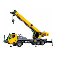
Manitowoc Grove TMS500-2 Service Manual (361 pages)
Brand:
Manitowoc
| Category:
Construction Equipment
| Size: 20.93 MB
Table of Contents
This Page Blank
5
Table of Contents
5
Section 1 1
13
Using the Service Manual
13
Safety Messages
14
Axles
15
Brakes
15
Capacities
15
Dimensions
15
Engine
15
General
15
List of Specifications
15
Suspension
15
Transmission
15
Wheels and Tires
15
Boom 102
16
Cable
16
Hoists
16
Hydraulic Pumps
16
Swivel Assembly
16
Cleanliness
23
Disassembly and Assembly
23
General Maintenance
23
Locks
23
Pressing Parts
23
Removal and Installation
23
Batteries
24
Bearings
24
Gaskets
24
Wires and Cables
24
Fatigue of Welded Structures
25
Hydraulic Systems
25
Loctite® Thread Locking Compound
25
Fasteners and Torque Values
26
Hoist Cable Inspection and Maintenance
33
Weld Studs
33
Wire Rope
34
Wire Rope Inspection (Running Ropes and pendant Cables)
35
Retraction Cables)
36
Seizing Wire Rope
36
Wire Rope Inspection
36
Wire Rope Inspection (Boom Extension and Retraction Cables)
36
Wire Rope Inspection (Running Ropes and pendant Cables)
36
Wire Rope Replacement (All Wire Rope)
36
Installing 35X7Class Wire Rope
37
Procedures for Cutting and Preparing 35X7 Class Wire Rope
38
Section 2 Hydraulic System 2
39
Description
39
Section 2
39
Draining and Flushing
41
Maintenance
41
Removing Air from the Hydraulic System
42
Description
43
Hydraulic Reservoir and Filter
43
Parts Replacement
43
Supply Pressure and Return Circuit
43
Pump Distribution
44
Maintenance
46
Troubleshooting
46
Element Installation
47
Element Removal
47
Environmental Protection
47
Return Hydraulic Filter Assembly
47
Description
49
Hydraulic Pumps
49
Maintenance
49
Carrier Valves
55
General
55
Description
57
Maintenance
57
Outrigger Selector Manifold Valve
57
Description
59
Maintenance
59
Outrigger Control Manifold
59
Description
64
Internal Leak Testing
64
Pilot Operated Check Valve
64
Maintenance
65
Superstructure Hydraulic Valves
66
Main Directional Valve Assembly
67
Accessory Manifold Assembly
68
Checking for Leaks
69
Cylinders
69
General
69
Maintenance
69
Superstructure Hydraulic System
69
Equipment
71
Objective
71
Pressure Setting Procedures
71
Valve Pressure Setting Table
71
Service Tool Notes
72
Procedure for Checking/Setting the Piston Pump Cut-Off and Differential Pressures
74
Procedure for Checking/Setting the Pilot Supply Pressure
75
Procedure for Checking/Setting the Main Directional Control Valve, Load Sense, Lift and Telescope Pressures
76
Procedure for Checking/Setting Swing Pressure
78
Procedure for Checking/Setting the Swing
78
Procedure for Checking/Setting the Swing Brake Release Pressure
78
Procedure for Checking/Setting Outrigger Pressure
79
Procedure for Checking Air Conditioning Operation
81
Procedure for Checking/Setting the Center Front Stabilizer Pressure
82
Procedure for Checking/Setting the Front Steer Pressure
82
Procedure for Adjusting Electronic Controllers (Meter-In Dead Band And/Or Max Function Speeds)
84
Section 3 Electrical System
87
Batteries
87
Carrier Cab
87
Description
87
Section 3
87
Batteries
88
Carrier Cab
88
Carrier Power Panel and Fuse Panels
88
Carrier Cab Fuse and Relay Panels
90
Anti-Lock Brake System (ABS)
91
Superstructure Cab Fuse and Relay Panels
93
Camera System (Optional)
95
General
95
Maintenance
95
Radios (Optional)
95
General Troubleshooting
96
Tools for Troubleshooting
96
Troubleshooting Engine Starting Problems
96
Charging the Batteries
97
Connector Troubleshooting
97
Jump Starting Hazard
97
Troubleshooting
97
Troubleshooting Battery Charging Problems
97
Troubleshooting Slip Ring-Caused Electrical Problems
97
DI-Electrical Grease Application
98
Troubleshooting Lights
99
Alternator Replacement
100
Troubleshooting Accessories
100
Troubleshooting Alarms, Indicators, and Emergency Components
100
Troubleshooting Gauges and Meters
100
Starter Replacement
101
Battery Replacement
103
Instrument Replacement
104
Relay Panel Component Replacement
104
All Other Switches
105
Rocker Switch
105
Switch Replacement
105
Windshield Wiper Assembly Replacement
106
Carrier Cab
108
Skylight Wiper Assembly Replacement
109
Superstructure Wiper Assembly
109
Windshield Washer Assembly Replacement
109
Windshield Wiper Assembly Replacement - Superstructure Cab
110
Windshield Washer Assembly Replacement
113
Computer Modules
114
Fault Codes
114
Remote Controller (Optional)
114
Troubleshooting the Crane Control System (CCS)
114
Using the Operator Display Module (ODM)
114
Battery Charger
117
Receiver
117
Remote Controller Battery
117
Tms500-2 Service Manual Boom Section 4 Boom
119
Boom Extension Sequence
120
Boom System Components
120
Extend Synchronizing Cable
120
Fly Retraction Cables
120
Fly Section Extension Cables
120
Outer MID Retract Cables
120
Telescope Cylinder
120
Telescope Circuit
122
Telescope Circuit Troubleshooting
123
Description
124
Lift Circuit
124
Lift Circuit Troubleshooting
125
Theory of Operation
125
General Maintenance Notes
126
Boom Extension Removal (Optional)
127
Boom Removal
128
Remove the Base Section
131
Disconnect the Inner MID Section
132
Remove the Inner MID Section
133
Remove the Outer MID Section
135
Remove the Telescope Cylinder
137
Boom Nose Sheaves
138
Boom Nose Sheave Removal
139
Boom Assembly Procedure
141
Install Telescope Cylinder
141
Install the Outer MID Section
144
Install the Inner MID Section
148
Tensioning the Boom Extend and Retract Cables
153
Install the Base Section
156
Final Boom Installation
158
Swingaway Extension Installation (Optional)
159
Boom Inspection
161
Boom Maintenance
161
Functional Test of the Boom
161
Boom Alignment and Servicing
162
Extension and Retraction Cable Maintenance
162
Inspection
163
Lift Cylinder Installation
164
Lift Cylinder Maintenance
164
Lift Cylinder Removal
164
Section 5 Hoist and Counterweight
167
Maintenance
168
Removal
168
Warm-Up Procedure
168
Functional Check
169
Installation
169
Servicing
169
Hoist Maintenance and Inspection
170
Usage and Inspection
170
Brake Test Procedure
172
Hoist to Boom Alignment
173
Preparation
173
Procedure
173
Tools Required
173
Description
174
Maintenance
174
Piston Motor and Control Valve
174
Description
175
Idler Drum and Cable Follower
175
Maintenance
175
Description
177
Hoist Drum Rotation Indicator System
177
Maintenance
177
Troubleshooting
177
Counterweight Removal
179
Counterweights
179
Section 6 Swing Section
183
Description
188
Maintenance
188
Swing Motor
188
Description
189
Maintenance
189
Swing Gearbox and Brake
189
Description
190
Maintenance
190
Maintenance of Gearbox
190
Swing Bearing
190
Description
196
Swivels
196
Hydraulic Swivel
198
Electrical Slip Ring Assembly
200
Section 7 Power Train
203
Engine Removal
204
Engine Installation
207
Description
208
Engine Control System
208
Engine Drive Belts
208
Functional Operation
208
Engine Control System Switches and Indicator Lights
209
Description
211
Fuel System
211
Maintenance
212
Air Intake System
213
Description
213
Maintenance
213
Description
217
Exhaust System
217
Exhaust System Removal
217
Slip Joint Exhaust Connectors
217
System Installation
217
Exhaust System
218
After-Treatment Diesel Exhaust Fluid (DEF)
219
DEF Tank
219
DEF Dosing Unit Filter
220
Description
222
Maintenance
222
Water Cooling System
222
Cleaning
224
Component Inspection
225
Radiator Assembly Removal and Installation
226
Description
228
Drive Lines
228
Drive Train
228
Maintenance
228
ECA Removal and Assembly Instructions
230
Electronic Clutch Actuator (ECA)
230
Installation Instructions
230
Removing Transmission from Engine
230
Transmission
230
Mounting Transmission to Engine
231
Pump/Pto Assembly
232
Pump/Pto Replacement
232
Section 8 Undercarriage
235
Anti-Lock Brake System (ABS)
235
Front Axle
236
Maintenance
236
Rear Axles
241
Description
246
Vehicle Maintenance Schedule
246
Wheels and Tires
246
Description
247
Maintenance
247
Steering System
247
Description
250
Maintenance
250
Steering Gearbox
250
Air System
251
Description
251
Theory of Operation
251
Maintenance
254
Air System Components
256
Brakes
266
Description
266
Air Supply
267
Anti-Lock Braking Systems (ABS)
267
Automatic Traction Control
267
Emergency Braking
267
Non-Asbestos Warning
267
Normal Braking
267
Vehicle Parking
267
Description
268
Front Brakes
268
Maintenance
268
Automatic Slack Adjuster
274
Description
274
Maintenance of Slack Adjuster
274
Description
277
Rear Brakes
277
Maintenance
278
Rear Brake Assembly
282
ABS System Description
285
ATC System Description
287
ABS Troubleshooting
289
Troubleshooting Diagnostic Trouble Codes: Traction Control Valves
297
Power Supply Tests
299
Troubleshooting Diagnostic Trouble Codes: J1939 Serial Communications
299
Miscellaneous Troubleshooting
301
Troubleshooting Wiring
302
Special Tools
305
Tests, Repair and Adjustment
305
Component Removal and Installation
307
Description
309
Outriggers
309
Theory of Operation
309
Maintenance
310
Description
317
Extension Cylinder
317
Maintenance for Extension Cylinder
317
Maintenance for Jack Cylinders
317
Outrigger Jack Cylinders
317
Center Front Jack Cylinder
318
Description
318
Maintenance for Center Front Jack Cylinder
318
Functional Check of Center Front Jack Cylinder
319
Description
321
OMS Linear Position Sensors
321
Outrigger Monitoring System
321
Advertisement
Related Products
Manitowoc Grove TMS9000-2 Series
Manitowoc Grove TMS800E
Manitowoc Grove TMS800E13
Manitowoc Grove TMS700E
Manitowoc Grove RT9150E
Manitowoc Grove RT890E
Manitowoc Grove RT9130E
Manitowoc Grove GMK4070E
Manitowoc Grove GMK6300L
Manitowoc GROVE RT650E
Manitowoc Categories
Construction Equipment
Ice Maker
Accessories
Commercial Food Equipment
Dispenser
More Manitowoc Manuals
Login
Sign In
OR
Sign in with Facebook
Sign in with Google
Upload manual
Upload from disk
Upload from URL