Table of Contents
Advertisement
Available languages
Available languages
Quick Links
16" Digital Angle Finder
MODEL HLLT16
ATTACH YOUR RECEIPT HERE
Serial Number ______________________ Purchase Date _______________________
Questions, problems, missing parts? Before returning to your retailer,
call our customer service department at 1-877-888-1880, 8:30 a.m. – 8:00
p.m. EST (Monday – Friday) & 10:00 a.m. – 6:00 p.m. EST (Saturday and
Sunday).
Advertisement
Chapters
Table of Contents

Subscribe to Our Youtube Channel
Related Manuals for Hammerhead HLLT16


Summary of Contents for Hammerhead HLLT16
- Page 1 16" Digital Angle Finder MODEL HLLT16 ATTACH YOUR RECEIPT HERE Serial Number ______________________ Purchase Date _______________________ Questions, problems, missing parts? Before returning to your retailer, call our customer service department at 1-877-888-1880, 8:30 a.m. – 8:00 p.m. EST (Monday – Friday) & 10:00 a.m. – 6:00 p.m. EST (Saturday and...
-
Page 2: Table Of Contents
Warranty ............19 TECHNICAL SPECIFICATIONS COMPONENT SPECIFICATIONS Model HLLT16 2 x 1.5V AA battery Power supply Recommended Use Indoors or Outdoors Angle measuring range 0°... -
Page 3: Safety Instructions
• Always dispose of used batteries according to your local ordinance; do not incinerate the batteries. • Use only those accessories that are recommended by HAMMERHEAD for use with this product. Use of accessories that have been designed for use with other tools could result in serious injury. - Page 4 SAFETY INSTRUCTIONS NOTICE: This equipment has been tested and found to comply with the limits for a Class B digital device, pursuant to Part 15 of the FCC Rules. These limits are designed to provide reasonable protection against harmful interference in a residential installation.
-
Page 5: Unpacking
UNPACKING When unpacking the box, do not discard any packing materials until all of the contents are accounted for: a. Open the carton to locate the following: • Digital Angle Finder • 2 pcs. 1.5V AA battery • Soft bag •... -
Page 6: Description
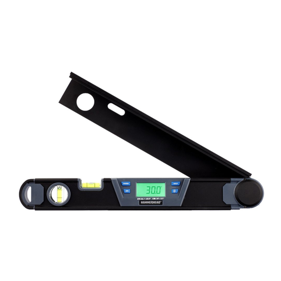
DESCRIPTION KNOW YOUR DIGITAL ANGLE FINDER (Fig. 1) The 16” Digital Angle Finder is a precision tool for measuring and transferring angles. Use it as: • an angle finder • a compound-cut calculator • a protractor • a level 16" DIGITAL ANGLE FINDER... - Page 7 DESCRIPTION PARTS DESCRIPTION Folding leg Window for horizontal bubble level Window for vertical bubble level Joint cover Base leg SPR Button: stores the spring angle as a fixed value SPR/CNR/MTR/BVL Button: for calculating the miter and bevel angle (identified as “MTR/BVL button” in this manual) POWER button: turns the Digital Angle Finder on or off;...
- Page 8 DESCRIPTION GLOSSARY SPR: Spring Angle (the angle between the wall and the flat, back side of crown molding) CNR: Corner (the angle between the two adjacent walls) MTR: The miter angle computed for the miter saw BVL : The bevel angle computed for the miter saw 16"...
-
Page 9: Operation
OPERATION 1. BATTERY INSTALLATION (Fig. 2) This Digital Angle Finder uses two “AA” batteries. a. Open the battery cover, located in the back of the tool (Fig. 2). b. Insert two new “AA” alkaline batteries with the polarity (+/-) as indicated on the inside of the battery compartment. - Page 10 OPERATION 2. TURN THE DIGITAL ANGLE FINDER ON, OFF, AND REVERSE THE IMAGE a. Press the ON/OFF button to turn on the Digital Angle Finder. The LCD screen will first briefly display all of the angle-calculation elements and then display the relative angle between the folding leg and the base leg. b.
- Page 11 OPERATION 4. MEASURING ANGLES (Fig. 3) a. Press the ON/OFF button to turn on the tool. b. Unfold the folding leg from the α base leg (level body). c. Place each of the two legs flat against one of the surfaces forming the angle.
- Page 12 OPERATION 5. USING THE LEG EXTENSION (Fig. 4) The leg extension assists angle measurement when the geometry of the surfaces that form the angle are such β that the folding leg cannot contact one of α the surfaces. a. Attach the leg extension: Slide the leg extension from the end onto the folding leg.
- Page 13 OPERATION 6. DETERMINING THE MITER AND BEVEL ANGLES FOR CUTTING CROWN MOLDING The Digital Angle Finder can automatically calculate the exact miter-angle and bevel-angle cut settings for precise crown molding cuts, based on “SPR” and “CNR” information. Determine, save, and enter the spring angle (SPR) a.
- Page 14 OPERATION e. Press the “SPR” button to save the SPR angle in the tool for later use. “S” shown in the LCD display indicates that the spring angle is saved successfully (Fig. 8). NOTE: • To recall the saved spring angle, press the SPR button after the tool is turned on.
- Page 15 OPERATION Determine the corner angle( CNR) a. After determining or saving the SPR angle, place one leg of unit against each of two adjacent walls to measure the angle of the wall corner (Fig. 10); “CNR” will blink on the LCD display. b.
- Page 16 OPERATION Determine the miter and bevel angles for cutting crown molding a. Press the MTR/BVL button to display the miter angle; “MTR” will show in the LCD display (Fig. 12). b. Press the MTR/BVL button again to display the bevel angle; “BVL” will show on LCD display (Fig.
-
Page 17: Maintenance
MAINTENANCE This Digital Angle Finder has been designed to be a low-maintenance tool. However, in order to maintain its performance, you must always follow these simple directions. • Avoid exposing the tool to shock, continuous vibration or extreme hot or cold temperatures. -
Page 18: Troubleshooting
TROUBLESHOOTING PROBLEM CAUSE SOLUTION The LCD screen Batteries are installed Reinstall batteries with cannot be turned incorrectly. correct polarity. Battery voltage is low. Replace with new batteries when the empty battery icon appears on LCD. Inaccurate angle Dirt particles on the contact Clean the dirt particles. -
Page 19: Warranty
This digital angle finder is warranted to the original user to be free from defects in material and workmanship. If you believe that the tool is defective at any time during the specified warranty period, call HAMMERHEAD support at 1-877-888-1880 to speak with a customer service agent. This warranty does not cover: (1) Part failure due to normal wear or tool abuse (2) Any parts have been altered or modified by anyone other than authorized HAMMERHEAD personnel. - Page 20 16" DIGITAL ANGLE FINDER...
- Page 21 Detector de ángulos digital de 16'' MODELO HLLT16 ADJUNTE SU RECIBO AQUÍ Número de serie ____________________ Fecha de compra _____________________ ¿Preguntas, problemas, piezas faltantes? Antes de volver a la tienda, llame a nuestro Departamento de Servicio al Cliente al 1-877-888-1880, de 8:30 a.m.a 8:00 p.m.hora estándar del Este (lunes a viernes) y de...
-
Page 22: Especificaciones Técnicas
Garantía ............40 ESPECIFICACIONES TÉCNICAS COMPONENTE ESPECIFICACIONES Modelo HLLT16 Suministro de electricidad 2 baterías AA de 1,5 V Uso recomendado Para interiores/exteriores Rango de medición angular... -
Page 23: Instrucciones De Seguridad
• Deseche siempre las baterías usadas de acuerdo con las normas locales. No las queme. • Use solo aquellos accesorios que HAMMERHEAD recomienda usar con este producto. El uso de accesorios que se diseñaron para otras herramientas podría ocasionar lesiones graves. - Page 24 INSTRUCCIONES DE SEGURIDAD 2. Los cambios o las modificaciones que no estén aprobados explícitamente por la parte responsable del cumplimiento podrían invalidar la autoridad del usuario para utilizar el equipo. AVISO: Este equipo ha sido probado y ha resultado estar en conformidad con los límites para un dispositivo digital Clase B, conforme a la Sección 15 de las Normas de la FCC.
-
Page 25: Desembalaje
DESEMBALAJE Cuando desembale la caja, no descarte ningún material de embalaje hasta que todas las piezas estén contadas: a. Abra la caja e identifique lo siguiente: • Detector de ángulos digital • 2 baterías AA de 1,5 V • Bolsa suave •... -
Page 26: Descripción
DESCRIPCIÓN CONOZCA EL DETECTOR DE ÁNGULOS DIGITAL (Fig. 1) El detector de ángulos digital de 16'' es una herramienta de precisión para medir y transferir ángulos. Úselo como: • detector de ángulos • calculadora de corte compuesto • transportador • nivel DETECTOR DE ÁNGULOS DIGITAL DE 16''... - Page 27 DESCRIPCIÓN PIEZAS DESCRIPCIÓN Brazo plegable Ventana para nivel de burbuja horizontal Ventana para nivel de burbuja vertical Cubierta de junta Brazo base Botón SPR: se almacena el ángulo de inclinación como valor fijo. Botón SPR/CNR/MTR/BVL: para calcular el ángulo de inglete y de bisel (botón “MTR/BVL”...
- Page 28 DESCRIPCIÓN GLOSARIO SPR: ángulo de inclinación (el ángulo entre la pared y el lado posterior plano de la moldura de corona) CNR: esquina (el ángulo entre las dos paredes adyacentes) MTR: el ángulo de inglete que se calcula para la sierra ingletadora BVL : el ángulo de bisel que se calcula para la sierra ingletadora DETECTOR DE ÁNGULOS DIGITAL DE 16''...
-
Page 29: Operación
OPERACIÓN 1. INSTALACIÓN DE LAS BATERÍAS (Fig. 2) Este detector de ángulos digital utiliza dos baterías “AA”. a. Abra la tapa del compartimento para baterías, que se encuentra en la parte posterior de la herramienta (Fig. 2). b. Coloque dos baterías alcalinas “AA”... - Page 30 OPERACIÓN 2. CÓMO ENCENDER Y APAGAR EL DETECTOR DE ÁNGULOS DIGITAL E INVERTIR LA IMAGEN a. Presione el botón ON/OFF (Encendido/apagado) para encender el detector de ángulos digital. En la pantalla LCD, primero aparecerán rápidamente todos los elementos de cálculo de ángulo y, luego, se mostrará el ángulo relativo entre el brazo plegable y el brazo base.
- Page 31 OPERACIÓN 4. MEDICIÓN DE ÁNGULOS (Fig. 3) a. Presione el botón ON/OFF para encender la herramienta. b. Despliegue el brazo plegable α desde el brazo base (cuerpo de nivelación). c. Apoye cada brazo sobre una de las superficies que forman el ángulo.
- Page 32 OPERACIÓN 5. CÓMO USAR LA EXTENSIÓN DE BRAZO (Fig. 4) La extensión de brazo resulta útil para medir el ángulo cuando la superficie β de contacto es más corta que el brazo α plegable. a. Conecte la extensión de brazo: deslice la extensión de brazo sobre el brazo plegable desde el extremo.
- Page 33 OPERACIÓN 6. CÓMO DETERMINAR LOS ÁNGULOS DE INGLETE Y DE BISEL PARA COR- TAR LA MOLDURA DE CORONA El detector de ángulos digital puede calcular de manera automática los ajustes de corte de ángulo de inglete y de bisel exactos para cortar la moldura de corona de forma precisa, según la información de “SPR”...
- Page 34 OPERACIÓN d. Presione el botón “MTR/ BVL” (Inglete/Bisel): se calcula automáticamente el ángulo de inclinación y se lo muestra durante 3 segundos. También aparecerá “SPR” (Inclinación) en la pantalla (Fig. 7). e. Presione el botón “SPR” (Inclinación) para guardar el ángulo de inclinación en la herramienta y usarlo más adelante.
- Page 35 OPERACIÓN f. Presione el botón de encendido para encender la herramienta. g. Mueva el brazo plegable hasta que el ángulo de inclinación conocido aparezca en la pantalla LCD. Presione el botón MTR/ BVL para ingresar el ángulo SPR. Aparecerá “SPR” en la pantalla LCD (Fig. 9 y Fig. 7).
- Page 36 OPERACIÓN NOTA: En cualquier momento que encienda la unidad, presione el botón “SPR” para verificar el ángulo “SPR” guardado y luego pasará al modo “CNR” y “CNR” parpadeará en la pantalla “LCD” automáticamente, coloque la unidad en la ubicación de medida deseada como en el paso a.
- Page 37 OPERACIÓN b. Vuelva a presionar el botón MTR/ BVL para mostrar el ángulo de bisel. Aparecerá “BVL” (Bisel) en la pantalla LCD (Fig. 13). c. Registre los valores de MTR/BVL y configure los ángulos de inglete y de bisel en la sierra ingletadora compuesta.
-
Page 38: Mantenimiento
MANTENIMIENTO Este detector de ángulos digital se diseñó para ser una herramienta de bajo mantenimiento. Sin embargo, para mantener su rendimiento, siempre debe seguir estas instrucciones simples. • Evite exponer la herramienta a descargas eléctricas, vibración continua o temperaturas de frío o calor extremas. •... -
Page 39: Solución De Problemas
SOLUCIÓN DE PROBLEMAS PROBLEMA CAUSA SOLUCIÓN La pantalla LCD no Las baterías están instaladas Vuelva a colocar se enciende. de manera incorrecta. las baterías con la polaridad correcta. El voltaje de la batería es Coloque baterías bajo. nuevas cuando aparezca el icono de batería agotada en la pantalla LCD. -
Page 40: Garantía
Si cree que la herramienta tiene algún defecto en cualquier momento durante el período de garantía especificado, simplemente llame a Ayuda al cliente de HAMMERHEAD al 1-877-888-1880 para hablar con un agente de Servicio al Cliente. Esta garantía no cubre: (1) fallas en las piezas debido al desgaste natural o al uso indebido de la herramienta;...
Need help?
Do you have a question about the HLLT16 and is the answer not in the manual?
Questions and answers