Advertisement
Quick Links
COMPRESSOR MODEL
Portable Power
P.O.Box868 501-SanfordAve
Mocksville, N.C.27028
Revised (01-13)
OPERATING, MAINTENANCE,
PARTS MANUAL
HP60CMH
VHP90CMH
1
(
)
Doosan purchased Bobcat Company from Ingersoll-Rand Company in
2007. Any reference to Ingersoll-Rand Company or use of trademarks,
service marks, logos, or other proprietary identifying marks belonging
to Ingersoll-Rand Company in this manual is historical or nominative
in nature, and is not meant to suggest a current affiliation between
Ingersoll-Rand Company and Doosan Company or the products of
either.
Manual P/N 22189203 (01/17/2005)
Advertisement

Related Manuals for Ingersoll-Rand HP60CMH


Summary of Contents for Ingersoll-Rand HP60CMH
- Page 1 VHP90CMH Portable Power Doosan purchased Bobcat Company from Ingersoll-Rand Company in P.O.Box868 501-SanfordAve 2007. Any reference to Ingersoll-Rand Company or use of trademarks, Mocksville, N.C.27028 service marks, logos, or other proprietary identifying marks belonging Revised (01-13) to Ingersoll-Rand Company in this manual is historical or nominative...
- Page 2 QUALITY POLICY We will supply products and services that consistently meet the requirements of our customers and each other. Manual P/N 22189203 (01/17/2005)
-
Page 3: Table Of Contents
TABLE OF CONTENTS SECTION 1 …………………... SAFETY SECTION 2 …………………... WARRANTY/REGISTRATION SECTION 3 …………………... INSALLATION SECTION 4 …………………... GENERAL DATA SECTION 5 ……………………OPERATION SECTION 6 ……………………MAINTENANCE SECTION 7 ……………………LUBRICATION SECTION 8 ……………………TROUBLESHOOTING SECTION 9 ……………………PARTS ODERING SECTION 10 …………………. PARTS LIST Manual P/N 22189203 (01/17/2005) -
Page 4: Section 1
SECTION 1 – SAFETY SAFETY PRECAUTIONS If the discharged air is to be ultimately released into a confined space, adequate ventilation must be provided. General Information When using compressed air, always use appropriate Ensure that the operator reads and understands the personal protective equipment. - Page 5 A battery contains sulfuric acid and can give off gases, Ether is an extremely volatile, highly flammable gas. which are corrosive and potentially explosive. Avoid USE SPARINGLY! If too much is injected, it may result contact with skin, eyes and clothing. Incase of contact, in costly damage to the engine.
- Page 6 Manual P/N 22189203 (01/17/2005)
- Page 7 Manual P/N 22189203 (01/17/2005)
- Page 8 Manual P/N 22189203 (01/17/2005)
- Page 9 Manual P/N 22189203 (01/17/2005) Manual P/N 22189203 (01/17/2005)
- Page 10 Manual P/N 22189203 (01/17/2005) Manual P/N 22189203 (01/17/2005)
- Page 11 FREE SAFETY DECALS! To promote communication of Safety Warnings on products manufactured by the Portable Compressor Division in Mocksville, N.C., Safety Decals are available free of charge. The decal heading identifies safety decals: DANGER, WARNING or CAUTION. Decal part numbers are on the bottom of each decal and are also listed in the compressor’s parts manual.
- Page 12 3.5KW thru 7.0KW and 10KW – The earlier of twelve (12) months from shipment to or the accumulation of 2,000 hours of service by the initial user, whichever occurs first. Ingersoll-Rand will provide a new part or repaired part, at its election, in place of any part, which is found to be defective in material or workmanship during the period described above.
- Page 13 Spare Parts–Six (6) months from date of shipment. Ingersoll-Rand will provide a new part or repaired part, at its election, in place of any part, which is found upon its inspection to be defective in material and workmanship during the period prescribed above.
- Page 14 (IN GENERATORS AS OF 1/1/01) 2000 Deutz 2000 Available at dealer Ingersoll-Rand 4000 5 years/10,000 hours when using genuine Ingersoll-Rand fluids and parts. Refer to operator’s manual. Kubota (North America Only) 2000 Major components 36 months/3000 hrs parts only (Western Europe & Oceania)
- Page 15 Extended Limited Airend Warranty Ingersoll-Rand Portable Compressor Division is pleased to announce the availability of extended limited airend warranty. Announcement of the extended warranty coincides with the introduction of PRO•TEC™ Compressor Fluid. PRO•TEC™ Compressor Fluid is an amber colored fluid specially formulated for Portable Compressors and is being provided as the factory filled fluid for all machines except 1 XHP650/900/1070 models.
- Page 16 Machines shipped outside the United States require notification be made to initiate the machine warranty. Fill out the Warranty Registration Form in this section; keep a copy for your records and mail form to: Ingersoll-Rand Company Portable Compressor Division P.O. Box 868 Mocksville, North Carolina 27028 Attn: Warranty Department Note: Completion of this form validates the warranty.
- Page 17 The warranty and limitation of liability has been reviewed and understood by the owner/user. In the event that this unit is to be used within a nuclear facility, the owner/user shall notify Ingersoll-Rand of such use so that Ingersoll-Rand may arrange for appropriate nuclear liability protection from the owner licensee of the facility.
- Page 18 - - - - - - - - - - - - - - - - - - - - - - - - - - - - - - - - - - - - - - Manual P/N 22189203 (01/17/2005)
-
Page 19: Section 3
SECTION 3 – INSTALLATION INSTRUCTIONS Since the Ingersoll-Rand Compressor Module Series unit System Description – General is of the positive displacement type, an airflow control system must be provided to regulate the volume of air The Ingersoll-Rand compressor modules are semi-... - Page 20 PIPING General Ingersoll-Rand Compressor Module units will require customer provided piping from the compressor module to the hydraulic supply and the air service piping. These hoses are not provided with the units, as the required lengths of the hoses are dependent on the relative locations of modules in its installed location.
- Page 21 The 12-volt supply to the compressor must be no smaller that AWG size 10 wire. Larger wire should Ingersoll-Rand has available a remote oil cooler with be used if the total wiring length exceeds 12-feet. This is a12VDC electric fan that is sized for this application. This critical as the fan motor is sensitive to wiring voltage drop.
- Page 22 The motor in the compressor module unit can operate Some speed decrease at higher temperatures is normal continuously at 200°F and intermittently at 221°F. due to reduced volumetric efficiency of the pump and However, as previously stated it is desirable to limit the oil motor as they handle lower viscosity oil.
- Page 23 SECTION 4 – GENERAL DATA UNIT MODEL…………………………………………………………………… HP60CMH VHP90CMH Rated Delivery cfm (liters/sec)…………………………………………………60 (28.3) 90 (42.5) Max Rated Pressure psi (kPa)………………………………………. ……….. 150 (1034) 175 (1207) Input Power Requirements @ full load: Horsepower…………………………………………………………….…………21 Speed (RPM)……………………………………………………………………..1870 2800 Hydraulic Motor Requirements (at full load) GPM @ psi……………………………………………………………………….17.1 (2510)
-
Page 24: Section 5
SECTION 5 – OPERATING INSTRUCTIONS SET - UP Place the unit in an open, well-ventilated area. Position as This machine produces level as possible. The design of these units permits a 15- loud noise. Extended ex-posure to loud noise can degree sidewise limit on out-of-level operation. - Page 25 STARTING/OPERATING This unit is protected by a shutdown switch at the following location: • Close service valve. High Discharge Air Temperature • Engage hydraulic pump at lowest possible driver (1) In the end of the separator tank. speed GAUGE PANEL Do NOT engage compressor motor at driver speed above idle.
- Page 26 Speed and Pressure Regulator Adjusting Instructions Normally, speed and pressure regulation requires no adjusting, but if proper adjustment is lost, proceed as follows. Refer to the General Data table for proper engine speeds. Before Starting Remove regulator valve cover (A), (if equipped) on valve (B) to expose adjusting screw (C). Loosen jam nut (D) on adjusting screw (C) and turn screw counterclockwise until tension is no longer felt on screw.
-
Page 27: Section 6
SECTION 6 – MAINTENANCE/LUBRICATION AIRCLEANER This unit is equipped with an AIR FILTER RESTRICTION INDICATOR on the clean air side of the compressor air inlet. Any unauthorized modification or failure to maintain this equipment may make it unsafe and out of factory This should be checked daily during operation. - Page 28 obstructions. Make sure the air cleaner mounting clamps In the event foreign deposits, such as sludge and lacquer, are tight. Check the air cleaner housing for damage, which accumulate in the oil cooler to the extent that its cooling could lead to a leak. efficiency is impaired, a resulting high discharge air temperature is likely to occur, causing shut down of the GAUGES...
- Page 29 Installing a new oil filter element when the old gasket NOTICE remains on the filter head, will cause an oil leak and can cause property damage. Piping systems operating at less than 200 psi (1050kPa) may use a special nylon tubing. The assoc- Lubricate the new filter gasket with the same oil being iated fittings are also of a special “push-in”...
- Page 30 In the compressor lubricating and cooling system, NOTE: If there is any indication of formation of separation of the oil from the compressed air takes place varnishes, shellacs or lacquers on the oil filter in the receiver-separator tank. As the compressed air element, it is a warning the compressor lubricating oil enters the tank, the change in velocity and direction drop has improper characteristics and should be im-...
- Page 31 Apply a smooth coat of Duponts 1854S Tuffcoat Primer to all bare metal areas and allow to dry. Use extreme care to avoid contacting hot surfaces, air receiver and air discharge piping, etc). If performing more than visual inspections, dis- Inch and metric hardware was used in the design and connect battery cables and open manual blowdown assembly of this unit.
- Page 32 MAINTENANCE SCHEDULE Daily Monthly 3 MOS. 6 MOS. 12 MOS. 500 hrs. 1000 hrs 2000 hrs Compressor Oil Level Gauges/Lamps *Air Cleaner Service Indicators Hoses (oil, air, intake, hydraulic, etc.) Automatic Shutdown System Test Air Cleaner System Visual Compressor Oil Cooler Exterior CLEAN Fasteners...
-
Page 33: Section 7
SECTION 7 – LUBRICATION GENERAL INFORMATION injected in metered amounts, directly to the rotor chamber. All of the oil thus introduced mixes with, The compressor lubricating oil accomplishes both and passes on with the air being compressed, thus compressor lubrication and cooling. The oil is forced removing the heat of compression to a large degree. - Page 34 COMPRESSOR OIL CHANGE If the unit has been operated for 1000 hours, it should be completely drained of oil. If the unit has Do not under any circumstances, open any drain been operated under adverse conditions or under cocks, remove any plugs or the oil filler plug long shutdown periods, an earlier change may be from the compressor lubricating and cooling oil necessary as oil deteriorates with time as well as by...
- Page 35 Recommended Ingersoll-Rand Fluids – Use of these fluids with original Ingersoll-Rand filter scan extend airend warranty. Refer to operator’s manual warranty section for details or contact your Ingersoll-Rand representative. Recommended Fluid 1 Gal. (3.8 Liter) 5 Gal. (19.0 Liter) 55 Gal. (208.2 Liter) IR Pro•Tect™...
-
Page 36: Section 10
SECTION 8 - Troubleshooting INTRODUCTION Do The Simplest Things First Trouble shooting for a portable air compressor is an Most troubles are simple and easily corrected. For organized study of a particular problem or series of example, most complaints are “low capacity” which problems and a planned method of procedure for may be caused by too low an engine speed or investigation and correction. - Page 37 TROUBLESHOOTING CHART Bold Headings depict the COMPLAINT – Subheadings suggest the CAUSE Note: Subheadings suggest sequence to follow troubleshooting. Short Air Cleaner Life: Excessive Compressor Oil Temperature: Dirty Operating Conditions Ambient Temperature Too High Inadequate Element Cleaning Out of Level > 15 degrees Defective Service Indicator Low Oil Level Incorrect Stopping Procedure...
- Page 38 Where Ingersoll-Rand Company parts for your compressor. no quantity is specified the quantity is assumed to be one.
- Page 39 HOW TO USE PARTS LIST terms and conditions of such order form shall not apply unless expressly agreed to by Ingersoll-Rand Turn to Parts List Section. Company (“Company”) in writing. No additional or...
- Page 40 AIREND EXCHANGE PROGRAM supplied by the Company but wholly manufactured by others shall be limited to the warranties extended Your Ingersoll-Rand Company Onboard Power to the Company by the manufacturer, which can be Solutions Offices and authorized distributors as well conveyed to the Purchaser.
- Page 41 Manual P/N 22189203 (01/17/2005)
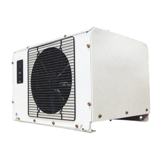
- Page 42 22147409 90CFM Cooler Assembly 22489389 60CFM Cooler Assembly Manual P/N 22189203 (01/17/2005)
- Page 43 Manual P/N 22189203 (01/17/2005)
- Page 44 22173538 Manual P/N 22189203 (01/17/2005)
- Page 45 UNLOADER ASSEMBLY Manual P/N 22189203 (01/17/2005)
- Page 46 Separator Tank Manual P/N 22189203 (01/17/2005)
- Page 47 Manual P/N 22189203 (01/17/2005)
- Page 48 Manual P/N 22189203 (01/17/2005)
- Page 49 AIR / OIL / HYDRAULIC PIPING Manual P/N 22189203 (01/17/2005)
- Page 50 AIR / OIL / HYDRAULIC PIPING Manual P/N 22189203 (01/17/2005)
- Page 51 AIR / OIL / HYDRAULIC PIPING PARTS LIST ITEM NO PART NO. DESCRIPTION 95946059 1/8 NIPPLE 95930301 BSHG RDCNPT025X012 95954095 ELB, .25 NPT 22184717 V CHK, .041 ORF 95942785 NIP LGNPT075X800 35310960 HOSE ASSY, –4 X 10 35114545 TEE 1/4 RUN 35301126 ELB 90 DEG 1/8NPT X –6 54433420...
- Page 52 Wiring Diagram Manual P/N 22189203 (01/17/2005)
- Page 53 54629977 DECAL, OIL DRAIN 54640024 DECAL, GENUINE PARTS 54604970 DECAL, FILL PLUG 54640164 DECAL, AIREND WARRANTY 22182315 DECAL, LIFT POINT 22191720 DECAL, GENERAL DATA (90CFM) 22486617 DECAL, GENERAL DATA (60CFM) 54568795 DECAL, HIGH PRESSURE AIR 43215037 DECAL, MAXIMUM SPEED 22207872 DECAL, VERTICAL GAGE LOCATION 54672175 DECAL, SWOOSH...
Need help?
Do you have a question about the HP60CMH and is the answer not in the manual?
Questions and answers