GORMAN-RUPP PAH Series Installation, Operation, And Maintenance Manual With Parts List
Hide thumbs
Also See for PAH Series:

Related Manuals for GORMAN-RUPP PAH Series


Summary of Contents for GORMAN-RUPP PAH Series
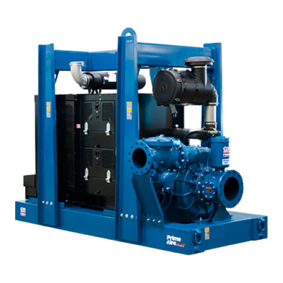
- Page 1 OM-07186-01 June 19, 2018 INSTALLATION, OPERATION, AND MAINTENANCE MANUAL WITH PARTS LIST PAH SERIESr PUMP MODEL PAH10A60-C18 GORMAN‐RUPP PUMPS www.grpumps.com 2018 Gorman‐Rupp Pumps Printed in U.S.A.
- Page 2 Register your new Gorman‐Rupp pump online at www.grpumps.com/register. Valid serial number and e‐mail address required. The engine exhaust from this product contains chemicals known to the State of California to cause cancer, birth defects or other reproductive harm. RECORD YOUR PUMP MODEL AND SERIAL NUMBER Please record your pump model and serial number in the spaces provided below.
-
Page 3: Table Of Contents
TABLE OF CONTENTS INTRODUCTION ..........PAGE I - 1 SAFETY ‐... - Page 4 TABLE OF CONTENTS (continued) Engine Fuel Filter ............PAGE C - 4 Engine Oil .
-
Page 5: Introduction
PAH SERIES OM-07186 INTRODUCTION Thank You for purchasing a Gorman‐Rupp pump. HAZARD AND INSTRUCTION Read this manual carefully to learn how to safely DEFINITIONS install and operate your pump. Failure to do so could result in personal injury or damage to the The following are used to alert maintenance per... -
Page 6: Safety - Section A
PAH SERIES OM-07186 SAFETY ‐ SECTION A This information applies to Prime Aire hands and clothing away from the unit to Series pumps. Refer to the manual ac prevent injury during automatic opera companying the engine or power tion. Disconnect the positive battery source before attempting to begin oper... - Page 7 OM-07186 PAH SERIES necessary and keep personnel away in place over the rotating parts. Ex from suspended objects. posed rotating parts can catch clothing, fingers or tools, causing severe injury to personnel. After the pump has been installed, make certain that the pump and all piping or hose connections are tight, properly Make sure the pump is level.
-
Page 8: Installation - Section B
PAH SERIES OM-07186 INSTALLATION - SECTION B Review all SAFETY information in Section A. configuration, and priming must be tailored to the specific application. Since the pressure supplied Since pump installations are seldom identical, this to the pump is critical to performance and safety,... -
Page 9: Battery Installation
OM-07186 PA SERIES c. Carefully read all tags, decals, and markings POSITIONING PUMP on the pump assembly, and perform all duties indicated. Note that the pump shaft rotates in the required direction. Death or serious personal injury and damage to the pump or components can occur if proper lifting procedures are not observed. -
Page 10: Suction And Discharge Piping
PAH SERIES OM-07186 Connections to Pump including the bearings, shaft and/or bear ing housing may occur if the pump is oper Before tightening a connecting flange, align it ex ated for an extended period of time on an actly with the pump port. Never pull a pipe line into unlevel surface. -
Page 11: Sealing
OM-07186 PA SERIES If a strainer not furnished with the pump is installed If it is necessary to position inflow close to the suc by the pump user, make certain that the total area tion inlet, install a baffle between the inflow and the of the openings in the strainer is at least three or suction inlet at a distance 1‐1/2 times the diameter four times the cross section of the suction line, and... -
Page 12: Discharge Lines
PAH SERIES OM-07186 Figure 2. Recommended Minimum Suction Line Submergence vs. Velocity DISCHARGE LINES Siphoning If the application involves a high discharge head, gradually close the discharge Do not terminate the discharge line at a level lower than that of the liquid being pumped unless a si... -
Page 13: Float Switch Installation
OM-07186 PA SERIES Float Switch Installation pipe is available, attach the float switch cable to the standpipe in the sump at the approxi mate desired liquid level. The Float Switch autostart system employs either a single or double float switch, where a bulb raises or lowers (floats) with the liquid level, thus activating b. - Page 14 PAH SERIES OM-07186 that the liquid in the priming chamber never fully Next, install a drain line between the pump drain freezes. and the wet well or sump. This line must remain submerged in the liquid below the pump down lev...
-
Page 15: Operation - Section C
OM-07186 PAH SERIES OPERATION - SECTION C OPERATION Make sure the pump is level. Lower the jack stands and chock the wheels, if so equipped. Review all SAFETY information in Section A. Follow the instructions on all tags, labels and decals attached to the pump. -
Page 16: Operation In Extreme Heat
OM-07186 PAH SERIES and system operating pressure. Do not operate Leakage below the recommended operating speed (if appli cable). Once the pump is fully primed, no leakage should be visible at pump mating surfaces, or at pump connections or fittings. Keep all line connections and fittings tight to maintain maximum pump effi... -
Page 17: Strainer Check
OM-07186 PAH SERIES Strainer Check Should any of the safety features cause the engine to shut down, the cause must be determined and corrected before putting the unit back into service. Check the strainer regularly, and clean it as neces... - Page 18 OM-07186 PAH SERIES tenance and Repair). Bearing overheating can COLD WEATHER PRESERVATION also be caused by shaft misalignment and/or ex cessive vibration. If the pump will be idle for an extended period of When pumps are first started, the bearings may time in below freezing conditions, drain the pump seem to run at temperatures above normal.
- Page 19 OM-07186 PAH SERIES TROUBLESHOOTING - SECTION D Review all SAFETY information in Section A. 5. Close the suction and discharge valves. 6. Vent the pump slowly and cau tiously. 7. Drain the pump. Before attempting to open or service the pump: 1.
- Page 20 OM-07186 PAH SERIES TROUBLE POSSIBLE CAUSE PROBABLE REMEDY Check strainer and clean if neces Strainer clogged. PUMP STOPS OR FAILS TO DELIVER sary. RATED FLOW OR Check and clean check valve. Discharge check valve clogged. PRESSURE (cont.) Suction intake not submerged at Check installation and correct proper level or sump too small.
- Page 21 OM-07186 PAH SERIES TROUBLE POSSIBLE CAUSE PROBABLE REMEDY BEARINGS RUN Bearing temperature is high, but Check bearing temperature regu TOO HOT within limits. larly to monitor any increase. Low or incorrect lubricant. Check for proper type and level of lubricant.
- Page 22 OM-07186 PAH SERIES Preventive Maintenance Schedule Service Interval* Item Daily Weekly Monthly Semi‐ Annually Annually General Condition (Temperature, Unusual Noises or Vibrations, Cracks, Leaks, Loose Hardware, Etc.) Pump Performance (Gauges, Speed, Flow) Bearing Lubrication Seal Lubrication (And Packing Adjustment, If So Equipped) V‐Belts (If So Equipped)
- Page 23 OM-07186 PAH SERIES PUMP MAINTENANCE AND REPAIR - SECTION E MAINTENANCE AND REPAIR OF THE WEARING PARTS OF THE PUMP WILL MAINTAIN PEAK OPERATING PERFORMANCE. STANDARD PERFORMANCE FOR PUMP MODEL PAH10A60-C18 Based on 70 F (21 C) clear water at sea level Contact the Gorman‐Rupp Company to verify per...
- Page 24 OM-07186 PAH SERIES PARTS PAGE ILLUSTRATION Figure 1. Pump Model PAH10A60-C18 PAGE E - 2 MAINTENANCE & REPAIR...
- Page 25 OM-07186 PAH SERIES PARTS LIST Pump Model PAH10A60-C18 (From S/N 1686808 Up) If your pump serial number is followed by an “N”, your pump is NOT a standard production model. Contact the Gorman‐Rupp Company to verify performance or part numbers.
- Page 26 OM-07186 PAH SERIES ILLUSTRATION 15 16 51 50 22 23 Figure 2. Power Unit Kit PAGE E - 4 MAINTENANCE & REPAIR...
- Page 27 OM-07186 PAH SERIES PARTS LIST Power Unit Kit ITEM PART NAME PART ITEM PART NAME PART NUMBER NUMBER BASE/FUEL TANK ASSY 41553-038 24150 CLAMP W/CUSHION 27111-347 CAT ENG W/ COMPRSSR 29236-482 HOSE .50 ID X 93" LG 18513-303 EXHAUST COVER...
- Page 28 OM-07186 PAH SERIES ILLUSTRATION TO FUEL SUPPLY ATTACH TO FUEL RETURN ATTACH TO LIFT BAIL 13 14 PLUMB TO COMPRESSOR DETAIL A Figure 3. Power Unit Kit (cont'd) PAGE E - 6 MAINTENANCE & REPAIR...
- Page 29 OM-07186 PAH SERIES PARTS LIST Power Unit Kit ITEM PART NAME PART ITEM PART NAME PART NUMBER NUMBER BASE/FUEL TANK ASSY 41553-038 24150 CLAMP W/CUSHION 27111-347 CAT ENG W/ COMPRSSR 29236-482 HOSE .50 ID X 93" LG 18513-303 EXHAUST COVER...
- Page 30 OM-07186 PAH SERIES ILLUSTRATION TO ENGINE AUX COMPRESSOR Figure 4. Pump End Assembly PAGE E - 8 MAINTENANCE & REPAIR...
- Page 31 OM-07186 PAH SERIES PARTS LIST Pump End Assembly ITEM PART NAME PART ITEM PART NAME PART NUMBER NUMBER CHECK VALVE KIT 10" 48274-007 WEAR RING 38691-639 11010 -CHECK VALVE 26642-127 STUD C1414 15991 -COVER O‐RING 25152-463 GASKET 38685-808 18000 SUCT SUPPORT ASSY...
- Page 32 OM-07186 PAH SERIES ILLUSTRATION Figure 5. Repair Rotating Assembly PAGE E - 10 MAINTENANCE & REPAIR...
- Page 33 OM-07186 PAH SERIES PARTS LIST Repair Rotating Assembly ITEM PART PART NAME NUMBER SOCKET HEAD CAP SCREW DM1206 15991 WASHER NORD-LOCK 3/4" 21177-224 IMPELLER WASHER 31167-041 17000 ROLL PIN S2197 IMPELLER 38621-783 11010 3.25" MECH SEAL 25285-823 SHAFT SLEEVE 31163-023 17000 O‐RING...
- Page 34 OM-07186 PAH SERIES ILLUSTRATION Figure 6. Priming Chamber Kit PARTS LIST ITEM PART PART NAME NUMBER BALL VALVE 26631-054 STREET ELBOW RS16 11999 PRIMING CHAMBER ASSEMBLY 46112-709 HEX NUT D08 15991 LOCK WASHER J08 15991 STUD C0809 15991 BAFFLE 31113-011 17000...
- Page 35 OM-07186 PAH SERIES ILLUSTRATION Figure 7. Priming Chamber Assembly PARTS LIST ITEM PART PART NAME NUMBER PRIMING VALVE 26664-007 -ORIFICE BUTTON 26688-021 HEX HD CAPSCREW B0806 15991 LOCKWASHER J08 15991 PRIMING VALVE GASKET 38683-657 19060 PRIMING CHAMBER 38343-020 10000 STRAINER ASSY...
- Page 36 OM-07186 PAH SERIES ILLUSTRATION Figure 8. Drive Assembly PARTS LIST ITEM PART PART NAME NUMBER COUPLING KIT - SAE 18 48112-024 -PERIFLEX COUPLING 24391-116 -BUSHING 24131-071 -LOCK WASHER J10 15991 -SOCKET HEAD CAP SCREW B1008 15991 HEX HEAD CAP SCREW...
- Page 37 OM-07186 PAH SERIES ILLUSTRATION Figure 9. Venturi Assembly PARTS LIST ITEM PART PART NAME NUMBER BRACKET 34266-152 15080 VENTURI 26817-006 REDUCER PIPE COUPLING AE1612 15079 PIPE NIPPLE T1608 15079 CHECK VALVE 26641-093 HEX NUT D06 15991 LOCK WASHER J06 15991...
- Page 38 OM-07186 PAH SERIES PUMP AND SEAL DISASSEMBLY pump integrity are compromised by such practices. AND REASSEMBLY Review all SAFETY information in Section A. Follow the instructions on all tags, label and de cals attached to the pump. Before attempting to open or service the...
- Page 39 Remove the hex nut and lock washer securing the orifice button to the linkage bar and unscrew the orifice button from the linkage bar. Use Only Genuine Gorman-Rupp re placement parts. Failure to do so may cre Discharge Check Valve Removal and ate a hazard and damage the pump or di...
- Page 40 OM-07186 PAH SERIES ing by a press fit. If replacement is required, re Slide a pair of stiff wires with hooked ends along move the set screws (20) and install two 3/8-16 the shaft and hook the stationary seat from the UNC-2B capscrews (not supplied) at least 1-1/4 back side.
- Page 41 OM-07186 PAH SERIES Remove any leveling shims used under the casing be cleaned and inspected in place. It is mounting feet. Tie and tag the shims for ease of strongly recommended that the bearings reassembly. be replaced any time the shaft and bear...
- Page 42 OM-07186 PAH SERIES Shaft and Bearing Reassembly and Installation (Figure 5) When installing the bearings onto the Clean and inspect the bearings as indicated in shaft, never press or hit against the outer Shaft and Bearing Removal and Disassembly. race, balls, or ball cage. Press only on the inner race.
- Page 43 OM-07186 PAH SERIES With the flexible portion of the coupling and the bushing properly positioned on the shaft, tighten the two bushing setscrews in an alternating se quence until the bushing and coupling are fully se When installing the shaft and bearings into cured.
- Page 44 OM-07186 PAH SERIES Seal Reassembly and Installation Reusing an old seal could result in prema ture failure. (Figures 5 and 10) Handle the seal parts with extreme care to prevent Clean the seal cavity and shaft with a cloth soaked damage.
- Page 45 OM-07186 PAH SERIES RETAINER SEAL PLATE SPRING ROLL PIN CENTERING WASHER SLEEVE O‐RING SHAFT SLEEVE SHAFT IMPELLER SHIMS IMPELLER SHAFT ROTATING BELLOWS ELEMENT STATIONARY SEAT IMPELLER O‐RING SPRING Figure 10. Seal Assembly excessive wear will occur as the shaft turns.
- Page 46 OM-07186 PAH SERIES flush with the undercut end of the sleeve. Slide the Carefully position the pump casing over the impel shaft sleeve and rotating portion of the seal onto ler. Install the hardware (7 and 8) on the studs (5) the shaft until the sealing faces contact.
- Page 47 OM-07186 PAH SERIES bar. Proper adjustment is achieved when the ori Bearings fice button fully seats against the orifice before the (Figure 5) linkage bar on the float bottoms against the threads on the orifice button. When adjustment is The pedestal was fully lubricated when shipped complete, install and tighten the lock washer and from the factory.
- Page 48 For Warranty Information, Please Visit www.grpumps.com/warranty or call: U.S.: 419-755-1280 Canada: 519-631-2870 International: +1-419-755-1352 GORMAN‐RUPP PUMPS...
Need help?
Do you have a question about the PAH Series and is the answer not in the manual?
Questions and answers