GORMAN-RUPP PAH Series Installation, Operation, And Maintenance Manual With Parts List
Hide thumbs
Also See for PAH Series:

Subscribe to Our Youtube Channel
Related Manuals for GORMAN-RUPP PAH Series


Summary of Contents for GORMAN-RUPP PAH Series
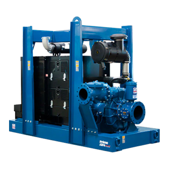
- Page 1 OM-06662-02 July 6, 2016 INSTALLATION, OPERATION, AND MAINTENANCE MANUAL WITH PARTS LIST PAH SERIESr PUMP MODEL PAH10A60C-C18 GORMAN‐RUPP PUMPS www.grpumps.com 2016 Gorman‐Rupp Pumps Printed in U.S.A.
- Page 2 Register your new Gorman‐Rupp pump online at www.grpumps.com/register. Valid serial number and e‐mail address required. The engine exhaust from this product contains chemicals known to the State of California to cause cancer, birth defects or other reproductive harm. RECORD YOUR PUMP MODEL AND SERIAL NUMBER Please record your pump model and serial number in the spaces provided below.
-
Page 3: Table Of Contents
TABLE OF CONTENTS INTRODUCTION ..........PAGE I - 1 SAFETY ‐... - Page 4 TABLE OF CONTENTS (continued) Safety Shutdown System ..........PAGE C - 3 PERIODIC CHECKS .
-
Page 5: Introduction
PAH SERIES OM-06662 INTRODUCTION Thank You for purchasing a Gorman‐Rupp pump. HAZARD AND INSTRUCTION Read this manual carefully to learn how to safely DEFINITIONS install and operate your pump. Failure to do so could result in personal injury or damage to the The following are used to alert maintenance per... -
Page 6: Safety - Section A
PAH SERIES OM-06662 SAFETY ‐ SECTION A This information applies to Prime Aire damage the pump or endanger person Series pumps. Refer to the manual ac nel as a result of pump failure. companying the engine or power source before attempting to begin oper... - Page 7 OM-06662 PAH SERIES pipe plugs, or fittings from an over heated pump. Vapor pressure within the pump can cause parts being disen gaged to be ejected with great force. Al Do not operate an internal combustion low the pump to cool completely before engine in an explosive atmosphere.
-
Page 8: Installation - Section B
PAH SERIES OM-06662 INSTALLATION - SECTION B Review all SAFETY information in Section A. configuration, and priming must be tailored to the specific application. Since the pressure supplied Since pump installations are seldom identical, this to the pump is critical to performance and safety,... -
Page 9: Battery Installation
OM-06662 PA SERIES c. Carefully read all tags, decals, and markings POSITIONING PUMP on the pump assembly, and perform all duties indicated. Note that the pump shaft rotates in the required direction. Death or serious personal injury and damage to the pump or components can occur if proper lifting procedures are not observed. -
Page 10: Suction And Discharge Piping
PAH SERIES OM-06662 Connections to Pump including the bearings, shaft and/or bear ing housing may occur if the pump is oper Before tightening a connecting flange, align it ex ated for an extended period of time on an actly with the pump port. Never pull a pipe line into unlevel surface. -
Page 11: Sealing
OM-06662 PA SERIES If a strainer not furnished with the pump is installed If it is necessary to position inflow close to the suc by the pump user, make certain that the total area tion inlet, install a baffle between the inflow and the of the openings in the strainer is at least three or suction inlet at a distance 1‐1/2 times the diameter four times the cross section of the suction line, and... -
Page 12: Discharge Lines
PAH SERIES OM-06662 Figure 2. Recommended Minimum Suction Line Submergence vs. Velocity DISCHARGE LINES Siphoning If the application involves a high discharge head, gradually close the discharge Do not terminate the discharge line at a level lower than that of the liquid being pumped unless a si... -
Page 13: Float Switch Installation
OM-06662 PA SERIES Float Switch Installation pipe is available, attach the float switch cable to the standpipe in the sump at the approxi mate desired liquid level. The Float Switch autostart system employs either a single or double float switch, where a bulb raises or lowers (floats) with the liquid level, thus activating b. - Page 14 PAH SERIES OM-06662 that the liquid in the priming chamber never fully Next, install a drain line between the pump drain freezes. and the wet well or sump. This line must remain submerged in the liquid below the pump down lev...
-
Page 15: Operation - Section C
OM-06662 PAH SERIES OPERATION - SECTION C OPERATION Make sure the pump is level. Lower the jack stands and chock the wheels, if so equipped. Review all SAFETY information in Section A. Follow the instructions on all tags, labels and decals attached to the pump. -
Page 16: Operation In Extreme Heat
OM-06662 PAH SERIES and system operating pressure. Do not operate the source of the leak, check the point of installa below the recommended operating speed (if appli tion of the vacuum gauge. cable). Liquid Temperature And Overheating The maximum liquid temperature for this pump is F (71 C). -
Page 17: Stopping
OM-06662 PAH SERIES STOPPING shutdown before putting the unit back into service. Consult the factory for ad ditional information. Manual Stopping PERIODIC CHECKS In the manual mode, reduce the throttle speed slowly, and allow the engine to idle briefly before Seal Cavity And Bearing Lubrication turning the keyswitch to `OFF'. - Page 18 OM-06662 PAH SERIES Consult the manual accompanying the engine, been pumping liquids containing a large amount of and change the oil filter periodically as indicated. If solids, drain the pump, and flush it thoroughly with operated under extremely dusty conditions, clean water.
- Page 19 OM-06662 PAH SERIES TROUBLESHOOTING - SECTION D Review all SAFETY information in Section A. Before attempting to open or service the pump: 1. Familiarize yourself with this manual. 2. Shut down the engine and discon nect the positive battery cable to en...
- Page 20 OM-06662 PAH SERIES TROUBLE POSSIBLE CAUSE PROBABLE REMEDY Check strainer and clean if neces Strainer clogged. PUMP STOPS OR FAILS TO DELIVER sary. RATED FLOW OR Check and clean check valve. Discharge check valve clogged. PRESSURE (cont.) Suction intake not submerged at Check installation and correct proper level or sump too small.
- Page 21 OM-06662 PAH SERIES TROUBLE POSSIBLE CAUSE PROBABLE REMEDY BEARINGS RUN Bearing temperature is high, but Check bearing temperature regu TOO HOT within limits. larly to monitor any increase. Low or incorrect lubricant. Check for proper type and level of lubricant.
- Page 22 OM-06662 PAH SERIES Preventive Maintenance Schedule Service Interval* Item Daily Weekly Monthly Semi‐ Annually Annually General Condition (Temperature, Unusual Noises or Vibrations, Cracks, Leaks, Loose Hardware, Etc.) Pump Performance (Gauges, Speed, Flow) Bearing Lubrication Seal Lubrication (And Packing Adjustment, If So Equipped) V‐Belts (If So Equipped)
- Page 23 OM-06662 PAH SERIES PUMP MAINTENANCE AND REPAIR - SECTION E MAINTENANCE AND REPAIR OF THE WEARING PARTS OF THE PUMP WILL MAINTAIN PEAK OPERATING PERFORMANCE. STANDARD PERFORMANCE FOR PUMP MODEL PAH10A60C-C18 Based on 70 F (21 C) clear water at sea level Contact the Gorman‐Rupp Company to verify per...
- Page 24 OM-06662 PAH SERIES PARTS PAGE ILLUSTRATION Figure 1. Pump Model PAH10A60C-C18 PAGE E - 2 MAINTENANCE & REPAIR...
- Page 25 OM-06662 PAH SERIES PARTS LIST Pump Model PAH10A60C-C18 (From S/N 1627218 Up) If your pump serial number is followed by an “N”, your pump is NOT a standard production model. Contact the Gorman‐Rupp Company to verify performance or part numbers.
- Page 26 OM-06662 PAH SERIES ILLUSTRATION Figure 2. Power Unit Kit PAGE E - 4 MAINTENANCE & REPAIR...
- Page 27 OM-06662 PAH SERIES PARTS LIST Power Unit Kit ITEM PART NAME PART ITEM PART NAME PART NUMBER NUMBER BASE/FUEL TANK ASSY 41553-038 24150 8D BATTERY 29331-541 CAT C18 ENGINE 29236-481 4/O CABLE SUB ASS'Y 47311-701 EXHAUST COVER 29334-421 4/O CABLE SUB ASS'Y...
- Page 28 OM-06662 PAH SERIES ILLUSTRATION Figure 3. Power Unit Kit PAGE E - 6 MAINTENANCE & REPAIR...
- Page 29 OM-06662 PAH SERIES PARTS LIST Power Unit Kit ITEM PART NAME PART ITEM PART NAME PART NUMBER NUMBER BASE/FUEL TANK ASSY 41553-038 24150 8D BATTERY 29331-541 CAT C18 ENGINE 29236-481 4/O CABLE SUB ASS'Y 47311-701 EXHAUST COVER 29334-421 4/O CABLE SUB ASS'Y...
- Page 30 OM-06662 PAH SERIES ILLUSTRATION Figure 4. Pump End Assembly PAGE E - 8 MAINTENANCE & REPAIR...
- Page 31 OM-06662 PAH SERIES PARTS LIST Pump End Assembly ITEM PART NAME PART ITEM PART NAME PART NUMBER NUMBER PUMP CASING SEE NOTE BELOW STUD C1414 15991 PIPE PLUG P04 15079 SUCTION SUPP ASSY 41888-298 24150 WEAR RING 38691-639 11010 HEX HEAD CAP SCREW...
- Page 32 OM-06662 PAH SERIES ILLUSTRATION Figure 5. Repair Rotating Assembly PAGE E - 10 MAINTENANCE & REPAIR...
- Page 33 OM-06662 PAH SERIES PARTS LIST Repair Rotating Assembly ITEM PART PART NAME NUMBER SOCKET HEAD CAP SCREW DM1206 15991 WASHER NORD-LOCK 3/4" 21177-224 IMPELLER WASHER 31167-041 17000 ROLL PIN S2197 IMPELLER 38621-783 11010 3.25" MECH SEAL 25285-823 SHAFT SLEEVE 31163-023 17000 O‐RING...
- Page 34 OM-06662 PAH SERIES ILLUSTRATION Figure 6. Air Compressor Assembly PAGE E - 12 MAINTENANCE & REPAIR...
- Page 35 OM-06662 PAH SERIES PARTS LIST Air Compressor Assembly ITEM PART PART NAME NUMBER VANAIR 60 CFM COMPRESSOR 26813-114 MOUNTING BRACKET 38138-090 13000 LOCK WASHER 21171-510 HEX HEAD CAP SCREW 22645-135 SHAFT COLLAR 24118-035 ADAPTER SHAFT 38513-420 16040 N0405 15990 FLANGE BEARING...
- Page 36 OM-06662 PAH SERIES ILLUSTRATION Figure 7. Priming Chamber Kit ITEM PART PART NAME NUMBER BALL VALVE 26631-054 STREET ELBOW RS16 11999 PRIMING CHAMBER ASSEMBLY 46112-709 HEX NUT D08 15991 LOCK WASHER J08 15991 STUD C0809 15991 BAFFLE 31113-011 17000 GASKET...
- Page 37 OM-06662 PAH SERIES ILLUSTRATION Figure 8. Priming Chamber Assembly ITEM PART PART NAME NUMBER PRIMING VALVE 26664-007 -ORIFICE BUTTON 26688-021 HEX HD CAPSCREW B0806 15991 LOCKWASHER J08 15991 PRIMING VALVE GASKET 38683-657 19060 PRIMING CHAMBER 38343-020 10000 STRAINER ASSY 46641-222 17000 INDICATES PARTS RECOMMENDED FOR STOCK MAINTENANCE &...
- Page 38 OM-06662 PAH SERIES ILLUSTRATION Figure 9. 44162-184 Drive Assembly ITEM PART PART NAME NUMBER COUPLING KIT - SAE 18 48112-024 -PERIFLEX COUPLING 24391-116 -BUSHING 24131-071 -LOCK WASHER J10 15991 -SOCKET HEAD CAP SCREW B1008 15991 HEX HEAD CAP SCREW B0807 15991...
- Page 39 OM-06662 PAH SERIES ILLUSTRATION Figure 10. Venturi Assembly ITEM PART PART NAME NUMBER BRACKET 34266-075 15080 VENTURI 26817-007 REDUCER PIPE COUPLING AE2016 15079 PIPE NIPPLE T1608 15079 CHECK VALVE 26641-093 LOCK WASHER J06 15991 HEX NUT D06 15991 HEX HEAD CAP SCREW...
- Page 40 OM-06662 PAH SERIES PUMP AND SEAL DISASSEMBLY pump integrity are compromised by such practices. AND REASSEMBLY Review all SAFETY information in Section A. Follow the instructions on all tags, label and de cals attached to the pump. Before attempting to open or service the...
- Page 41 OM-06662 PAH SERIES Remove the hex nut and lock washer securing the subject to automatic restart. Keep orifice button to the linkage bar and unscrew the hands and clothing away from the unit to orifice button from the linkage bar.
- Page 42 OM-06662 PAH SERIES Impeller and Wear Ring Removal with the impeller side down. Use a wooden dowel or other suitable tool to press on the back side of (Figure 5) the stationary seat until the seat and O‐ring can be removed.
- Page 43 OM-06662 PAH SERIES bushing and sprocket (8) off the shaft. Remove the After removing the shaft and bearings, clean and drive key (30, Figure 5). inspect the bearings in place as follows. It is not necessary to remove the outer ring of the coupling from the engine flywheel unless the cou...
- Page 44 OM-06662 PAH SERIES If bearing replacement is required, straighten the time onto the shaft until fully seated against the tab on the bearing lock washer (27). Use a spanner shaft shoulders. This should be done quickly, in wrench to remove the bearing lock nut (26). Re...
- Page 45 OM-06662 PAH SERIES sembled bearings into the bearing housing until Align the keyway in the bushing (3) with the shaft key and slide the bushing onto the shaft. Slide the the retaining ring on the outboard bearing seats flexible portion of the coupling (2) over the bushing against the pedestal.
- Page 46 OM-06662 PAH SERIES Secure the drive flange (23, Figure 5) to the engine precautions printed on solvent contain bellhousing with the previously removed hardware ers. (6 and 7). Secure the pedestal to the support (26, Figure 4) with the previously removed hardware (24 and 25, Figure 4).
- Page 47 OM-06662 PAH SERIES RETAINER SEAL PLATE SPRING ROLL PIN CENTERING WASHER SLEEVE O‐RING SHAFT SLEEVE SHAFT IMPELLER SHIMS IMPELLER SHAFT ROTATING BELLOWS ELEMENT STATIONARY SEAT IMPELLER O‐RING SPRING Figure 11. Seal Assembly excessive wear will occur as the shaft turns.
- Page 48 OM-06662 PAH SERIES flush with the undercut end of the sleeve. Slide the Carefully position the pump casing over the impel shaft sleeve and rotating portion of the seal onto ler. Install the hardware (8 and 9) on the studs (6) the shaft until the sealing faces contact.
- Page 49 OM-06662 PAH SERIES bar. Proper adjustment is achieved when the ori Bearings fice button fully seats against the orifice before the (Figure 5) linkage bar on the float bottoms against the threads on the orifice button. When adjustment is The pedestal was fully lubricated when shipped complete, install and tighten the lock washer and from the factory.
- Page 50 For Warranty Information, Please Visit www.grpumps.com/warranty or call: U.S.: 419-755-1280 Canada: 519-631-2870 International: +1-419-755-1352 GORMAN‐RUPP PUMPS...
Need help?
Do you have a question about the PAH Series and is the answer not in the manual?
Questions and answers