GORMAN-RUPP PA Series Installation, Operation And Maintenance Manual
Hide thumbs
Also See for PA Series:
- Installation, operation and maintenance manual (48 pages) ,
- Installation, operation, and maintenance manual with parts list (47 pages) ,
- Manual (46 pages)

Subscribe to Our Youtube Channel
Related Manuals for GORMAN-RUPP PA Series


Summary of Contents for GORMAN-RUPP PA Series
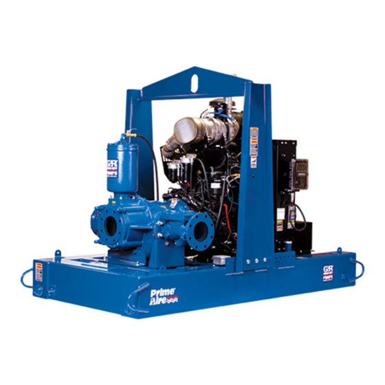
- Page 1 OM-07128-01 July 17, 2017 INSTALLATION, OPERATION, AND MAINTENANCE MANUAL WITH PARTS LIST PA SERIES PUMP MODEL PAV3B60C-3TNV80F FT4 GORMAN‐RUPP PUMPS www.grpumps.com 2017 Gorman‐Rupp Pumps Printed in U.S.A.
- Page 2 Register your new Gorman‐Rupp pump online at www.grpumps.com Valid serial number and e‐mail address required. The engine exhaust from this product contains chemicals known to the State of California to cause cancer, birth defects or other reproductive harm. RECORD YOUR PUMP MODEL AND SERIAL NUMBER Please record your pump model and serial number in the spaces provided below.
-
Page 3: Table Of Contents
TABLE OF CONTENTS INTRODUCTION ..........PAGE I - 1 SAFETY ‐... - Page 4 TABLE OF CONTENTS (continued) COLD WEATHER PRESERVATION ......... . . PAGE C - 3 TROUBLESHOOTING - SECTION D .
-
Page 5: Introduction
PA SERIES OM-07128 INTRODUCTION Thank You for purchasing a Gorman‐Rupp pump. HAZARD AND INSTRUCTION Read this manual carefully to learn how to safely DEFINITIONS install and operate your pump. Failure to do so could result in personal injury or damage to the The following are used to alert maintenance per... -
Page 6: Safety - Section A
PA SERIES OM-07128 SAFETY ‐ SECTION A This information applies to Prime Aire hands and clothing away from the unit to Series pumps. Refer to the manual ac prevent injury during automatic opera companying the engine or power tion. Disconnect the positive battery source before attempting to begin oper... - Page 7 OM-07128 PA SERIES necessary and keep personnel away adequate protective clothing when from suspended objects. working on the pump or piping. Do not operate the pump without guards After the pump has been installed, make in place over the rotating parts. Ex...
-
Page 8: Installation - Section B
PA SERIES OM-07128 INSTALLATION - SECTION B Review all SAFETY information in Section A. configuration, and priming must be tailored to the specific application. Since the pressure supplied Since pump installations are seldom identical, this to the pump is critical to performance and safety,... -
Page 9: Battery Installation
OM-07128 PA SERIES c. Carefully read all tags, decals, and markings sion. Connect and tighten the positive cable first, on the pump assembly, and perform all duties then the negative cable. indicated. Note that the pump shaft rotates in the required direction. -
Page 10: Suction And Discharge Piping
PA SERIES OM-07128 For engine driven units, the pump must be posi place by tightening the flange bolts and/or cou tioned as level as possible to ensure sufficient lubri plings. cation and fuel supply to the engine. Lines near the pump must be independently sup... -
Page 11: Sealing
OM-07128 PA SERIES of the openings in the strainer is at least three or If it is necessary to position inflow close to the suc four times the cross section of the suction line, and tion inlet, install a baffle between the inflow and the that the openings will not permit passage of solids suction inlet at a distance 1‐1/2 times the diameter... -
Page 12: Discharge Lines
PA SERIES OM-07128 Figure 2. Recommended Minimum Suction Line Submergence vs. Velocity DISCHARGE LINES Siphoning If the application involves a high discharge head, gradually close the discharge Do not terminate the discharge line at a level lower than that of the liquid being pumped unless a si... -
Page 13: Float Switch Installation
OM-07128 PA SERIES Float Switch Installation pipe is available, attach the float switch cable to the standpipe in the sump at the approxi mate desired liquid level. The Float Switch autostart system employs either a single or double float switch, where a bulb raises or lowers (floats) with the liquid level, thus activating b. - Page 14 PA SERIES OM-07128 that the liquid in the priming chamber never fully Next, install a drain line between the pump drain freezes. and the wet well or sump. This line must remain submerged in the liquid below the pump down lev...
-
Page 15: Operation - Section C
OM-07128 PA SERIES OPERATION - SECTION C Review all SAFETY information in Section A. down the pump and consult Maintenance and Repair, Section E for further details. Follow the instructions on all tags, labels and STARTING decals attached to the pump. -
Page 16: Routine Operation
OM-07128 PA SERIES check for debris which may be preventing the Pump Vacuum Check check valve for seating, or for damage to the check Read the vacuum gauge with the pump primed valve itself. If the check valve requires replace... -
Page 17: Stopping
OM-07128 PA SERIES could result in personal injury or damage to the A sudden increase in bearing temperatures is a equipment. If backflushing is absolutely neces warning that the bearings are at the point of failing sary, liquid pressure must be limited to 50% of the to operate properly. - Page 18 OM-07128 PA SERIES TROUBLESHOOTING - SECTION D Review all SAFETY information in Section A. 5. Close the suction and discharge valves. 6. Vent the pump slowly and cau tiously. 7. Drain the pump. Before attempting to open or service the pump: 1.
- Page 19 OM-07128 PA SERIES TROUBLE POSSIBLE CAUSE PROBABLE REMEDY Check strainer and clean if neces Strainer clogged. PUMP STOPS OR FAILS TO DELIVER sary. RATED FLOW OR Check and clean check valve. Discharge check valve clogged. PRESSURE (cont.) Suction intake not submerged at Check installation and correct proper level or sump too small.
- Page 20 OM-07128 PA SERIES TROUBLE POSSIBLE CAUSE PROBABLE REMEDY BEARINGS RUN Bearing temperature is high, but Check bearing temperature regu TOO HOT within limits. larly to monitor any increase. Low or incorrect lubricant. Check for proper type and level of lubricant.
- Page 21 OM-07128 PA SERIES Preventive Maintenance Schedule Service Interval* Item Daily Weekly Monthly Semi‐ Annually Annually General Condition (Temperature, Unusual Noises or Vibrations, Cracks, Leaks, Loose Hardware, Etc.) Pump Performance (Gauges, Speed, Flow) Bearing Lubrication Seal Lubrication (And Packing Adjustment, If So Equipped) V‐Belts (If So Equipped)
- Page 22 OM-07128 PA SERIES PUMP MAINTENANCE AND REPAIR - SECTION E MAINTENANCE AND REPAIR OF THE WEARING PARTS OF THE PUMP WILL MAINTAIN PEAK OPERATING PERFORMANCE. STANDARD PERFORMANCE FOR PUMP MODEL PAV3B60C-3TNV80F FT4 Based on 70 F (21 C) clear water at sea level Contact the Gorman‐Rupp Company to verify per...
- Page 23 OM-07128 PA SERIES PARTS PAGE ILLUSTRATION 12 11 Figure 1. Pump Model PAV3B60C-3TNV80F FT4 PAGE E - 2 MAINTENANCE & REPAIR...
- Page 24 OM-07128 PA SERIES Pump Model PAV3B60C-3TNV80F FT4 PARTS LIST (From S/N 1641715 Up) If your pump serial number is followed by an “N”, your pump is NOT a standard production model. Contact the Gorman‐Rupp Company to verify part numbers. ITEM...
- Page 25 OM-07128 PA SERIES ILLUSTRATION Figure 2. Pump Model PAV3B60C-3TNV80F FT4 (cont'd) PAGE E - 4 MAINTENANCE & REPAIR...
- Page 26 OM-07128 PA SERIES Pump Model PAV3B60C-3TNV80F FT4 (cont'd) PARTS LIST (From S/N 1641715 Up) ITEM PART NAME PART ITEM PART NAME PART NUMBER NUMBER PUMP END ASSEMBLY 46183-133 FLAT WASHER K10 15991 LIFT BAIL ASSEMBLY 44715-043 24150 HEX HEAD CAP SCREW...
- Page 27 OM-07128 PA SERIES ILLUSTRATION SEE FIGURE 4 Figure 3. Pump End Assembly PAGE E - 6 MAINTENANCE & REPAIR...
- Page 28 OM-07128 PA SERIES Pump End Assembly PARTS LIST ITEM PART NAME PART ITEM PART NAME PART NUMBER NUMBER REPAIR ROTATING ASSY 44163-733 HEX HEAD CAP SCREW B1010S 15991 LOCK WASHER 21171-512 DISCHARGE ELBOW 38647-641 10000 HEX HEAD CAP SCREW 22644-224...
- Page 29 OM-07128 PA SERIES ILLUSTRATION Figure 4. Pump End Assembly (cont'd) PAGE E - 8 MAINTENANCE & REPAIR...
- Page 30 OM-07128 PA SERIES Pump End Assembly (cont'd) PARTS LIST Continued ITEM PART NAME PART ITEM PART NAME PART NUMBER NUMBER REPAIR ROTATING ASSY 44163-733 HEX HEAD CAP SCREW B1010S 15991 LOCK WASHER 21171-512 DISCHARGE ELBOW 38647-641 10000 HEX HEAD CAP SCREW...
- Page 31 OM-07128 PA SERIES ILLUSTRATION SEAL AREA DETAIL Figure 5. Repair Rotating Assembly PAGE E - 10 MAINTENANCE & REPAIR...
- Page 32 OM-07128 PA SERIES PARTS LIST Repair Rotating Assembly ITEM PART PART NAME NUMBER SOCKET HEAD CAP SCREW 22644-217 IMPELLER WASHER 31514-019 17000 IMPELLER 38614-844 11010 ADJ SHIM SET 2X 17090 SEAL ASSY 46513-171 FLAT HEAD CAP SCREW 22644-166 SEAL PLATE 38272-425 11010 O‐RING...
- Page 33 OM-07128 PA SERIES ILLUSTRATION Figure 6. Air Compressor Assembly PAGE E - 12 MAINTENANCE & REPAIR...
- Page 34 OM-07128 PA SERIES PARTS LIST Air Compressor Assembly ITEM PART PART NAME NUMBER AIR COMPRESSOR 26813-113 PIPE PLUG P04 15079 STREET ELBOW RS04 11999 TUBE 31962-001 14090 COMPRESSION FITTING 26311-067 PRESSURE RELIEF VALVE 26662-028 HOSE BARB FITTING 26523-446 CHECK VALVE...
- Page 35 OM-07128 PA SERIES PUMP AND SEAL DISASSEMBLY pump integrity are compromised by such practices. AND REASSEMBLY Review all SAFETY information in Section A. Follow the instructions on all tags, label and de Before attempting to open or service the cals attached to the pump.
- Page 36 OM-07128 PA SERIES the pump or component only as high as Gasket Cover necessary and keep personnel away from suspended objects. Float Float Use only replacement parts provided or Orifice approved by Gorman‐Rupp. Use of non‐ Button authorized parts may result in damage to...
- Page 37 OM-07128 PA SERIES (12) requires replacement. To remove the spool, Seal Removal disengage the hardware (7 and 8). See Figure 1, (Figure 5) disengage the hardware (31, 32, 33and 34) and re move the pump support bracket (21). Separate the...
- Page 38 OM-07128 PA SERIES See Figure 5 and remove the hardware (10 and 26) Place a block of wood against the impeller end of securing the mounting flange (27) to the engine the shaft (31) and tap the shaft and assembled bellhousing.
- Page 39 OM-07128 PA SERIES housing. Replace the bearings, shaft, or bearing done quickly, in one continuous motion, to prevent housing if the proper bearing fit is not achieved. the bearings from cooling and sticking on the shaft. After the bearings have been installed and allowed...
- Page 40 OM-07128 PA SERIES inboard oil seal on the shaft shoulder. Secure the If the flexible portion of the coupling was separated lip seal holder to the bearing housing with the hard from the engine flywheel for replacement, secure ware (10 and 11).
- Page 41 OM-07128 PA SERIES To ease installation of the seal, lubricate the shaft ring with a very small amount of light lubricating oil. sleeve O‐ring and the external stationary seat O‐ See Figure 9 for seal part identification. SEAL PLATE RETAINER...
- Page 42 OM-07128 PA SERIES onto the shaft. This action will press the stationary Handle the seal parts with extreme care to prevent seat into the seal plate bore. damage. Be careful not to contaminate precision finished faces; even fingerprints on the faces can shorten seal life.
- Page 43 OM-07128 PA SERIES the shaft keyway. Align the keyway of the impeller If the gasket (12) was removed, clean the mating with the shaft key and push the impeller onto the surfaces of the casing (10) and flange (37). Install...
- Page 44 OM-07128 PA SERIES mately 15 ounces (0,44 liter) of oil, or to the middle LUBRICATION of the sight gauge (25). Clean and reinstall the pipe (Figure 5) plug. Do not over‐lubricate the bearing housing. Over‐lubrication can cause the bearings to over‐...
- Page 45 For Warranty Information, Please Visit www.grpumps.com/warranty or call: U.S.: 419-755-1280 Canada: 519-631-2870 International: +1-419-755-1352 GORMAN‐RUPP PUMPS...
Need help?
Do you have a question about the PA Series and is the answer not in the manual?
Questions and answers