GORMAN-RUPP PAH SERIES Installation, Operation And Maintenance Manual
Hide thumbs
Also See for PAH SERIES:

Related Manuals for GORMAN-RUPP PAH SERIES


Summary of Contents for GORMAN-RUPP PAH SERIES
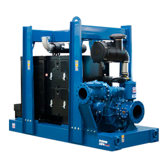
- Page 1 OM-07194-01 July 3, 2018 Rev. A 8/14/19 INSTALLATION, OPERATION, AND MAINTENANCE MANUAL WITH PARTS LIST PAH SERIESr PUMP MODEL PAH16A60‐B‐C18 GORMAN‐RUPP PUMPS www.grpumps.com 2018 Gorman‐Rupp Pumps Printed in U.S.A.
- Page 2 Register your new Gorman‐Rupp pump online at www.grpumps.com/register. Valid serial number and e‐mail address required. The engine exhaust from this product contains chemicals known to the State of California to cause cancer, birth defects or other reproductive harm. RECORD YOUR PUMP MODEL AND SERIAL NUMBER Please record your pump model and serial number in the spaces provided below.
-
Page 3: Table Of Contents
TABLE OF CONTENTS INTRODUCTION ..........PAGE I - 1 SAFETY ‐... - Page 4 TABLE OF CONTENTS (continued) Engine Fuel Filter ............PAGE C - 4 Engine Oil .
-
Page 5: Introduction
PAH SERIES OM-07194 INTRODUCTION Thank You for purchasing a Gorman‐Rupp pump. HAZARD AND INSTRUCTION Read this manual carefully to learn how to safely DEFINITIONS install and operate your pump. Failure to do so could result in personal injury or damage to the The following are used to alert maintenance per... -
Page 6: Safety - Section A
PAH SERIES OM-07194 SAFETY ‐ SECTION A This information applies to Prime Aire the positive battery cable before per Series pumps. Refer to the manual ac forming any maintenance. Failure to do companying the engine or power so may result in serious personal injury. - Page 7 OM-07194 PAH SERIES Do not operate the pump against a Make sure the pump is level. Lower jack closed discharge valve. If operated stands and chock the wheels, if so against a closed discharge valve, pump equipped. Use caution when positioning components will deteriorate, and the the skid‐mounted unit to prevent damage...
-
Page 8: Installation - Section B
PAH SERIES OM-07194 INSTALLATION - SECTION B Review all SAFETY information in Section A. configuration, and priming must be tailored to the specific application. Since the pressure supplied Since pump installations are seldom identical, this to the pump is critical to performance and safety,... -
Page 9: Battery Installation
OM-07194 PA SERIES c. Carefully read all tags, decals, and markings POSITIONING PUMP on the pump assembly, and perform all duties indicated. Note that the pump shaft rotates in the required direction. Death or serious personal injury and damage to the pump or components can occur if proper lifting procedures are not observed. -
Page 10: Suction And Discharge Piping
PAH SERIES OM-07194 Connections to Pump including the bearings, shaft and/or bear ing housing may occur if the pump is oper Before tightening a connecting flange, align it ex ated for an extended period of time on an actly with the pump port. Never pull a pipe line into unlevel surface. -
Page 11: Sealing
OM-07194 PA SERIES If a strainer not furnished with the pump is installed If it is necessary to position inflow close to the suc by the pump user, make certain that the total area tion inlet, install a baffle between the inflow and the of the openings in the strainer is at least three or suction inlet at a distance 1‐1/2 times the diameter four times the cross section of the suction line, and... -
Page 12: Discharge Lines
PAH SERIES OM-07194 Figure 2. Recommended Minimum Suction Line Submergence vs. Velocity DISCHARGE LINES Siphoning If the application involves a high discharge Do not terminate the discharge line at a level lower head, gradually close the discharge than that of the liquid being pumped unless a si... -
Page 13: Float Switch Installation
OM-07194 PA SERIES Refer to the information which follows for installa tom. Direct the suction line toward the flow, tion details for the liquid level sensing system pro and the float(s) away from the flow. If a stand vided with your pump. pipe is available, attach the float switch cable to the standpipe in the sump at the approxi... - Page 14 PAH SERIES OM-07194 ed liquid from the engine cooling system through the pump shuts off, providing for complete the priming chamber to heat the chamber and its drainage of the pump and priming hopper. contents. This method is particularly effective...
-
Page 15: Operation - Section C
OM-07194 PAH SERIES OPERATION - SECTION C OPERATION Review all SAFETY information in Section A. Make sure the pump is level. Lower jack Follow the instructions on all tags, labels and stands and chock the wheels, if so decals attached to the pump. -
Page 16: Operation In Extreme Heat
OM-07194 PAH SERIES and fittings tight to maintain maximum pump effi ciency. Pump Vacuum Check Never tamper with the governor to gain more power. The governor establishes Read the vacuum gauge with the pump primed safe operating limits that should not be and at operation speed. -
Page 17: Stopping
OM-07194 PAH SERIES vacuum suction gauge readings regularly to detect strainer blockage. Never introduce air or steam pressure into the Never disconnect any of the safety shut pump casing or piping to remove a blockage. This down features; this will void the warran... - Page 18 OM-07194 PAH SERIES Engine Fuel Filter and priming hopper to prevent damage from freez ing. Also, clean out any solids by flushing with a Consult the manual accompanying the engine, hose. Operate the pump for approximately one and change the fuel filter periodically as indicated.
- Page 19 OM-07194 PAH SERIES TROUBLESHOOTING - SECTION D Review all SAFETY information in Section A. 5. Close the suction and discharge valves. 6. Vent the pump slowly and cau tiously. 7. Drain the pump. Before attempting to open or service the pump: 1.
- Page 20 OM-07194 PAH SERIES TROUBLE POSSIBLE CAUSE PROBABLE REMEDY Check strainer and clean if neces Strainer clogged. PUMP STOPS OR FAILS TO DELIVER sary. RATED FLOW OR Check and clean check valve. Discharge check valve clogged. PRESSURE (cont.) Suction intake not submerged at Check installation and correct proper level or sump too small.
- Page 21 OM-07194 PAH SERIES TROUBLE POSSIBLE CAUSE PROBABLE REMEDY BEARINGS RUN Bearing temperature is high, but Check bearing temperature regu TOO HOT within limits. larly to monitor any increase. Low or incorrect lubricant. Check for proper type and level of lubricant.
- Page 22 OM-07194 PAH SERIES Preventive Maintenance Schedule Service Interval* Item Daily Weekly Monthly Semi‐ Annually Annually General Condition (Temperature, Unusual Noises or Vibrations, Cracks, Leaks, Loose Hardware, Etc.) Pump Performance (Gauges, Speed, Flow) Bearing Lubrication Seal Lubrication (And Packing Adjustment, If So Equipped) V‐Belts (If So Equipped)
- Page 23 OM-07194 PAH SERIES PUMP MAINTENANCE AND REPAIR - SECTION E MAINTENANCE AND REPAIR OF THE WEARING PARTS OF THE PUMP WILL MAINTAIN PEAK OPERATING PERFORMANCE. STANDARD PERFORMANCE FOR PUMP MODEL PAH16A60-B-C18 Based on 70 F (21 C) clear water at sea level Contact the Gorman‐Rupp Company to verify per...
- Page 24 OM-07194 PAH SERIES PARTS PAGE ILLUSTRATION 9 10 Figure 1. Pump Model PAH16A60-B-C18 PAGE E - 2 MAINTENANCE & REPAIR...
- Page 25 OM-07194 PAH SERIES PARTS LIST Pump Model PAH16A60-B-C18 (From S/N 1667270 Up) If your pump serial number is followed by an “N”, your pump is NOT a standard production model. Contact the Gorman‐Rupp Company to verify performance or part numbers.
- Page 26 OM-07194 PAH SERIES ILLUSTRATION Figure 2. Power Unit Kit PAGE E - 4 MAINTENANCE & REPAIR...
- Page 27 OM-07194 PAH SERIES PARTS LIST Power Unit Kit ITEM PART NAME PART ITEM PART NAME PART NUMBER NUMBER BASE/FUEL TANK ASSY 41553-049 24150 ENGINE OIL DRAIN KIT 46346-389 CAT ENG W/COMPRESS 29236-482 HEX HEAD CAP SCREW B1210 15991 GEAR BOX...
- Page 28 OM-07194 PAH SERIES ILLUSTRATION 76 77 PLUMB TO COMPRESSOR PLUG AMBIENT AIR TEMP SENSOR HERE TO FUEL SUPPLY 69 70 ATTACH TO FUEL RETURN ATTACH TO LIFT BAIL Figure 3. Power Unit Kit (cont'd) PAGE E - 6 MAINTENANCE & REPAIR...
- Page 29 OM-07194 PAH SERIES PARTS LIST Power Unit Kit ITEM PART NAME PART ITEM PART NAME PART NUMBER NUMBER BASE/FUEL TANK ASSY 41553-049 24150 ENGINE OIL DRAIN KIT 46346-389 CAT ENG W/COMPRESS 29236-482 HEX HEAD CAP SCREW B1210 15991 GEAR BOX...
- Page 30 OM-07194 PAH SERIES ILLUSTRATION TO ENGINE AUX COMPRESSOR Figure 4. Pump End Assembly PAGE E - 8 MAINTENANCE & REPAIR...
- Page 31 OM-07194 PAH SERIES PARTS LIST Pump End Assembly ITEM PART NAME PART ITEM PART NAME PART NUMBER NUMBER CHECK VALVE KIT 16" 48274-010 PUMP CASING SEE NOTE BELOW -CHECK VALVE 26642-131 STUD C1818 15991 -FLAPPER 26688-017 GASKET 38685-809 18000 -FLAPPER GASKET...
- Page 32 OM-07194 PAH SERIES ILLUSTRATION Ï Ï Ï Ï Ç Ç Ç Ç Ç Ï Ï Ï Ï Ç Ç Ç Î Ì Ì Ì Ì Ì Ç Ç Ç Ç Ç Ï Ï Ï Ï Ï Ç Ç Ç Ç Ç...
- Page 33 OM-07194 PAH SERIES PARTS LIST Repair Rotating Assembly ITEM PART PART NAME NUMBER IMPELLER 38614-802 11010 3 3/4" MECH SEAL 25285-825 SHAFT SLEEVE 31163-025 17000 O‐RING 25154-042 SEAL PLATE 38272-721 11010 ROLL PIN S2197 REDUCER PIPE BUSHING AP1202 15079 SIGHT GAUGE...
- Page 34 OM-07194 PAH SERIES ILLUSTRATION Figure 6. Priming Chamber Kit PARTS LIST ITEM PART PART NAME NUMBER BALL VALVE 26631-054 STREET ELBOW RS16 11999 PRIMING CHAMBER ASSEMBLY 46112-709 HEX NUT D08 15991 LOCK WASHER J08 15991 STUD C0809 15991 BAFFLE 31113-011 17000...
- Page 35 OM-07194 PAH SERIES ILLUSTRATION Figure 7. Priming Chamber Assembly PARTS LIST ITEM PART PART NAME NUMBER PRIMING VALVE 26664-007 -ORIFICE BUTTON 26688-021 HEX HD CAPSCREW B0806 15991 LOCKWASHER J08 15991 PRIMING VALVE GASKET 38683-657 19060 PRIMING CHAMBER 38343-020 10000 STRAINER ASSY...
- Page 36 OM-07194 PAH SERIES ILLUSTRATION Figure 8. Venturi Assembly PARTS LIST ITEM PART PART NAME NUMBER BRACKET 34266-152 15080 VENTURI 26817-006 REDUCER PIPE COUPLING AE1612 15079 PIPE NIPPLE T1608 15079 CHECK VALVE 26641-093 HEX NUT D06 15991 LOCK WASHER J06 15991...
- Page 37 OM-07194 PAH SERIES PUMP AND SEAL DISASSEMBLY pump integrity are compromised by such practices. AND REASSEMBLY Review all SAFETY information in Section A. Follow the instructions on all tags, label and de cals attached to the pump. Before attempting to open or service the...
- Page 38 Remove the hex nut and lock washer securing the orifice button to the linkage bar and unscrew the Use Only Genuine Gorman-Rupp re orifice button from the linkage bar. placement parts. Failure to do so may cre...
- Page 39 OM-07194 PAH SERIES Inspect the wear ring (5) for excessive wear or and 15) and separate the seal plate from the ped damage. The wear ring is secured in the pump cas estal (16). Position the seal plate on a flat surface ing by a press fit.
- Page 40 OM-07194 PAH SERIES Use a bearing puller to remove the inboard and the shaft, it is recommended that bearings outboard bearings from the shaft. be cleaned and inspected in place. It is strongly recommended that the bearings Shaft and Bearing Reassembly and Installation be replaced any time the shaft and bear...
- Page 41 OM-07194 PAH SERIES When installing the shaft and bearings into When installing the bearings onto the the bearing bore, push against the outer shaft, never press or hit against the outer race. Never hit the balls, rollers or cages. race, balls, or ball cage. Press only on the inner race.
- Page 42 OM-07194 PAH SERIES Inspect the seal components for wear, scoring, grooves, and other damage that might cause leak age. Clean and polish the shaft sleeve, or replace it if there are nicks or cuts on either end. If any com...
- Page 43 OM-07194 PAH SERIES setscrews (10) and install them in the holes in the Install the impeller key (26) in the shaft keyway. wear ring until snug. Align the keyway in the impeller with the impeller key and press the impeller onto the shaft until fully seated.
- Page 44 OM-07194 PAH SERIES Discharge Check Valve Reassembly and (Figure 6) Installation Install the baffle and gasket (7 and 8) and use a sling and suitable lifting device to position the prim (Figure 4) ing chamber assembly on the pump suction spool If the discharge check valve (1) was disassembled (27, Figure 4).
- Page 45 For Warranty Information, Please Visit www.grpumps.com/warranty or call: U.S.: 419-755-1280 Canada: 519-631-2870 International: +1-419-755-1352 GORMAN‐RUPP PUMPS...
Need help?
Do you have a question about the PAH SERIES and is the answer not in the manual?
Questions and answers