Table of Contents
Advertisement
Smartshop II Manual
SmartShop ll 4'x8' - 6 HP Spindle 10HP Vacuum CNC Router
SmartShop ll 4'x8' - 7.5HP Spindle 10HP Vacuum CNC Router
SmartShop ll 5'X10' - 7.5HP spindle CNC Router
SmartShop ll 4'x8' - 11HP HSD Spindle 10HP Vacuum CNC Router w/ATC
SmartShop ll 5'x10' - 11HP HSD Spindle 10HP Vacuum CNC Router
LAGUNA TOOLS
2072 Alton Parkway
Irvine, California 92606
Ph: 800.234.1976
www.lagunatools.com
© 2018, Laguna Tools, Inc. LAGUNA® and the LAGUNA Logo® are the registered trademarks of Laguna Tools, Inc. All rights reserved.
Model No.
MCNC SS2 4X8 6 HP LIQUID COOLED
MCNC SS2 4X8 liquid ATC-0158
MCNC SS2 5X10 Liquid ATC-0158
MCNC SS2 4X8 HSD ATC-0158
MCNC SS2 5X10 HSD ATC-0158
Advertisement
Table of Contents

Related Manuals for Laguna Tools Smartshop II Series


Summary of Contents for Laguna Tools Smartshop II Series
- Page 1 MCNC SS2 5X10 Liquid ATC-0158 Irvine, California 92606 MCNC SS2 4X8 HSD ATC-0158 Ph: 800.234.1976 MCNC SS2 5X10 HSD ATC-0158 www.lagunatools.com © 2018, Laguna Tools, Inc. LAGUNA® and the LAGUNA Logo® are the registered trademarks of Laguna Tools, Inc. All rights reserved.
-
Page 3: Table Of Contents
contents. Table of Page number Safety Rules Warranty Noise Emission Specification Sheet Receiving Your CNC Router Introduction to Your CNC Router Parts of Your CNC Router What You Receive with Your CNC Router Where to Locate Your CNC Router Unpacking Your CNC Router Assembly and Setup Machine Operation Maintenance and Troubleshooting... -
Page 4: Safety Rules
Safety Rules As with all machinery, there are certain hazards involved with the operation and use. Using it with caution will considerably lessen the possibility of personal injury. However, if normal safety precautions are overlooked or ignored, personal injury to the operator may result. If you have any questions relative to the installation and operation, do not use the equipment until you have contacted your supplying distributor. -
Page 5: Warranty
Machines sold through dealers must be registered with Laguna Tools within 30 days of purchase to be covered by this warranty. Laguna Tools guarantees all new machines and accessories sold to be free of manufacturers’... -
Page 6: Noise Emission
You must then contact the seller, Laguna Tools, within 24 hours. It is probable that you will find sawdust on your SmartShop II. Laguna endeavors to test all machines prior to shipping. -
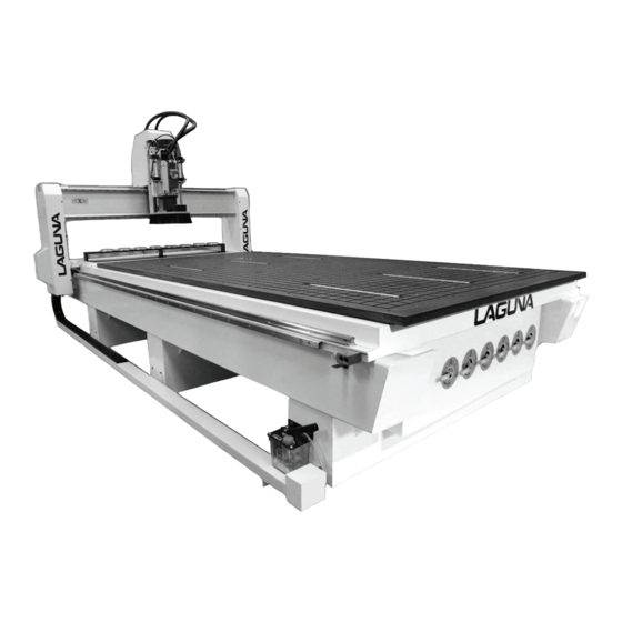
Page 7: Parts Of Your Cnc Router
Parts of the SmartShop ll. Router spindle Gantry Vacuum table Controller/Electrical cabinet Oiler Frame Vacuum switches... - Page 8 Tool changer Caterpillar tracks 1. Bed. The bed of the machine consists of a heavy steel frame with a plastic top that is slotted for the vacuum function. The table has “T-Slots” in the table, which are used to clamp the job or fixtures to the bed. 2.
-
Page 9: What You Receive With Your Cnc Router
5. Controller/Electrical cabinet. The Controller/Electrical cabinet is located on the side of the machine enclosure and houses all the electrical components for controlling and powering the machine. 6. Caterpillar track. The caterpillar track runs along the side of the machine and across the gantry in a trough and carries all the electrical cables and the spindle cooling tubes if water-cooled spindle is fitted. -
Page 10: Unpacking Your Cnc Router
Unpack the machine. To unpack your machine, you will need tin snips, knife and a wrench. 1. Using the tin snips, cut the banding that is securing the machine to the pallet (if fitted). WARNING: EXTREME CAUTION MUST BE USED BECAUSE THE BANDING WILL SPRING AND COULD CAUSE Lock nut INJURY. -
Page 11: Assembly And Setup
Assembly and setup. Air cylinder rods Cleaning the machine. The machine is shipped with the non- painted surfaces protected from rust by a film of grease. The grease must be removed with WD40 or similar, as it attracts sawdust and dirt. The surfaces should then be coated with a 30W oil or wax and any excess removed. - Page 12 Note: When wiring the machine to your electrical system, keep your cable as short as possible, and the cable should not be allowed to run along the floor, as this will cause a trip hazard. The second cable has a female electrical socket for connection to the water pump (if fitted).
- Page 13 Pump Fit electrical plug Pipe connector Fit connector Connecting the water pipes to the pump (if ordered). Note: Never run the water-cooled motor without the cooling being connected, or the motor could be damaged. It is recommended that the pump be run for at least 5 minutes after the motor has been switched off to remove any residual heat.
- Page 14 Fitting the router bit into the router head. Tool holder Collet Nut Note: Before changing or fitting the router bit, always disconnect the power from the machine. 1. Select a router bit and its relevant collet. 2. Fit the collet into the spindle nut. Press the collet into the spindle nut until it snaps into place.
-
Page 15: Machine Operation
Machine Operation. Manual tool release. The tool holder can be released from the spindle manually by pressing the green manual release button. Note: When the green manual release button is pressed, the clamping method is released and the tool will fall out. Place your hand so that the tool holder (not the cutter) is supported. - Page 16 Types of router bits. There are five basic types of router bits: straight, up shear, down shear, combination (also called compression), and form tools (round over, ogee, etc.). 1. Straight Router Bits. These are the standard router bits that are commonly used with handheld routers and are readily available at home centers.
- Page 17 Home switches. There are three switches that determine the home position of the router head. The switches are factory set, and no adjustment should be required. If adjustment is required, contact your service technician prior to conducting any adjustment. X axis home switch Y axis home switch Z axis home switch Y axis home switch...
- Page 18 Optional location pins [optional]. The machine can be supplied with five pneumatic-activated location pins. The pins can be extended or retracted by activating the foot switch. The pins are used as a convenient way to locate a sheet onto the vacuum table. Location pins Foot activation switch Foot activation...
- Page 19 Tool changer and automatic tool contact button. The tool changer consists of a number of tool spindle docking stations (up to a maximum of 8, depending on what was ordered with the machine). The machine knows the location of the docking stations and will retrieve and deposit tool spindles as commanded by the program that it is running.
- Page 20 Control panel. Emergency stop button Electrical On/Off switch Display Vacuum On/Off switch USB socket Spindle frequency display The control panel houses the main interface to the machine. 1. Display. 2. Vacuum On/Off switch. This turns the vacuum on and off. 3.
- Page 21 The router head will move to the home position on the table. Using the vacuum table. Note. The better the vacuum that is created, the more secure the parts will be held in place. Follow the below instructions to obtain optimum results. The vacuum table has 6 zones and you can set the configuration to suite the type of work that you will be producing.
- Page 22 It is recommended that you initially create 3 zones, each one completely across the table. You can change the configuration at a later stage. Start point foam rubber Inserting foam rubber gasket gasket turned in Gasket turned in Cutting end of foam rubber gasket Final finished joint Note: Do not stretch the foam rubber...
- Page 23 Spoil board preparation. When you purchase your MDF spoil board, it should be no thinner than 3/4 inch. Contrary to what you might think, the thicker the MDF, the better the suction that is created. It is not recommended that your spoil board be thicker than 1 inch. The MDF that you purchase will not be flat, and the machine will need to cut it to make it accurate.
- Page 24 board. Ensure that the job has no large burrs on the edges, as this will also reduce the vacuum. In general, keeping everything clean is the key to achieving good, repeatable results. Precautions regarding spoil boards. The spoil board is porous and will absorb moisture. As moisture is absorbed, the dimensions of the board will change.
- Page 25 Gasket turned in Gasket turned in Cutting end of foam rubber gasket Final finished joint Note: Do not stretch the foam rubber Suggested zone configuration gasket while you are fitting it into the groove in the vacuum table. Vacuum table T slots. The vacuum table has T slots to enable fixtures and jobs to be clamped directly to the table.
- Page 26 Fitting the job to the table using the T slots. You may find it convenient to clamp the job to the spoil board with the table clamps. This attachment method can only be used if the outside edges are not being machined. When using the clamps, place a piece of packing under the jacking bolt to protect the bed of the machine.
- Page 27 Membrane Button Descriptions. Alarms. This is a page jump to the first Alarm Screen. Tools. This is a page jump to the first Tool Screen. Start. This button is for starting the program shown in the active Program screen. Hold. This button is used to pause a running program.
- Page 28 SCREEN OVERVIEW.
- Page 29 RUN screen. 1) Homing the machine is the first step every time power is applied. No functions or actions can occur until homing is complete and successful. 2) (Active Program) field shows the current program loaded for run. 3) (Feed Rate) and (Spindle RPM) indicate the programmed rate and speed. 4) (Start at Tool) allows the operator to start a program from a specific tool in a multiple tool program.
- Page 30 RUN2 screen. NOTE: Green numbers in a field indicate an Input field. Press the green number, and a 10-key numerical entry will pop up for entry of the required value. 1) (SET TOOL NO.) This field is used for Instructing the control which tool you manually inserted.
- Page 31 RUN_OVERRIDES screen. The green numbers are fields that can be used for entering a percentage above and below the programmed rates of feed and speed. The red numbered fields show the current rates of feed and speed. The field (RAPID) is used to restrict the machines feed rate by a percentage when a G0 (Rapid Move) is called in a program.
- Page 32 Manual Screen, 1 (Jog and manual spindle control). 1) (CONT. JOG) When pressed, selects a continuous jog mode based on the percentage of full speed chosen under (JOG SPEED). 2) (STEP JOG) When pressed, selects a step jog mode based on the resolution chosen under (STEP SIZE).
- Page 33 Manual 2 Screen. 1) This screen is used for MIDI functions; this is when an operator needs to run a single line of G code at a time. This can do manual tool changes and move any axis to a specific location in the table. Press on the pink command window, and an alpha-numeric pad will pop up for MIDI string entry.
- Page 34 MANUAL3 SCREEN. 1) The top three fields are for setting the Home speeds, from left to right is X, Y, and Z. 2) (SPINDLE DELAY) is the time the program waits for the spindle to become at speed before cutting begins. 3) (X, Y SPEED LIMIT) is the top speed the controller will rapid at when 100% of feed rate is required.
- Page 35 PROGRAM screen. 1) (Active Program) field displays the current program selection. 2) (ACCESS USB) Opens the inserted USB with stored programs. 3) (ACCESS CF CARD) Opens the list of stored programs on the controllers CF card. 4) (COPY) Button moves a program from either the network or the USB to the CF card on the controller.
- Page 36 COORD’S screen. 1) (Machine Coords) is a drop-down menu to select which dimension set is shown in the X, Y, Z, and A axis DROs. The displayed references are for Machine Coordinates, Zero Point Offset (G54), and relative coordinates. 2) (RESET RELATIVE) is a built-in tape measure. By pressing the RESET REATIVE button, you will zero the X- and Y-axis DRO under relative coordinates display.
- Page 37 COORDS2 Screen. 1) This screen is used for exporting all user and factory machine settings in a machine settings .xml file for backup. This is needed if the flash card (operating system) is replaced or upgraded. Simply insert a USB memory stick and press export. A file called “machine settings”...
- Page 38 TOOLS Screen. This screen is used to set up the tool rack by picking up each tool and performing a tool touch-off routine to measure the length for the controller to reference during a program run. 1) The green drop-down menu is used to select a tool for touch-off or to access and modify numbers within the tool table for a specific tool.
- Page 39 Tools 2 screen. NOTE: Only one field on this page pertains to daily operation, (Z spoil). All other fields are for setup and technical support of the controller and will be covered in the advanced section of the manual. 1) (Z spoil) is a user field that is required when using a spoil board to tell the tool table the actual position of Z Zero of each tool.
- Page 40 COORD’S 3 Screen (coord’s set-up). 1) The left side fields are for setting the positive and negative limits of each axis’s travel. 2) The right side of the screen is used to set up a home network for file transfers and remote control via VNC from another computer on the network.
- Page 41 Alarm Screen 1 and 2. Note: Whenever something is wrong with the machine or the Operator has tried to operate outside the machine’s parameters there will be a message on one of these alarm screens. The first screen represents CNC, System, and Machine faults.
- Page 42 Getting Started. Preparing for sheet processing: 1) Place a 3/4" or 1"-thick MDF spoil board with sealed edges (either edge band or seal with a rubbing wax) centered on your table. 2) Insert a small tool into the spindle manually. 3) Press the (MAN) membrane switch to access the manual control screen.
- Page 43 9) With the spindle over the front left corner of the spoil board and (G54) selected, press (Teach ZPO) (zero point offset) to select the front left of the spoil board as the work offset (X and Y Zero)(origin) for your software’s starting point when running code.
- Page 44 15) While on this screen, please verify there is a Zero in the field for (ZSPOIL) so that the tool touch-off is not adjusted incorrectly. 16) Press the (MAN) membrane switch to access the manual control screen. 17) Turn on the vacuum pump in order to draw the spoil board flat to the machine’s table.
- Page 45 TOOL TOUCH-OFF PROCEEDURE. This is the next step in setting up an Automatic Tool Changing machine once the Spoil board is prepared and in place. 1) Go to the (TOOLS) screen. 2) Select the tool you wish to measure with the drop-down selector in the upper left of the screen.
- Page 46 Ethernet connection. 1. Control panel 2. Network hub 4. Ethernet cable connected to 3. Ethernet cable screen 5. Screen seen from inside of control 6. Ethernet cable connected to cabinet network hub...
- Page 47 Store IP address in safe place 7. Network hub You need FILE ZILLA software to be able to transfer files. Real VNC viewer 4 to view machines on your computer Battery cover removed Control panel battery compartment Control panel back up battery. To replace the control panel has a backup battery.
- Page 48 M code. Sync / Function Async Description Sync Yes Predefined: Programmed Stop Sync Yes Predefined: Optional Stop Sync Yes Predefined: End of Main Program / Subprogram Sync Yes Spindle On Sync Sync Yes Spindle Off Sync Yes Tool Changer - executes subprogram brtc.cnc Sync Sync Yes Dust Hood Up On...
- Page 49 Disable Z-Safe Position Offset and Disengage Sync Slide Drills Sync Yes Rotates rack to empty position (tool in spindle) Sync Yes Extends tool rack Sync Yes Rotates rack to new tool position Sync Yes Retracts rack Sync Yes A Axis free run - MoveVelocity command Sync Yes Stop A Axis Sync...
- Page 50 G code.
- Page 53 Maintenance. As with any machine, to ensure optimal performance, you must conduct regular maintenance. Lubrication. You must regularly (minimum every 12 hours) lubricate the bearing surfaces and the ball screws. Use a thin Lithium spray or a 30wt oil lubricant. Spray daily and wipe off the excess.
- Page 54 Oiling the machine. The machine is provided with a central oiler. Do not over-lubricate the machine, as the excess oil attracts dirt and sawdust. It is recommended that one pump of the oiler once a month will be sufficient to keep your machine lubricated.
- Page 55 Components inside the electrical control box. B& R controller PLC rack Drivers Main Breaker Termination block...
- Page 56 EMI filter [Variable frequency drive] Front electrical panel Main Isolation switch Breaker Fuses 24V power supply 72V p.s.
- Page 57 Troubleshooting. Machine will not start. 1. Check that the start switch is being pressed full in. 2. Check that the red emergency stop switch is fully out. 3. Check that the electrical power cord is plugged into the power outlet. 4.
- Page 58 The controller display shows that the spindle is not rotating and vice versa. 1. Check the wiring for loose or broken wires. 2. The spindle settings on the VFD are incorrect. For technical support contact Laguna Tools at 1-800-234-1976 email Laguna Tools Customer Service at customerservices@lagunatools.com...
-
Page 59: Machine Drawing
Machine drawing. - Page 60 Note: The wiring may vary from the following drawings dependent on the options that you ordered...
- Page 69 Laguna Tools is not responsible for errors or omissions. Specifications subject to change. Machines may be shown with optional accessories. © 2018, Laguna Tools, Inc. LAGUNA® and the LAGUNA Logo® are the registered trademarks of Laguna Tools, Inc. All rights reserved.
Need help?
Do you have a question about the Smartshop II Series and is the answer not in the manual?
Questions and answers