Table of Contents
Advertisement
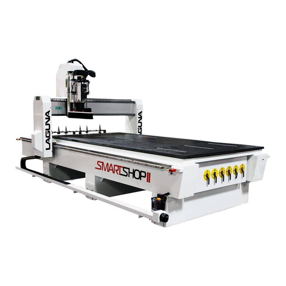
Smartshop II Manual
SmartShop ll 4'x8' - 6 HP Spindle 10HP Vacuum CNC Router
SmartShop ll 4'x8' - 7.5HP Spindle 10HP Vacuum CNC Router
SmartShop ll 5'X10' - 7.5HP spindle CNC Router
SmartShop ll 4'x8' - 11HP HSD Spindle 10HP Vacuum CNC Router w/ATC
SmartShop ll 5'x10' - 11HP HSD Spindle 10HP Vacuum CNC Router
LAGUNA TOOLS
2072 Alton Parkway
Irvine, California 92606
Ph: 800.234.1976
www.lagunatools.com
© 2018, Laguna Tools, Inc. LAGUNA® and the LAGUNA Logo® are the registered trademarks of Laguna Tools, Inc. All rights reserved.
Model No.
MCNC SS2 4X8 6 HP LIQUID COOLED
MCNC SS2 4X8 liquid ATC-0158
MCNC SS2 5X10 Liquid ATC-0158
MCNC SS2 4X8 HSD ATC-0158
MCNC SS2 5X10 HSD ATC-0158
Advertisement
Table of Contents

Subscribe to Our Youtube Channel
Related Manuals for Laguna Tools Smartshop II

Summary of Contents for Laguna Tools Smartshop II
- Page 1 MCNC SS2 5X10 Liquid ATC-0158 Irvine, California 92606 MCNC SS2 4X8 HSD ATC-0158 Ph: 800.234.1976 MCNC SS2 5X10 HSD ATC-0158 www.lagunatools.com © 2018, Laguna Tools, Inc. LAGUNA® and the LAGUNA Logo® are the registered trademarks of Laguna Tools, Inc. All rights reserved.
-
Page 3: Table Of Contents
Table of Contents Safety Rules ..................Limited Warranty ................Noise Emission/Receiving the Machine ..........Machine Specifications ..............Introduction to CNC Machines ............9-10 Additional Accessories ..............Machine Installation ................Assembly & Setup ................Electrical Connections ............... Compressed Air Connection .............. Connecting Vacuum Pump .............. -
Page 4: Safety Rules
Safety Rules As with all machinery, there are certain hazards involved with the operation and use. Using it with caution will considerably lessen the possibility of personal injury. However, if normal safety precautions are overlooked or ignored, personal injury to the operator may result. If you have any questions relative to the installation and operation, do not use the equipment until you have contacted your supplying distributor. -
Page 5: Limited Warranty
Machines sold through dealers must be registered with Laguna Tools within 30 days of purchase to be covered by this warranty. Laguna Tools guarantees all new machines and accessories sold to be free of manufacturers’... -
Page 6: Noise Emission/Receiving The Machine
All damage must be noted on the delivery documents and signed by you and the delivery driver. You must then contact the seller, Laguna Tools, within 24 hours. It is probable that you will find sawdust on your SmartShop II. Laguna endeavors to test all machines... -
Page 7: Machine Specifications
Machine Specifications Motor Drive Delta brand VFD-E variable frequency drive Spindle 11 HP HSD (Italian) Electrospindle ISO-30 (ATC), Ceramic Spindle Bearings Spindle RPM 6,000 - 24,000 RPM Controller Laguna “Touch” Series CNC Controller. Machine features the networking, connectivity and online troubleshooting. Runs industry standard G-Code. - Page 8 25mm heavy-duty HiWin HG Series linear bearings and rails on all axes Helical Rack-and-pinion drives on “X” and “Y” axes and precision-ground ball screw drive on “Z” axis Gantry is driven on each end (two “helical” rack-and-pinion drives on “Y” axis) Limit switches Solid State...
-
Page 9: Introduction To Cnc Machines
It is possible to reduce the amount of different machines in the shop as the CNC will perform multiple functions and is a must for cabinetmakers and serious woodworkers. Laguna SmartShop II Machine Parts Electro-Spindle Tool Rack ATC Gantry... - Page 10 Each of the stations includes a ISO-30 gripper assembly, and station positions are controlled the Laguna Touch CNC controller. Additional Instructions for the use of the Laguna SmartShop II CNC Like all machines, there is danger associated with the machine. Injury can be caused by lack of knowledge or familiarity.
-
Page 11: Additional Accessories
Additional Accessories that are included with the Machine Clamps Cutters and Collets Memory Stick Dust Hose Clamps Tool Holder Wrenches Note: The quantity of collets, cutters and clamps will vary from that shown, depending on your order. -
Page 12: Machine Installation
Machine Installation Machine Location Before unpacking the machine, select the area where the machine will be installed. There are no hard-and-fast rules for its location, but below are a few guidelines: 1) There should be an area around the machine suitable for the length of material that will be machined as well as any loading and unloading requirements. -
Page 13: Assembly & Setup
Assembly & Setup Cleaning the Machine The machine is shipped with the non-painted surfaces protected from rust by a film of grease. The grease must be removed with WD40 or similar solvent, as it attracts sawdust and dirt. The surfaces should then be coated with a Teflon lubricant or similar. -
Page 14: Electrical Connections
Electrical Connections There are two electrical connections required. One is the main power cable that is connected to the main power switch in the machine control cabinet. The second power cable is used to connect the machine control cabinet with the vacuum pump. -
Page 15: Compressed Air Connection
It is strongly recommended that 6.5 bar (95 psi) be supplied to the Laguna SmartShop II and that the regulator then be set to 6 bar (85 psi). This will ensure that the machine always has the minimum required air pressure. The input regulator has a moisture trap that must be emptied each day. -
Page 16: Connecting Vacuum Pump
Connecting the Vacuum Pump The machine is provided with a 2-inch hose for connection to the the vacuum pump. The vacuum hose is connected to the manifold located under the table toward the front of the machine. Connect the free end to the vacuum hose to the vacuum pump inlet. Ensure that it is clamped securely. - Page 17 Installing the Router Bit in the Tool Holder Caution: Before changing or fitting the router bit, always disconnect the power to the machine. 1) Select a router bit and its relevant collet. 2) Fit the collet into the spindle nut. Press the collet into the spindle nut until it snaps into place.
-
Page 18: Manual Tool Release
Manual Tool Release The tool holder can be released from the spindle manually by pressing the green manual release button near the Electro-Spindle. Note. When the green manual release button is pressed, the clamping method is released and the tool will fall out. Place your hand so that the tool holder (not the cutter) is supported. -
Page 19: Selecting Correct Router Bit
Selecting the Correct Router Bit There are five basic types of router bits: straight, up shear, down shear, combination (also called compression) and form tools (round over, ogee, etc.). Each type of bit has a specific application for use. Straight Router Bits These are the standard router bits that are commonly used with handheld routers and are readily available at home centers. - Page 20 Combination (Compression) Router Bits These bits combine the advantages of both up shear and down shear designs. The top section of the tool is down shear to prevent chipping the top surface of the material, and the lower part of the bit is up shear to prevent chipping the bottom surface of the material.
-
Page 21: Working With Vacuum Tables And Spoil Boards
Working With Vacuum Tables and Spoil Boards The more effective the vacuum table setup, the more secure the parts will be held in place. Follow the instructions below to obtain optimum results. The vacuum table has six (6) zones that can be used to configure the vacuum supply depending on the type of application. - Page 22 Functions of the Spoil Board 1) To protect the vacuum table from damage. The cutter extends only a few thousandths of an inch past the material thickness. Without the spoil board, the cutters could damage the surface of the vacuum table. 2) To transfer the vacuum from the table to the job.
- Page 23 6) Fly cut the surface of the spoil board, removing approximately 0.060" to insure that the compressed surface of the material is removed. 7) Once the material surface is machined, turn off the vacuum pump, turn the spoil board over and repeat the process for the other side. (Remember to ensure that the table and spoil board are clean.) Spoil Board Use Each time a new job is machined, there may be shallow cuts into the spoil...
- Page 24 Vacuum Table T-Slots The vacuum table has T-slot mounting devices incorporated into the tables to enable fixtures and material blanks to be clamped directly to the table. Clamps are provided, but the table must be protected with a backer when using jacking bolts. If the jacking bolts come in contact with the composite or aluminium of the table, the materials could be damaged.
- Page 25 The Laguna Touch CNC Controller The Laguna Touch CNC controller was designed to be easy-to-learn and easy-to operate. There are ten (10) buttons that are carefully spaced (five on each side of the touch screen) for ease of use. Screen selection on the touch screen unit are determined by the button selection.
- Page 26 SMART SHOP II REV,1 10-31-2012...
- Page 27 SCREEN OVERVIEWS RUN screen Homing the machine is the first step every time power is applied. No functions or actions can occur until homing is complete and successful. 1) Active Program field shows the current program loaded for run. 2) Feed Rate and Spindle RPM indicate the programmed rate and speed. 3) Start at Tool allows the operator to start a program from a specific tool in a multiple-tool program.
- Page 28 RUN/OVERRIDES screen The Numbers shown in Green on the machine control screen are fields that can be used for entering a percentage above and below the programmed rates of feed and speed. The Numbers shown in Red on the machine control screen are fields that show the current rates of feed and speed.
- Page 29 MANUAL/Screen 1 (Jog and Manual Spindle Control) 1) CONT. JOG-When pressed, selects a continuous Jog Mode based on the percentage of full speed chosen under JOG SPEED. 2) STEP JOG -When pressed, selects a step jog mode based on the resolution chosen under STEP SIZE.
- Page 30 MANUAL/Screen 2 This screen is used for MDI (Manual Data Input) functions; MDI is used when an operator needs to run a single line of G-code at a time. For example, MDI can be used to perform manual tool changes and move any axis to a specific location in the table.
- Page 31 MANUAL/Screen 3 The top three fields are for setting the Home speeds; from left to right: X, Y and Z. 1) SPINDLE DELAY is the time the program waits for the spindle to come to speed before cutting begins. 2) X, Y SPEED LIMIT is the top speed the controller will rapid at when 100% of feed rate is required.
- Page 32 PROGRAM screen Active Program field displays the current program selection. ACCESS USB opens the inserted USB with stored programs. ACCESS CF CARD opens the list of stored programs on the controllers CF card. COPY button moves a program from either the network or the USB to the CF card on the controller.
- Page 33 TOOLS screen This screen is used to setup the tool rack by picking up each tool and performing a tool touch-off routine to measure the length for the controller to reference during a program run. 1) The green drop-down menu is used to select a tool for touch-off or to access and modify numbers within the tool table for a specific tool.
- Page 34 TOOLS/Screen 2 NOTE: Only one field on this page pertains to daily operation, ZSPOIL. All other fields are for setup and technical support of the controller and will be covered in the advanced section of the manual. ZSPOIL is a user field that is required when using a spoil board to tell the tool table the actual position of Z Zero of each tool.
- Page 35 TOOLS/COORDS Screen 1 Machine Coords is a drop-down menu to select which dimension set is shown in the X, Y, Z and A axis DROs. The displayed references are for Machine Coordinates, Zero Point Offset (G54) and relative coordinates. 1) RESET RELATIVE is a built-in tape measure. By pressing the RESET REATIVE button you will zero the X and Y axis DRO under relative coordinates display.
- Page 36 TOOLS/COORDS Screen 2 This screen is used for exporting all user and factory machine settings into a “machine settings.xml” file for backup. This is needed if the Compact Flash card (operating system) is replaced or upgraded. Simply insert a USB memory stick and press export; a file called machine settings will be generated.
- Page 37 TOOLS/COORDS Screen 3 (Coords Setup) The left-side fields are for setting the positive and negative limits of each axis’s travel. The right side of the screen is used to setup a home network for file transfers and remote control via VNC from another computer on the network.
- Page 38 ALARM Screens. ALARM Screen 2 (Represents Axis Errors) If the error cannot be reset with the CLEAR ALL button, contact Laguna Tools Customer Service department for assistance.
- Page 39 SMART SHOP II DRILL BLOCK REV,1 10-31-2012...
-
Page 40: Getting Started
Getting Started Preparing for sheet processing, Setting the Zero Point Offset 1) Place a ¾" or 1" thick MDF spoil board with sealed edges (either edge band or seal with a rubbing wax), centered on the vacuum table. 2) Insert a small tool (VBit if available) into the spindle manually. 3) Press the MAN membrane switch to access the Manual control screen. - Page 41 9) With the spindle over the front left corner of the spoil board and G54 selected, press Teach ZPO, to select the front left of the spoil board as the work offset (X and Y Zero) (origin) for your software’s starting point when running code.
- Page 42 Select “Tool 8” Enter “8” 15) Using the drop down menu select tool 8 and input the number 8 in the green field, Set Tool In Spindle. This will set up the system for touching off the spoil board cutter to Z zero later in these instructions. 16) Press NEXT to access the second tooling screen.
- Page 43 18) Press the MAN membrane switch to access the Manual control screen. 19) Turn on the vacuum pump in order draw the spoil board flat to the machine's table. 20) Using the Jog functions, lower the Z axis to the top of the spoil board until it just touches the top of the MDF sheet.
-
Page 44: Tool Touch-Off Procedure
TOOL TOUCH-OFF PROCEDURE This is the next step in setting up an Automatic Tool Changing (ATC) machine once the spoil board is prepared and in place. 1) Go to the TOOLS screen. 2) Select the tool you wish to measure with the drop-down selector in the upper left of the screen. - Page 45 6) Measure the spoil board and enter the thickness into ZSPOIL field on the Second Tools Screen. 7) HOME the machine to update the spoil board thickness value (ZSPOIL). With the spoil board thickness entered into ZSPOIL Z Zero is now the top of the spoil board and the machine is ready for panel processing.
-
Page 46: Machine Maintenance
Machine Maintenance As with any machine, to ensure optimal performance you must conduct regular maintenance. Daily Checks 1) Clean the machine and lubricate unpainted surfaces with a Teflon lubricant. Wipe off any excess and buff with a dry polishing cloth. This will reduce the likelihood of rust forming. -
Page 47: Troubleshooting
Troubleshooting Machine will not start Check that the start switch is being pressed full in. Check that the red stop switch is fully out. Check that the electrical power cord is plugged into the power outlet. Check that the electrical supply is on (reset the breaker). With the power disconnected from the machine, check the wiring to make sure the plug is correct. - Page 48 B&R G-Code Functions Overview G-Function M S Group Description Rapid interpolation Linear interpolation Circular interpolation - clockwise Circular interpolation - counter clockwise Dwell time in seconds Direct programming of the polar axes in the clockwise direction (starting with V0.207) Direct programming of the polar axes in the counter - clockwise direction (starting with V0.207) Programmed path speed on the tool center point...
- Page 49 G103 CDC: Radius - dependent feed adjustment at convex path sections (starting with V0.201) G104 CDC: Radius - dependent feed adjustment at concave path sections (starting with V0.201) v_jump" Parameter (starting with V0.198) G105 Setting the " a_jump" Parameter (starting with V0.198) G106 Setting the "...
- Page 50 G234 Activation Change without transition lines G235 Activation Change with transition lines G240 Non - periodic tangential axis (starting with V0.151) G241 Periodic tangential axis (starting with V0.151) G292 Rotate/Shift Coordinate System G300 Chord error monitoring (starting with V0.201) G300 Chord Error Monitoring: Variations for polar coordinate motor (starting with V0.201) G320 Workspace Boundaries De nition and Monitoring Activation...
- Page 51 Laguna Tools is not responsible for errors or omissions. Specifications subject to change. Machines may be shown with optional accessories. © 2018, Laguna Tools, Inc. LAGUNA® and the LAGUNA Logo® are the registered trademarks of Laguna Tools, Inc. All rights reserved.
Need help?
Do you have a question about the Smartshop II and is the answer not in the manual?
Questions and answers
What are the other fields on page 34 of the manual?
Page 34 of the Laguna Tools Smartshop II manual lists fields used for exporting all user and factory machine settings into a "machine settings.xml" file for backup. It also includes fields for setting the positive and negative limits of each axis’s travel on the left side and for setting up a home network for file transfers and remote control via VNC on the right side.
This answer is automatically generated