Table of Contents
Advertisement
Quick Links
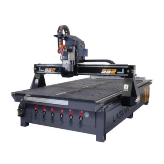
SmartShop SS2 (SS II) Manual 2021
Basic Operations-Main Screen Set-up, Set-up Menus, Machine Settings,
CNC Tool Data, Delivery Protocols, Warranties, Packaging/RMA
Procedures.
• SmartShop II 4'x4'-6 HP Spindle 10HP Vacuum CNC Router
• SmartShop ll 4'x8' - 6 HP Spindle 10HP Vacuum CNC Router
• SmartShop ll 4'x8' - 7.5HP Spindle 10HP Vacuum CNC Router
• SmartShop ll 5'X10' - 7.5HP spindle CNC Router
• SmartShop ll 4'x8' - 11HP HSD Spindle 10HP Vacuum CNC Router w/ATC
• SmartShop ll 5'x10' - 11HP HSD Spindle 10HP Vacuum CNC Router
Laguna Tools
744 Refuge Way
Grand Prairie, TX. 75050
Direct Phone #: (800) 234-1976
Warranty Repair Information: (800) 332-4094
1
Advertisement
Table of Contents

Related Manuals for Laguna Tools SmartShop SS2


Summary of Contents for Laguna Tools SmartShop SS2
- Page 1 SmartShop SS2 (SS II) Manual 2021 Basic Operations-Main Screen Set-up, Set-up Menus, Machine Settings, CNC Tool Data, Delivery Protocols, Warranties, Packaging/RMA Procedures. • SmartShop II 4’x4’-6 HP Spindle 10HP Vacuum CNC Router • SmartShop ll 4'x8' - 6 HP Spindle 10HP Vacuum CNC Router •...
-
Page 2: Table Of Contents
Working With Vacuum Tables and Spoil Boards- Vacuum Table T-Slots & Automatic Tool Changer (ATC)- Delivery Protocol- Parts & Service- Laguna Tools Warranty- Laguna Tools Packaging/RMA Procedures- Laguna Tools Packaging/Laguna Tools RMA Example- Laguna Tools Packaging/Laguna Tools BILL of LADING Example-... -
Page 3: Safety Rules
Safety Rules- As with all machinery, there are certain hazards involved with the operation and use. Using it with caution will considerably lessen the possibility of personal injury. However, if normal safety precautions are overlooked or ignored, personal injury to the operator may result. If you have any questions relative to the installation and operation, do not use the equipment until you have contacted your supplying distributor. -
Page 4: Smartshop Ss2 Machine Specifications
SmartShop SS2 Machine Specifications- Machine Specifications SS2 Motor Drive+A2:A39 Delta brand VFD-E variable frequency drive. Spindle 11 HP HSD (Italian) Electrospindle ISO-30 (ATC), Ceramic Spindle Bearings. Spindle RPM 6,000 - 24,000 RPM Laguna “Touch” Series CNC Controller. Machine features the Networking, Connectivity and online Troubleshooting. - Page 5 SmartShop SS2 Machine Specifications- Machine Specifications SS2 49.0" x 73.0" x 8.0" (4' x 4' Model) 49.0" x 97.0" x 8.0" (4' x 8' Model) Work Envelope 61.0" x 121.0" x 8.0" (5' x 10' Model) 61.0" x 145.0" x 8.0" (5' x 12' Model)
-
Page 6: Introduction To Cnc Machines
Introduction to CNC Machines- Caterpillar Track (On Opposite Side). Electro- Spindle ATC Tool Rack Gantry Tool Clips Bed or Machine Table Vacuum Control Valves Caterpillar Track... -
Page 7: Introduction To Cnc Machines- Glossary & Definitions
Introduction to CNC Machines- Glossary & Definitions: Machine Table: The bed of the machine consists of a heavy steel all-welded frame with a composite worktable that is machined for use with a vacuum pump. The table includes T-slots (and clamps) for special fixturing. The T-slots are used to clamp the job or fixtures to the bed. -
Page 8: Accessories, Machine Location, Unpacking & Installation
Accessories, Machine Location, Unpacking & Installation- List of Additional Accessories: Clamps Cutters & Collets Memory Stick Dust Hose Clamps Tool Holders Wrenches Machine Location, Unpacking & Installation- Machine Location & Guidelines: Before unpacking the machine, select the area where the machine will be installed. 1) There should be an area around the machine suitable for the length of material that will be machined as well as any loading and unloading requirements. - Page 9 Machine Location, Unpacking & Installation (Cont’d.)- Unpacking the Machine: Unpacking the machine will require tin snips (to cut banding), a knife and an adjustable wrench. Follow the steps below: 1) Using the tin snips, cut the banding that is securing the machine to the pallet (if fitted). 2) WARNING: EXTREME CAUTION MUST BE USED BECAUSE THE BANDING CAN SPRING AND COULD CAUSE INJURY.
- Page 10 Machine Location, Unpacking & Installation (Cont’d.)- 1.) Using Leveling Feet, Support and Level SS2 CNC Machine. 2.) SAFETY-Verify your shop/building has proper electrical supply. For confirmation on this, call customer service (1-800-234-1976) for diagrams verifying proper voltage & amperage requirements. 3.) Have a Certified Electrician wire from building breaker into control box (Does not need to hook up L1, L2, and L3, but they must run the wire into the box.)
- Page 11 Machine Location, Unpacking & Installation (Cont’d.)- 4.) Have a Certified Electrician wire from contactor to vacuum. (Run wires to vacuum and into box, we can wire once the wires are inside to the contactor. Vacuum has a Legend-Plate, electrician must decide wire size). 5.) Hook up clean, dry air to compressor on rear of machine underneath tool rack.
- Page 12 Machine Location, Unpacking & Installation (Cont’d.)- The machine is supplied with an air regulator. The input air regulator regulates the air pressure that is supplied to the machine. You will require an air supply that can deliver a constant minimum pressure of 85 psi. The input air regulator will need to be adjusted to 85 psi-90 psi once you have connected your air supply to the machine.
- Page 13 Machine Location, Unpacking & Installation (Cont’d.)- 6.) Verify all items that were purchased and are on the sales order were sent and included. Verify there is a dust hood on the spindle. (If any items are missing, call customer service (1-800-234-1976 for verification on missing items so they may be sent out) 7.) If providing own tooling, verify all proper tooling is available and readily available.
-
Page 14: Fitting The Dust Hose
Fitting the Dust Hose- 1. Fit the dust shroud to the two air cylinder rods and clamp in position with the clamping nuts. 2. Fit a 4-inch (not supplied) dust hose to the dust shroud and secure with the clamp. Ensure that it is tight;... -
Page 15: Connecting The Vacuum Pump
Connecting the Vacuum Pump- The machine is provided with a 2-inch hose for connection to the vacuum pump. The vacuum hose is connected to the manifold located under the table toward the front of the machine. Connect the free end to the vacuum hose to the vacuum pump inlet. Ensure that it is clamped securely. -
Page 16: Installing Router Bit
Installing Router Bit- Installing the Router Bit in the Tool Holder Caution: Before changing or fitting the router bit, always disconnect the power to the machine. 1) Select a router bit and its relevant collet. 2) Fit the collet into the spindle nut. Press the collet into the spindle nut until it snaps into place. Note: The router bit must not be fitted into the collet until the collet has been fitted into the spindle nut. - Page 17 Manual Tool Release- The tool holder can be released from the spindle manually by pressing the “Green Manual Release Button” near the Electro- Spindle. Note. When the “Green Manual Release Button” is pressed, the clamping is released and the tool will fall out. Place your hand so that the tool holder (not the cutter) is supported.
-
Page 18: Selecting The Correct Router Bit
Selecting the Correct Router Bit- Straight Router Bits: These are the standard router bits that are commonly used with handheld routers and are readily available at home centers. They will work but will generally not produce the edge finishes that are available with the spiral designed router bits. - Page 19 Selecting the Correct Router Bit (Cont’d.)- Ball Nose Router Bits: are a variation of the up shear bit design but have radiuses on the ends. These bits are typically used for 3D surfacing applications. Down Shear Router Bits: These bits are similar to the up shear but with an opposite spiral that actually tends to pack the chips into the kerf.
- Page 20 Selecting the Correct Router Bit (Cont’d.)- Combination (Compression) Router Bits: These bits combine the advantages of both up shear and down shear designs. The top section of the tool is down shear to prevent chipping the top surface of the material, and the lower part of the bit is up shear to prevent chipping the bottom surface of the material.
- Page 21 Selecting the Correct Router Bit (Cont’d.)- Form Router Bits: Form Router Bits typically are available in standard profiles such as round over, ogee, cove, etc. Router bits that have a shape associated with them would be classified with this group.
- Page 22 Working With Vacuum Tables and Spoil Boards- The more effective the vacuum table setup, the more secure the parts will be held in place. Follow the instructions below to obtain optimum results. The vacuum table has six (6) zones that can be used to configure the vacuum supply depending on the type of application.
- Page 23 Working With Vacuum Tables and Spoil Boards (Cont’d.)- The table has vacuum ports for each zone that extract the air and generate the vacuum. The table also has grooves to ensure that the air is extracted evenly across the zones. Each zone is controlled by a valve located at the front of the machine.
- Page 24 Working With Vacuum Tables and Spoil Boards (Cont’d.)- Spoil Board Material and Precautions For machining parts from panel materials (cabinets, fixtures, case goods, etc.) a technology referred to as “Flow-Through” fixturing is employed. A sheet of porous material (usually MDF [Medium-Density Fiberboard]) is placed on top of the vacuum table.
- Page 25 Working With Vacuum Tables and Spoil Boards (Cont’d.)- The purpose is to limit vacuum infiltration through grooves in the spoil board. This also allows the processing of various nests without any setup time on the machine. This technology is the basis for Nested-Based Manufacturing (NBM)-Nested-based manufacturing refers to a system used to efficiently produce groups of rectangular and non-symmetrical parts from flat material, such as composite and solid wood panels or plastic sheets.
- Page 26 Working With Vacuum Tables and Spoil Boards (Cont’d.)- Functions of the Spoil Board- 1)To protect the vacuum table from damage. The cutter extends only a few thousandths of an inch past the material thickness. Without the spoil board, the cutters could damage the surface of the vacuum table. 2)To transfer the vacuum from the table to the job.
- Page 27 Working With Vacuum Tables and Spoil Boards (Cont’d.)- The spoil board (MDF) edges are also very porous, and sealing them can improve the part holding ability. ***Hard Candle Wax-is an excellent product for sealing the spoil board edges because it contains no water and is very easy to apply***.
-
Page 28: Working With Vacuum Tables And Spoil Boards
Working With Vacuum Tables and Spoil Boards (Cont’d.)- Use the following Procedure for preparing the Spoil Board: 1) Cut the spoil board to the size of the table of the machine, if necessary. 2) Apply gasketing (The action of fitting or sealing with a gasket) to the outermost vacuum grooves on the table surface. - Page 29 Working With Vacuum Tables and Spoil Boards (Cont’d.)- Spoil Board Use Each time a new job is machined, there may be shallow cuts into the spoil board in the areas that the cutter passes through the material. Prior to placing a sheet of material on the spoil board, clean with a hand-held blower or vacuum cleaner.
- Page 30 Working With Vacuum Tables and Spoil Boards (Cont’d.)- There are, however, exceptions- 1) It is a good practice to keep material on the top surface of the spoil board overnight to prevent warpage due to uneven moisture absorption by the material. 2) Once a spoil board has been used and has kerf cuts that resulted from machining parts, it is a good idea to fly cut the surface again.
-
Page 31: Vacuum Table T-Slots & Automatic Tool Changer (Atc)
Vacuum Table T-Slots & Automatic Tool Changer (ATC)- The vacuum table has T-slot mounting devices incorporated into the tables to enable fixtures and material blanks to be clamped directly to the table. Clamps are provided, but the table must be protected with a backer when using jacking bolts. If the jacking bolts come in contact with the composite or aluminum of the table, the materials could be damaged. - Page 32 Vacuum Table T-Slots & Automatic Tool Changer (ATC) Cont’d.- ATC Bracket & Tool Automatic Tool Changer-ATC Tool Touch Off-TTO The Automatic Tool Touch-Off system (described later in this manual) is used to measure the Automatic Tool Changer (ATC) tool lengths automatically. The Automatic Tool Changer consists of a group of tool holder grippers mounted to a rigid bar.
- Page 33 Safety Rules- Safety Rules As with all machinery, there are certain hazards involved with the operation and use. Using it with caution will considerably lessen the possibility of personal injury. However, if normal safety precautions are overlooked or ignored, personal injury to the operator may result. If you have any questions relative to the installation and operation, do not use the equipment until you have contacted your supplying distributor.
-
Page 34: Delivery Protocol
Delivery Protocol- • Most large machinery will be delivering on a tractor trailer 48'-53' long. Please notify Sales Representative with any Delivery Restrictions. • Customer is required to have a forklift (6000lb. or larger is recommended) with 72" forks or fork extensions and operator. •... -
Page 35: Parts & Service
Parts & Service... -
Page 36: Laguna Tools Warranty
Machines sold through dealers must be registered with Laguna Tools within 30 days of purchase to be covered by this warranty. Laguna Tools guarantees all new machine sold to be free of manufacturers’ defective workmanship, parts and materials. We will repair or replace, without charge, any parts determined by Laguna Tools, Inc. - Page 37 Technical support to install replacement parts is primarily provided by phone, fax, e-mail or Laguna Tools Customer Support Website. The labor required to install replacement parts is the responsibility of the user. Laguna Tools is not responsible for damage or loss caused by a freight company or other circumstances not in our control.
- Page 38 Laguna Tools Warranty-...
- Page 39 Support Website. The labor required to install replacement parts is the responsibility of the user. Laguna Tools is not responsible for damage or loss caused by a freight company or other circumstances not in our control. All claims for loss or damaged goods must be notified to Laguna Tools within twenty-four hours of delivery.
-
Page 40: Laguna Tools Packaging/Rma Procedures
Laguna Tools Packaging/RMA Procedures- Dealer Machinery Warranty **Any machines returned to Laguna Tools must be returned with packaging in the same manner in which it was received. If a part or blade is being returned it must have adequate packaging to ensure no damage is received during shipping. In the... -
Page 41: Laguna Tools Packaging/Laguna Tools Rma Example
Laguna Tools Packaging/Laguna Tools RMA Example- RMA #... -
Page 42: Laguna Tools Packaging/Laguna Tools Bill Of Lading Example
Laguna Tools Packaging/Laguna Tools BILL of LADING Example-...
Need help?
Do you have a question about the SmartShop SS2 and is the answer not in the manual?
Questions and answers