Kärcher SCW 2.4/25 G Service Manual
Surface cleaner/pressure washer
Hide thumbs
Also See for SCW 2.4/25 G:
- Manual (140 pages) ,
- Operator's manual (86 pages) ,
- Owner's manual (130 pages)
Table of Contents
Advertisement
Quick Links
Advertisement
Table of Contents

Subscribe to Our Youtube Channel
Related Manuals for Kärcher SCW 2.4/25 G


Summary of Contents for Kärcher SCW 2.4/25 G
- Page 1 SCW 2.4/25G Service Manual English 9.808-136.0 Rev. 00 (09/18)
-
Page 2: Table Of Contents
Contents Preface Safety instruc$ons Hazard levels Descrip$on in this service manual Service Groups Technical Features Intended use Field of applica on Safety installa ons Safety catch Unloader / bypass valve Thermal relief valve Symbols on the machine Type plate Flow pa"ern Overview of the appliance 8-10 Callouts SCW 2.4/25G... - Page 3 Inspec ng piston guide oil seals for oil leak Inspec ng trigger gun for leak Inspec ng spray bar trigger for leak Technical documenta$on Technical specifica ons SCW 2.4/25 G 41-42 Tools required Torque specifica ons English 9.808-136.0 Rev. 00 (09/18)
-
Page 4: Preface
Preface Good service work requires extensive and prac ce-oriented If you should require addi onal assistance, have correc ons or training as well as well-structured training materials. Hence we ques ons regarding this document, please do not hesitate offer regular basic, advanced and expert training programs contac ng us at: www.karcher.com/us and click on customer covering the en re product range for all cer fied distributor feedback to enter any info you may have for us or you can also... -
Page 5: Descrip$On In This Service Manual
Flat surface cleaning—I.E. Business entrances, parking lots, tennis courts, pool decks and sidewalks Field of applica$on This service manual describes the following appliance: Appliance type Appliance no. Operating instructions Spare parts list SCW 2.4/25 G 1.107-380.0 9.802-898.0 9.802-898.0 English 9.808-136.0 Rev. 00 (09/18) -
Page 6: Safety Installa Ons
Safety installa$ons Safety devices serve to protect the user and must not be Observe safety information in the chapters! rendered in operational or their functions bypassed. Safety catch The safety catch on the trigger gun prevents the appli- ance from being switched on unintentionally. Unloader / bypass valve If the hand trigger bar or trigger gun is closed, the unload- The unloader / bypass valve is set by the manufacturer... -
Page 7: Flow Pa"Ern
Flow pa1ern 1 Water filter 2 High-pressure pump 3 Unloader valve 4 Thermal relief valve English 9.808-136.0 Rev. 00 (09/18) -
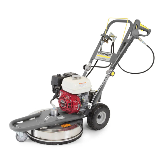
Page 8: Overview Of The Appliance
Overview of the appliance Call outs SCW 2.4/25G English 9.808-136.0 Rev. 00 (09/18) - Page 9 English 9.808-136.0 Rev. 00 (09/18)
- Page 10 1 Trigger bar 13 Tire, flat free 2 Pump, pressure 14 Knob, handle adjustment 3 Tank, gas 15 Unloader / by-pass valve 4 Filter, air 16 Inlet, fresh water 5 Caster, front 17 Starter, manual, recoil 6 Brush skirt 18 Spray bar 7 Surface cleaner 19 Nozzle 8 Dip s ck, oil, engine...
-
Page 11: Pump Overview
Pump overview 5.2.1 Pump head overview 1 Outlet ports 2 Outlet / high pressure valve caps 3 Inlet ports 4 Inlet / low pressure valve caps 5 Manifold 6 Manifold bolt 5.2.2 Pump head cross-sec$on overview 1 Outlet high pressure check valve 2 Outlet / high pressure valve cap 3 Outlet port 4 High pressure packing... -
Page 12: Pump Cross Sec On Overview
5.2.3 Pump cross-sec$on overview 1 Dips ck, oil 6 Wrist pin 2 Oil seal 7 Connec ng rod 3 High pressure packing 8 bearing, cranksha? 4 Low pressure packing 9 Cranksha? 5 Piston guide English 9.808-136.0 Rev. 00 (09/18) -
Page 13: Unloader / Bypass Valve Overview
Unloader / Bypass valve overview 1 Knob, adjustment, by-pass pressure 2 Spring, pressure 3 Nut, lock 4 Piston, stem 5 Outlet port 6 By-pass port 7 Inlet port 8 Banjo bolt, inlet, pump 9 Banjo bolt, outlet, pump 10 Ball subassembly Filter, high pressure overview 1 Housing, nozzle filter, 1/4 NPT-F 2 Retainer, filter... -
Page 14: Swivel, High Pressure Overview
Swivel, High pressure overview 1 Grease nipple 2 Rotor sha? 3 Swivel housing 4 Upper bearing 5 Lower bearing The Surface Cleaner Unit high pressure swivel will “weep” wa- ter from underneath the cover. This weeping is normal for this swivel. -
Page 15: Service Group
Service group Scheduled maintenance chart MAINTENANCE ITEM ACTION TIME FRAME REFERENCE SECTION 6.4.1 Inspect Daily 6.4.2 First 5 hrs. ENGINE OIL Every 50 hrs. or every 6 Change months a?er first month 6.4.3 Inspect Every 50 hours AIR CLEANER/FILTER 6.4.4 Clean Monthly or as needed 6.4.5... -
Page 16: Trouble Shoo Ng Chart
Trouble shoo$ng chart Troubleshoo ng is defined as a systema c ap- proach to problem solving. Gathering infor- ma on on the problem issue and elimina ng what works in the system to narrow down to what doesn’t work. COMPONENT AREA PROBLEM TROUBLESHOOTING REFERENCE SECTION... -
Page 17: Trouble Shoo Ng Process
Trouble shoo$ng process 6.3.1 Understanding the difference between low, cavita$on and pulsa$ng pressure Pulsa$on is the feeling in your hand when holding the trigger Figure 2 represents a pulsa on in a pressure washer stream. gun and/or wand that feels like a water pick. It is caused by an interrup on in the high pressure stream. -
Page 18: Pulsa On
6.3.2 Pulsa$on 1. Inspect the inlet and outlet check valves for debris, func- 3. Call Technical support for further instruc on. on and condi on. See sec on 6.5.1. If check valves are good con nue to #2. 2. Inspect packings, ceramic pistons and connec ng rod con- nec on. -
Page 19: Vibra On
6.3.6 Vibra$on 1. Inspect the pressure nozzles. See sec on 6.4.13. If the 4. Inspect swivel. See sec on 6.5.8. If the swivel is good con- nozzles are good con nue to #2. nue to #5 2. Inspect spray bar. See sec on 6.5.9. If the spray bar is in 5. -
Page 20: Water Leaking From Under Pump
6.3.10 Water leaking from under pump 1. Remove the pump manifold and inspect system. See sec- 2. Call Technical support for further instruc on. on 6.5.2. If the pump parts are in good condi on con n- ue to #2. 6.3.11 Oil is leaking from under pump There are many seal point on the pump crankcase that help 3. -
Page 21: Scheduled Maintenance Ac Vi Es
Scheduled maintenance ac$vi$es 6.4.1 Inspec$ng engine oil 1. Check the engine oil levels daily. Oil level should be level with the bo"om of the oil filler neck. Be sure the machine is level when checking the oil level. (Refer to the engine’s opera ng manual included with the machine.) We recom- mend that the oil be changed a?er the first 5 hours of use, then once every 50 hours. -
Page 22: Inspec Ng Air Cleaner / Filter
6.4.3 Inspec$ng air cleaner / filter A dirty air cleaner will restrict air flow to the carburetor, reduc- ing engine performance. If you operate the engine in very dusty areas, clean the air filter more o?en than specified in the maintenance schedule. -
Page 23: Changing Fuel Filter
6.4.5 Changing fuel filter 3. Carefully remove the fuel line (#11) from the fuel filter barb. 4. The filter is threaded into the tank. Remove the filter from the tank by unthreading it from the tank. Make sure you remove the gasket that is located between the filter and the tank. -
Page 24: Cleaning Fuel Tank-Engine
6.4.7 Cleaning fuel tank—engine 2. Remove the bolts holding the fuel tank to the engine. 3. Carefully remove the fuel line (#11) from the fuel filter barb. 4. The filter is threaded into the tank and can be seen when looking into the fuel tank. -
Page 25: Checking / Adjus Ng Spark Plug
6.4.8 Checking / adjus$ng spark plug For good performance, the spark plug must be properly gapped and free of deposits. 1. Disconnect the spark plug cap, and remove any dirt from around the spark plug area. 2. Remove the spark plug. 3. -
Page 26: Inspec Ng Pump Oil
6.4.10 Inspec$ng pump oil 1. Check the pump oil level daily. 2. Check the pump oil level when the pump is cold and on a level surface. 3. Check the amount and condi on of the oil using the dip- s ck located on the top of the pump. -
Page 27: Changing High Pressure Nozzles
6.4.13 Changing high pressure nozzles The Rotary Surface Cleaner comes standard with 25020 noz- zles (25 degree and 2.0 orifice). These 2 nozzles should be 1/2 the orifice size listed on the machine serial plate. 1. Discharge any pressure trapped in the system by pulling the trigger or ac va ng the spray bar. -
Page 28: Cleaning High Pressure Screen / Filter
6.4.15 Cleaning high pressure screen / filter 1. Disconnect hose (#1) from elbow. 2. Remove filter assembly (#2) from tee. 3. Pull out high pressure filter (#3). 4. Rinse out or replace high pressure filter screen. 5. Put the high pressure filter assembly back together. 6. -
Page 29: Trouble Shoo Ng Ac Vi Es
Trouble shoo$ng ac$vi$es Trouble shoo$ng ac$vi$es 6.5.1 6.5.1 Check valve inspec$on / replacement Check valve inspec$on / replacement 5. Inspect check valves, and check valve O-rings for dam- age. Replace if needed To test the check valves, stand the valves with their seats facing upwards. -
Page 30: Inspect Packings, Ceramic Pistons And Connec Ng Rod Connec On
6.5.2 6.5.2 Inspect packings, ceramic pistons and connec$ng rod connec$on Inspect packings, ceramic pistons and connec$ng rod connec$on 1. Remove the pump from the engine. Then using a 12 mm Allen wrench remove the pump manifold bolts. See sec- on 5.2.1 for part iden fica on. Remove packings from manifold. -
Page 31: Inspect Inlet Screen
6.5.3 6.5.3 Inspect inlet screen Inspect inlet screen 1. Remove inlet screen. 2. Inspect for good seal to garden hose, debris, damage to rubber gasket and/or damage to mesh screen. Clean if needed. Replace if needed. 3. Install inlet screen. 6.5.4 Bypass thermal protector A thermal protector can go bad and not leak water. -
Page 32: Test Pressure Off The Unloader
6.5.6 Test pressure off the unloader 1. Using a 3/4” open end wrench remove hose from outlet of unloader. 3. Install test gauge, test hose, test gun, test nozzle (make sure to use size of nozzle listed on the serial plate) 4. -
Page 33: Test Pressure Off The Pump
6.5.7 6.5.7 Test pressure off the pump Test pressure off the pump Then with a 1 1/4” open end wrench remove the bo"om 1. Remove the unloader from the pump. First, remove the banjo bolt fi>ng from the pump. high pressure outlet hose from the unloader. Install a quick disconnect nip- ple to the pump outlet and the garden hose fi>ngs back to the... -
Page 34: Inspec Ng Spray Bar Swivel
6.5.8 Inspec$ng spray bar swivel 1. Visually inspect top side and bo"om side of the spray bar swivel to see if there is any damage that would keep the spray bar from turning or make it loose or leak. 3. Manually turn/spin the spray bar to see if the swivel is locked or bound or loose or leaking. -
Page 35: Inspec Ng Spray Bar
6.5.9 Inspec$ng spray bar 1. Visually inspect spray bar to see if it is bent or damaged. A bent or damaged spray bar can cause vibra on as it spins because it causes the system to be out of balance. 6.5.10 Inspec$ng spray bar swivel moun$ng 1. -
Page 36: Cleaning Speed
6.5.11 Cleaning speed 1. If the user walks to fast during cleaning you can get streaking or uneven cleaning. 6.5.12 Replacing a thermal relief valve 1. With a 1” open end wrench remove the thermal protector for the inlet plumbing. 2. -
Page 37: Changing Spray Bar
6.5.14 Changing spray bar 3. Remove the spray bar by holding the swivel rod and ro- 1. Tilt the machine back ta ng it counter clockwise by hand. Install new spray bar. Make sure to use the cor- rect thread sealant. 2. -
Page 38: Inspec Ng Back Side Of Pump For Oil Leak
6.5.16 Inspec$ng back side of pump for oil leak 1. Inspect around the sight glass. If oil is leaking from the sight glass then replace the sight glass gasket and/or the sight glass. 2. Inspect around the oil drain plug. If oil is leaking from the oil drain plug then replace the oil drain plug gasket and/or the oil drain plug. -
Page 39: Inspec Ng Cranksha? Cap Side Of Pump For Oil Leak
6.5.18 Inspec$ng crankshaP cap side of pump for oil leak 2. If it is, drain the oil from the pump. See the first part of sec on 6.4.11. 3. Remove and replace the cranksha? cap seal and/or cap. 4. Fill the pump with new oil. See the second part of sec on 6.4.11. -
Page 40: Inspec Ng Trigger Gun For Leak
2. If there is leaking out of the end of the spray bar then rebuild or replace spray bar trigger #8. 3. Test for leak again to confirm problem is corrected. Technical documenta$on Technical specifica$ons SCW 2.4/25 G 2500 Drive Direct Engine Honda GX 200... -
Page 41: Tools Required
Tools required Karcher service consumables Available on DISISplus in the Karcher special tools catalog Available on DISISplus in the catalog chapter “Catalogue” chapter “Catalogue” Grease gun 6.417-023.0 Karcher standard tool trolley Equipped with tools and foam inserts 0.022-980.0 Mechanical RPM gauge 6.491-361.0 Torque wrench 6.815-900.0... - Page 42 Tools required O-ring pick 8.707-467.0 Pressure test gauge, 5000 psi, 8.712-208.0 cold water Pressure packing inser on and 8.756-590.0 oil seal removal tool kit Hearing protec on 6.025-513.0 Safety goggle set 6.025-488.0 English 9.808-136.0 Rev. 00 (09/18)
-
Page 43: Torque Specifica Ons
Torque specifica$ons PART NUMBER TORQUE SPECIFICATION 8.706-321.0 12 N-m 8.718-829.0 50 — 66 N-m 8.733-007.0 8 — 10 N-m 8.750-768.0 7 — 8 N-m 8.752-824.0 10 Ft.-lbs 8.754-854.0 55 Ft.-lbs 8.754-855.0 10 Ft.-lbs 8.933-020.0 10 Ft.-lbs 9.196-307.0 7 — 8 N-m 9.802-713.0 8 —... - Page 44 This page was inten onally le? blank English 9.808-136.0 Rev. 00 (09/18)
Need help?
Do you have a question about the SCW 2.4/25 G and is the answer not in the manual?
Questions and answers