Table of Contents
Advertisement
Quick Links
Advertisement
Table of Contents

Subscribe to Our Youtube Channel
Related Manuals for Murphy PowerCore MGC1000


Summary of Contents for Murphy PowerCore MGC1000
- Page 1 PowerCore ® MGC1000 Generator Control Panel Operations Manual In order to consistently bring you the highest quality, full-featured products, we reserve the right to change our specifications and designs at any time. 00-02-1167 2018-09-18 Section 40...
- Page 2 Assume that the MGC1000 can fail with outputs full ON; outputs full OFF; or that other unexpected conditions can occur. Please read the following information before installing. BEFORE BEGINNING INSTALLATION OF THIS MURPHY PRODUCT: • A visual inspection of this product before installation for any damage during shipping is recommended.
- Page 3 Software Release: [TBD] The MGC1000 can be set as an Auto-Start Controller. Please be cognizant at all times of hands and other objects that are in close proximity to the machine(s) being controlled as they may commence operation suddenly and without warning. LENS CLEANING PROCEDURES The lens on the MGC1000 is composed of Polycarbonate materials.
- Page 4 Software Release: [TBD] - THIS PAGE INTENTIONALLY LEFT BLANK - Section 40 00-02-1167 2018-09-18...
-
Page 5: Table Of Contents
Software Release: [TBD] Table of Contents Introduction ..........................7 Murphy PowerCore MGC1000 Panel ................7 User Interface .......................9 Accessing the Menu ........................ 10 Main Menu ..........................10 Auto Start/Stop Functions Defined..................13 Single Contact Start/Stop (commonly known as a contact from a transfer switch) ..13 Local Start Key Start/Stop .................. - Page 6 Software Release: [TBD] This section outlines the RS485 Modbus Register Map and CAN Parameter Map..34 Modbus Registers ...................... 34 CAN Parameter Map ....................39 Supplementary Information ....................43 Passcodes........................43 PC Configuration Software ..................44 MPC-10 Specifications ......................45 Interface ........................
-
Page 7: Introduction
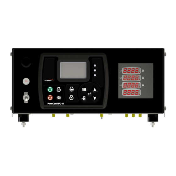
Murphy PowerCore MGC1000 Panel The Murphy PowerCore MGC1000 Panel is a dedicated Generator controller for both 120 and 480 VAC single or 3 phase. The MGC1000 is flexible in many aspects, with the ability to: •... - Page 8 Software Release: [TBD] • Prestart Delay 2 (Precrank): After a start condition has been accepted by the controller, this delay begins timing, and the prestart output turns on. When this delay expires, the output is turned off, and the start sequence continues. During this delay, the controller checks for faults, J1939 com, etc.
-
Page 9: User Interface
Software Release: [TBD] User Interface The keypads on the MPC-10 portion of the MGC1000 are comprised of 11 tactile buttons. This section describes the functions of each button. Figure 1: User Interface The buttons have the following functions: • Start Key – Allows the operator to start sequence in Manual Mode or initiate an auto start sequence when in Auto Mode (do not use in Auto Mode when set to single contact auto start method). -
Page 10: Accessing The Menu
Software Release: [TBD] Accessing the Menu The MGC1000 has 3 menu security levels to restrict users from making changes after installation. The security levels are Low, Medium and High. One may consider these security levels as user, technician and OEM. By default the low level security has a small number of menu items a user can access. - Page 11 Software Release: [TBD] System The controller System menu provides the operator with the ability to set the Date/Time, Units, Language, Brightness, Service Reminders and several other system settings. Review System under the Menu Glossary section of this manual for a full list and definition of each setting. Frequency The Frequency menu allows the operator to change and select AC Frequency setpoints such as: 50Hz or 60 Hz, alarm settings and associated time delays.
- Page 12 Software Release: [TBD] The Digital Inputs of this menu can be configured from the face of the controller to accept three types of inputs as the Active state of the input. • High, B(+) • Low, B(-) • Open The Analog Inputs of this menu can be configured from the face of the controller to accept one of four types of senders: •...
-
Page 13: Auto Start/Stop Functions Defined
Software Release: [TBD] Communication The Communications menu allows the operator to choose the type of RS485 communications such as PVA Gauge, Modbus or Local Display. The menu also allows for the operator to choose CAN termination and enabling of the CAN Parameter Map. Review Communication under the Menu Glossary section of this manual for a full list and definition of each setting. -
Page 14: J1939 Electronic Engine Setup (Factory Default)
Software Release: [TBD] 3. Access Analog Inputs and assign one Analog input for Oil Pressure and one for Engine Temperature. Press [Enter] to save the settings. 4. Press [Back] and access Relay and Digital Outputs. 5. Press down arrow to Relay1-3 or DO1-4, and assign desired outputs for Crank, Fuel, Prestart, etc. 6. -
Page 15: Setting To Auto Start On Clock
Software Release: [TBD] Setting to Auto Start on Clock NOTES: 1) Ensure the correct date and time are established in the System menu prior to establishing the Auto Start on Clock settings. 2) The Clock start timer is independent of other auto start start/stop functions. When started from the clock the controller will shut down the engine from the clock. -
Page 16: Additional Screens
Software Release: [TBD] Additional Screens Figure 9: Main Screen This is the main screen, and it displays actual and target RPM, Mode of Operation, Timer progress, % Soot Level, % DEF Level and current State, along with icons and warnings. Figure 10: First 4-Up Screen This is the first 4 up screen, displaying engine RPM, oil pressure, engine temperature and battery voltage. - Page 17 Software Release: [TBD] This screen displays the auto start/stop type and will also illustrate the throttling method for the auto start/stop. Figures 12 and 13: Regeneration Mode Screen & CAT/Perkins Regeneration Screen This is the Tier 4 Regeneration screen that is selected to be shown in the Tier 4 menu. This screen shows and allows the user to select the regeneration mode without accessing the menu, if desired.
- Page 18 Software Release: [TBD] Figure 16: Relay Status This screen will allow the operator to see what the relay status functions are set to without accessing the menu and the active setting which informs the user of the relay status. Figure 17: Digital Input Status These two screens will allow the operator to see what the digital input functions are set to without accessing the menu and the active setting which informs the user of the input status.
-
Page 19: Iso Icons
Software Release: [TBD] Figure 19: Service Life Remaining Screens These two screens provide a list of service reminders and the hours left until the internal alarm will display the services needed. All the reminders are set to 0.0 Hrs to disable by default and the screens are hidden by default. - Page 20 Software Release: [TBD] CAT/ PERKINS DPF Burner Temp (HEST). Exhaust System High Temperature Lamp Command. CAT/PERKINS - Delayed Engine Shutdown. Required for C7.1 ACERT engines having DES enabled. FPT (DEF Level – Operator Warning) – Warning DEF Level below 10% FPT (DEF Level –...
- Page 21 Software Release: [TBD] Displays when an active or unacknowledged shutdown fault exists. The icon will disappear if the fault is acknowledged and no longer active. Gear Box Pressure Fuel Rate Fuel Level Pump Flow Rate Engine Oil Level Discharge Pressure Current Oil Pressure Current RPM Ambient Temperature...
-
Page 22: Icon Troubleshooting
Software Release: [TBD] Icon Troubleshooting The warnings and shutdowns internally generated by the controller will show an Internal Fault on the top of the screen when a fault is displayed. Check all fluid levels and pressures. Ensure the cooling system and engine are functioning properly. - Page 23 Software Release: [TBD] Fuel Filter Life (Medium Security): factory set to 0 Hrs Reset Fuel Filter Life (Medium Security): resets Fuel Filter Life reminder to factory setting. Air Filter Life (Medium Security): factory set to 0 Hrs Reset Air Filter Life (Medium Security): resets Air Filter Life reminder to factory setting. Overhaul Life (Medium Security): factory set to 0 Hrs Reset Overhaul Life (Medium Security): resets Overhaul Life reminder to factory setting.
-
Page 24: Frequency
Software Release: [TBD] alternator the operator is able to set the Show Alt Excite Warning to No to allow for the pulsing without feedback. If the alternator is self-exciting or this output is not needed the control can be set to Disable to ensure no voltage is live on the output. -
Page 25: Engine Settings (Low Security)
Software Release: [TBD] Engine Settings (Low Security) Engine Type (High Security): allows the selection between J1939 and Mechanical. If Mechanical is chosen, some parameters associated with J1939 will no longer appear in the menu. Factory set to J1939. Engine Manufacturer (High Security): 1. -
Page 26: Advanced Engine Settings (Low Security)
Software Release: [TBD] Cooldown Delay (Low Security): allows the operator to set the desired cool-down time/delay for the engine. This is the length of time the engine will run at a lower speed for its cool-down cycle. Factory set to 3 minutes Advanced Engine Settings (Low Security) Address Claim (High Security): allows the operator to set the address claim of the controller when used on the CANbus. - Page 27 Software Release: [TBD] Prestart Delay (Low Security): Factory set to 00.00.00 Prestart Delay 2 (Low Security): after a start condition has been accepted by the controller, this delay begins timing, and the prestart #2 output turns on. Auto Only (Medium Security): Factory set to Disabled. Prestart Delay (Low Security): Factory set to 00.00.00 Prestart Delay 2 Mode (High Security): this setting determines if the prestart #2 output is active through the crank state or only through the prestart #2 state.
- Page 28 Software Release: [TBD] No Speed During Crank: If during the first crank, the controller does not see a speed signal from the designated speed source before this delay expires, the controller will shutdown on “No Speed Signal”. Factory set to 00:00:06. Warnings and Shutdowns (Low Security): establish alerts for the listed parameters.
-
Page 29: Input / Output Menu
Software Release: [TBD] Input / Output Menu Digital Inputs (1-5) (Medium Security): for each of the digital inputs, the ability to select the following parameters exists: Digital input 1 (Medium Security): Factory set to Function: Stop Button, Active: B-, Action: Not Used Digital Input 2 (Medium Security): Factory set to Function: Transfer Switch, Active: B-, Action: Not Used... - Page 30 Murphy Oil Temp (ES2T-250/300) Datcon Oil Temp VDO Oil Temp Murphy PMK-400 Pressure (Gear Box Pressure, Murphy PMK-400 Sensor) Analog.Digital1 Relay (1-3) and Digital (1-4) Outputs (Medium Security): these same parameters are used for both the Relay and Digital Outputs.
-
Page 31: Start / Stop Timers (Low Security)
Software Release: [TBD] Engine Running This output turns on after the engine actually starts and off when the engine stops. Digital Input (1-5) A digital input can be assigned to turn on a digital output. Analog (1-3) Digital An analog input configured to be a digital input can be assigned to turn on a digital output. -
Page 32: Communication (High Security)
Software Release: [TBD] Thursday Friday Saturday Daily Stop Time: format of HH:MM:SS (Low Security): Factory set to 12.00.00 AM. Engine Exerciser (Medium Security): This feature allows the operator to set a voltage point for when the battery voltage drops below for a given period of time the controller will provide an auto start for a defined period of time to energize the battery using the engine alternator. -
Page 33: Passcodes (High Security)
Software Release: [TBD] Parity (High Security): Factory set to None None Even PV CAN Backlight Enable (High Security): allows the MGC1000 to control the backlights of the PVCAN gauges when used with the controller. Factory set to Off CAN Termination (High Security): allows the operator to enable or disable the controller’s internal 120 ohm terminating resistor. -
Page 34: Communication Mapping
Software Release: [TBD] NOTE: If the file does not fully load due to the file being corrupt, the controller turned off during installing file, or the USB drive removed during drive the operator will be required to load a file created for the MPC-10 named configurationFull.gcibin to recover the controller from its bootloader mode. - Page 35 Software Release: [TBD] 14 = Energize to Stop Delay 15 = Engine Spindown Delay 16 = Wait to Start Delay 40008 Read Only Active Shutdown Status (Active Fault: Bit = 1, Inactive: Bit = 0) 0 = Overspeed SD (0 or 1) 1 = Underspeed SD (0 or 1) 2 = Overcrank SD...
- Page 36 Software Release: [TBD] 10 = Reserved Reserved 11 = Reserved Reserved 12 = Reserved Reserved 13 = Reserved Reserved 14 = Reserved Reserved 15 = Reserved Reserved 40011 Read Only Actual System Level Feet 40012 Read & Write Modbus Engine Start/Stop Auto Mode Only (Stop = 0, Start = 1) (0 or 1) 40013 Read &...
- Page 37 Software Release: [TBD] 40049-40050 Read & Write Pressure Maintain Value (Auto) 40051-40200 Read Only Reserved Reserved 40201 Read Only Version.App.1 Numerals 40202 Read Only Version.App.2 Numerals 40203 Read Only Version.App.3 Numerals 40204 Read Only Version.App.4 Numerals 40205 Read Only Version.Config.1 Numerals 40206 Read Only...
- Page 38 Software Release: [TBD] 40224 Read & Write Minimum Engine Speed Setpoint 40225 Read Only Service Reminder - Air Filter Life Hours 40226 Read Only Service Reminder - Air Filter Life Remaining Hours 40227 Read Only Service Reminder - Battery Life Hours 40228 Read Only...
-
Page 39: Can Parameter Map
Software Release: [TBD] 11 = Reserved (0 or 1) 12 = Run To Destruct Warn (0 or 1) 13 = Battery High Warn (0 or 1) 14 = Battery Low Warn (0 or 1) 15 = Amber Lamp Status (0 or 1) 40244 Read Only Active Warning Status (Active Fault: Bit = 1, Inactive: Bit = 0) - Page 40 Software Release: [TBD] FF91 2 Bytes Read & Write Minimum Engine Speed Setpoint FF92 2 Bytes Read & Write Maximum Engine Speed Setpoint FF93 2 Bytes Read Only System Voltage (12.5 will read 125) 2 Bytes Read Only Actual Engine Oil Pressure 2 Bytes Read Only Actual Engine Temperature...
- Page 41 Software Release: [TBD] FFA5 1 Byte Read & Write System Level Deadband (Auto) Feet FFA6 2 Bytes Reserved Reserved Reserved FFA7 2 Bytes Reserved Reserved Reserved FFA8 2 Bytes Reserved Reserved Reserved FFA9 2 Bytes Reserved Reserved Reserved FFAA 1 Byte Reserved Reserved Reserved...
- Page 42 Software Release: [TBD] Read Only High Engine Temp SD (0 or 1) Read Only Low Fuel SD (0 or 1) Read Only Low Discharge Pressure SD (0 or 1) Read Only High Discharge Pressure SD (0 or 1) Read Only Speed Signal Lost SD (0 or 1) Read Only...
-
Page 43: Supplementary Information
Software Release: [TBD] FFB7 1 Byte Read Only All Purpose Autostart Function (Current Numerals Function = Numeral Indicated) 0 = Single Contact 1 = Local Start Button 2 = Two Contact Maintained 3 = Pressure Transducer 4 = Level Transducer FFB8 1 Byte Read Only... -
Page 44: Pc Configuration Software
Software Release: [TBD] PC Configuration Software PowerVision for Controllers (PC Configuration Software) The MGC1000 controller is released utilizing Enovation Controls’ PowerVision Configuration Studio ® PowerVision allows engineering the ability to deliver quicker software updates with the flexibility of a software developer’s environment. The addition of PowerVision gives Enovation Controls the ability to provide a free-of-charge basic PC configuration program (PowerVision for Controllers) to all customers for changing default parameters within the controller. -
Page 45: Mpc-10 Specifications
Software Release: [TBD] MPC-10 Specifications Interface Display: Monochrome HR-TFT, 2.7 in. / 68mm, WQVGA (400 x 240 pixels) (3) LEDs: green (mode), yellow (warning) and red (shutdown) Operator controls: (11) Raised silicon keypads, tactile feedback Power Supply Operating Voltage: 8-32 VDC, reverse battery polarity and load-dump protected Cranking Power Holdup: 0 VDC up to 50mS (also good for brownout/blackout instances) Power Consumption: 18W max without two 1A High-side FETs active,... - Page 46 Software Release: [TBD] THIS PAGE INTENTIONALLY LEFT BLANK Section 40 00-02-1167 2018-09-18...
- Page 47 Software Release: [TBD] THIS PAGE INTENTIONALLY LEFT BLANK Section 40 00-02-1167 2018-09-18...
Need help?
Do you have a question about the PowerCore MGC1000 and is the answer not in the manual?
Questions and answers