
Subscribe to Our Youtube Channel
Related Manuals for Murphy EMS PRO


Summary of Contents for Murphy EMS PRO
- Page 1 EMS PRO Engine Monitoring System Controller Installation and Operations Manual 00-02-0716 2013-06-03 Section 40...
- Page 2 Good engineering practices, electrical codes, and insurance regulations require that you use independent external protective devices to prevent potentially dangerous or unsafe conditions. Assume that the EMS PRO can fail with outputs full ON, outputs full OFF or that other unexpected conditions can occur.
- Page 3 General Information ......................... 33 LCD CONTRAST ADJUSTMENT ON STARTUP ............33 General Wiring Precautions ..................33 Communications ......................34 ENTRY CODE SUPPLEMENT ....................38 LOADING PROGRAM ....................38 Installation ..........................39 EMS PRO Mounting and Dimensions ................ 39 Specifications ........................... 40...
- Page 4 NOTES...
-
Page 5: Introduction
Introduction This document is designed to support a user in getting familiar with the EMS PRO and how to navigate the interface, modify the settings and install and operate the controller. The Quick Set Up guide assists with establishing the different functions in the EMS PRO System Controller. Before attempting to set up the controller, be sure to read and understand this manual in its entirety. -
Page 6: User Interface And Navigation
Membrane Keypad The membrane keypad is made up of eight buttons. All of the functions for the EMS PRO can be set using these eight buttons. ICON Description “START”... - Page 7 Below are several example screens. Example Four-Up Screen Entry Code Screen Example S-Number Screen Example P-Number Screen The screens displayed by the EMS PRO are listed and described below: Screens Displayed Screen Name Description FW MURPHY or This is the last line of the text page when pressing the down arrow key from MURPHY or the default screen.
- Page 8 Screens Displayed Screen Name Description SELECTOR XXXX There are three positions displayed on this line: AUTO and MAN. When a start signal is active, the display will change to show the start option being used in place of Auto or MAN: “SINGLE CONTACT START”, “FLOAT START”, “MOMENTARY START”, “PRESSURE START”, “LEVEL START”, “TEMP START”, “CLOCK START”, “SCADA START”...
- Page 9 Screens Displayed Screen Name Description STATE: This text line displays any of the following states the controller will execute during the auto sequence: PANEL READY occurs when the key switch is in the AUTO position and • no shutdowns have occurred. The controller is waiting for an auto start condition to occur.
-
Page 10: Quick Set Up
LEVEL XX.X This displays the current system level as sensed from a transducer. (IF SELECTED) AMB TEMP XXX °F This displays the current ambient temperature as sensed from a Murphy (IF SELECTED) Model 12 transducer. LOCAL THROT This is only show if Local Throttle is selected in S36. -
Page 11: Setting The Time/Date Clock
Setting the Time/Date Clock Setting up the clock is critical to many of the other functions of the EMS PRO. Use the following steps to set the EMS PRO Clock. The clock includes the time (displayed in 24hr format), the date and the day of the week. -
Page 12: Start/Stop Settings
NOTE: (S7, 38 & 40) are the S-Numbers used to set the controller for a mechanical engine. See the S number section of this manual for details. 4. Press the [Up Arrow] and [Down Arrow] until (S38) ENGINE TYPE is displayed, press [Enter] to highlight the current setting. -
Page 13: System Throttling Types
Use the following steps to select the correct start/stop: 1. Access the S numbers menu by pressing [Menu]. 2. Use the [Up Arrow] and [Down Arrow] to scroll to the correct Entry Code (See Entry Code Supplement for Entry Codes). 3. -
Page 14: Transducer Types
NOTE: S36 is the S-Number used for the transducer type. See the S number section of this manual for details. 4. Press the [Up Arrow] and [Down Arrow] until (S36) SYSTEM THROTTLE TYPE is displayed, press [Enter] to highlight the current setting. 5. -
Page 15: Tier 4 Emissions
6. Exit the S Menu by pressing [Menu]. Tier 4 Emissions The Tier 4 Emissions set up allows users of the EMS PRO to use it on an Interim Tier 4 engine. The controller displays the SOOT level when the engine has been de-rated and/or when regeneration (regen) is required to return to normal service on the front display. -
Page 16: Unit System – Metric Or English
c. Press the [Up Arrow] and [Down Arrow] until (S84) AUTO DPF REGEN is displayed in the menu and press [Enter]. d. Press the [Up Arrow] until YES is highlighted and press [Enter]. NOTE: S84 is only available if S83”TIER 4 RATING” is set to 4, S38 “ENGINE TYPE”... -
Page 17: Start Sequence
• Transducer: Starting and stopping is controlled by S Number set points. System pressure, level, and temperature are available in the “transducer type” S Number. NOTE: SCADA START. If the engine is not already running, an auto start can be accomplished through the Modbus start/stop register. - Page 18 NOTE: WAIT FOR ECU is displayed if ECU is selected in engine type. This is a fixed 10 second delay to allow the ECU to warm up prior to cranking. • When the “WAIT FOR ECU” delay expires, the following will occur: ...
-
Page 19: Stop Sequence
NOTE: If the engine speed drops below the “crank stop” set point after the “shutdown lockout” delay expires, the engine will be shutdown on LOSS OF SPEED. NOTE: If “electronic” is selected for” engine type”, the ECU will control and arm the shutdowns. -
Page 20: Manual Start/Stop Sequence
Controller will “Go to Sleep” after 30 minutes of inactivity once engine has shutdown to conserve battery life. The controller will awake once any key is pressed or input is enabled. (This is Standby Mode) The controller is now waiting and ready for another start sequence to occur. Manual Start/Stop Sequence There is only one start option in the manual mode. - Page 21 NOTE: WAIT FOR ECU is displayed if ECU is selected in engine type. This is a fixed 10 second delay to allow the ECU to warm up prior to cranking. • When the “WAIT FOR ECU” delay expires, the following will occur: ...
-
Page 22: Special Features
NOTE: If the user does not manually throttle down the engine, it will not idle down in COOLDOWN before the engine is shut down. The clutch output is turned OFF when the engine speed drops to the “clutch disengage” RPM set point. -
Page 23: Menus
Auxiliary I/O The three auxiliary inputs control the three auxiliary outputs (1 to 1, 2 to 2, and 3 to 3). These are configurable in the S numbers. Standby Mode Standby Mode will occur when the engine is not running and the controller has not seen any activity for 30 minutes. - Page 24 S-Number Description LOP @ LOW SPD: The EMS PRO Controller gives you two oil pressure shutdown points. For engines that develop very little oil pressure at an idle, you put a lower shutdown setting in this set point. The controller automatically changes the shutdown point between the Low Speed Shutdown point and the High Speed Shutdown point.
- Page 25 S-Number Description CRANK TIME: Set this delay to the desired amount of time you want each engine cranking attempt to last. Consult your engine manual for recommended cranking and resting times (adjustable from 1 to 30 seconds). Factory set to 10. REST TIME: Set this delay to the desired amount of time you want each rest period between cranking attempts to last.
- Page 26 S-Number Description THR FDBK DLY: This set point is used to adjust the amount of time the controller waits to sample the change made by the previous throttle pulse. If the system pressure, for example, takes a long time to change based on engine speed changes, this set point should be increased.
- Page 27 RECOMMENDED TO TURN OFF ALL OTHER THROTTLING OPTIONS WHEN USING TSC1 FOR SPEED CONTROL) SENDER TYPES: This set point allows you to select between Murphy resistive sending units or VDO resistive sending units for Pressure and Temperature senders. Factory set to MURPHY SENDER.
- Page 28 S-Number Description PRESSURE MAX: Set this to the maximum value of the pressure transducer. For example, if the transducer range is 0-100 PSI, enter 100. (adjustable from -500 to 5000 PSI) Factory set to 100 PSI PRESSURE MIN: Set this to the minimum value of the pressure transducer. example, if the transducer range is 0-100 PSI, enter 0.
- Page 29 S-Number Description LVL CNT MAX: With 5 VDC or 20mA applied to the analog channel, make the top line read the same value as the bottom line. Factory set to 904. (If transducer is 0-5 VDC, enter 1023 in this set point) LVL CNT MIN: With 1 VDC or 4mA.
- Page 30 S-Number Description UNIT SYSTEM: Enter either Metric or English for displayed values. Factory set to English. TIER RATING: Enter either Tier3 or Tier4 for electronic engines. Factory set to Tier3. TIER4 STATE: Select the Regen option that best suits the application. The options to choose are AUTO DPF REGEN or INHIBIT DPF REGEN.
- Page 31 Suction”, “Fuel Leak”, “Aux. 3 Shutdown”, “Request Regen”. Factory set to Aux. 3. P-Number Description and Listing The EMS PRO Controller has P-numbers in addition to the S-numbers previously configured. These are accessed in the same manner but using a different access code. See the Secret Code Supplement for this code number.
- Page 32 P-Number Description THUR SELECT: Set this to YES if you want to start your engine on THURSDAY. Set it to NO if you want to lock out the start time on this day. Factory set to NO. FRI SELECT: Set this to YES if you want to start your engine on FRIDAY. Set it to NO if you want to lock out the start time on this day.
- Page 33 P-Number Description CLCK E MIN: This set-point lets you set the clock minute you would like to start. For example, if you want to start at 8:30 in the morning, you would adjust this until it read 30 in the minute portion Factory set to 00. CLCK F RUN TM: This set-point lets you set in the amount of time you would like your engine to run on your first start time.
- Page 34 P-Number Description CLCK K RUN TM: This set-point lets you set in the amount of time you would like your engine to run on your first start time. You have 12 available start times per day (A – L). Factory set to 0.0. CLCK K HR: This set-point lets you set the clock hour you would like to start in 24hr format.
-
Page 35: Inputs And Outputs
Inputs and Outputs When wiring to the EMS PRO Controller, please refer to the schematic illustrating connector pin outs for the following list of dedicated I/O: Digital Inputs • 1-Auto Position of Key Switch • 2-Man Position of Key Switch •... - Page 36 1-Fuel / Ignition / ECU Enable (B+) • 2-Auxiliary 1 (Tied to Aux Input #1) (B+) • 3-Alt Excite (B+) • 4-Throttle Decrease (Murphy Throttle Actuator ATO3069) (Optional Grounded Contact) • 5-Throttle Increase (AT03069) (Optional Grounded Contact) • 6-Clutch (SPDT Dry Contacts) •...
-
Page 37: General Information
This helps minimize noise generated from battery chargers and alternators, and voltage drop during cranking. Pilot excessive loads Many of the outputs on the EMS PRO Controller are rated for low current, control type loads. Do not run high current loads directly to the controller. Use stranded wire for hookup Solid wire transmits vibration and is more likely to crystallize and break when it is subjected to movement. -
Page 38: Communications
"noisy" environments. Use shielded cable on magnetic pickup Shielded cable is recommended for connecting the magnetic pickup to the EMS PRO Controller. This helps prevent signal loss and the possible coupling of electrical interference into the relatively sensitive speed sensing circuit. - Page 39 RS-232 RTS RS-232 CTS Description The EMS PRO implements a MODBUS RTU style communications protocol. The following will describe the communications and the register and coil implementation for the EMS PRO. Protocol The EMS PRO controller will reply to RTU MODBUS communications. This communications protocol uses RS232 standards set to 9600 baud rate, no parity, eight (8) bits and one (1) stop bit.
- Page 40 The maximum number of registers that can be read at one time is 125. The starting address of the registers is 40001. NOTE: If a query is made to the EMS PRO controller beyond the published amount of registers, the EMS PRO controller will ignore the message as an invalid query.
- Page 41 REGISTER TYPE DESCRIPTION Bit 6 Overspeed: (1) yes, (0) no. Bit 7 Overcrank: (1) yes, (0) no. Bit 8 High Discharge Pressure: (1) yes, (0) no. Bit 9 Low Discharge Pressure: (1) yes, (0) no. Bit 10 High System Level: (1) yes, (0) no. Bit 11 Low System Level: (1) yes, (0) no.
-
Page 42: Entry Code Supplement
The S-numbers contain critical information and control functions. Be sure that only qualified personnel have access to this entry code. The code number is 64. LOADING PROGRAM If a new program is needed, always perform a factory setup after loading into the EMS PRO. Section 40 00-02-0716... -
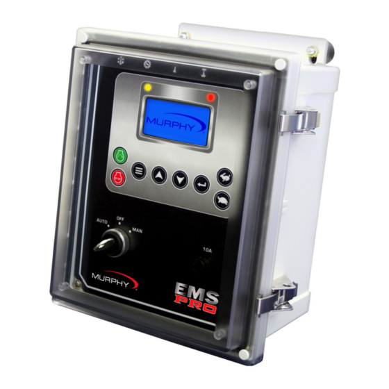
Page 43: Installation
Installation EMS PRO Mounting and Dimensions The EMSPRO should be mounted in a location that is accessible to the operator. Use connection harnesses to connect to the I/O and the engine. See the diagram below for connection instructions. Section 40... -
Page 44: Specifications
Specifications Operating Voltage: 8 VDC Minimum to 32 VDC Maximum. (Designed to work on 12 and 24 VDC systems.) Operating Temperature: -40 to 80°C (-40 to 176°F). NOTE: Care should be taken when selecting the optional clear door when used in applications involving direct sunlight exposure. - Page 45 NOTES...
Need help?
Do you have a question about the EMS PRO and is the answer not in the manual?
Questions and answers