
Related Manuals for Murphy iGUARD


Summary of Contents for Murphy iGUARD
- Page 1 Digital Generator Set Controller Installation and Operations Manual 00-02-0522 04-06-11 Section 75...
- Page 2 Disconnect all electrical power to the machine. Make sure the machine cannot operate during installation. Follow all safety warnings of the machine manufacturer. Read and follow all installation instructions. Please contact FW MURPHY immediately if you have any questions.
-
Page 3: Table Of Contents
User Interface and Navigation ..................1 iGUARD Operating Instructions .................... 3 Operating Sequence ....................3 Programming the iGUARD from the Keypad ..............5 Settings and Definitions ......................8 Operating Parameters ....................8 Communication Parameters ..................12 ... - Page 4 (THIS PAGE INTENTIONALLY LEFT BLANK)
-
Page 5: Introduction
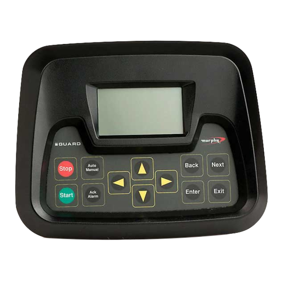
The iGUARD controller has a textured finish; UV stabilized polycarbonate injection molded housing, and is sealed with an “o” ring to help protect the iGUARD from the environment. There is a back cover protecting the Energy monitoring Board (EMB) to prevent contact with circuit board components and potentially harmful AC voltage wiring. - Page 6 Acknowledge/Alarm For warnings that do not cause a shutdown, pressing this pad will clear the alarms active at that moment. If the conditions subsequently clear and re-occur or if additional warnings occur, the common alarm output will come back on. Up / Down Arrows In program mode scrolls the menu selections and also scrolls through the choices for a given...
-
Page 7: Iguard Operating Instructions
Operating Instructions Operating Sequence The iGUARD controller, while reprogrammable, follows a standard operating sequence. This operating sequence is basically a set of machine states that happen in a pre-determined order. Machine states can be set to zero if not needed, or adjusted to fit the application. For the basic operating sequence, see the iGUARD Sequence Appendix in the Installing the Mimic/Annunciator DM/A section, this document. - Page 8 Energized to Stop The Energized to Stop timer is ON and the Energized to Stop output is active. Stopped Mode Generator has come to a complete stop. Postlube Mode In larger generators there may be a requirement for automatic lubrication after a normal start/run/stop cycle before the engine can be restarted (set to 0 to bypass).
-
Page 9: Programming The Iguard From The Keypad
Programming the iGUARD from the Keypad The iGUARD controller can be programmed in two separate ways. Most setup can be done from the front panel. There are some parameters, such as changing passwords that require the use of the iGCON software tool. The iGUARD programming menus can be accessed at any time by pressing the left and right arrows at the same time. - Page 10 What to do if you lose your Password Press NEXT until you see the screen with a graphic display of the Murphy logo. Press NEXT once to go to the system information screen. Write down the serial number, the current date, and time showing on the real time clock display, and contact us (918) 317-4100, ask for technical support).
- Page 11 ENTER and NEXT keys again to go to the next speed section. To turn off the Auto scroll function press the EXIT and NEXT keys at the same time. If the iGUARD is left on a non-scroll screen (like the Warnings/status screen) it will display only the Warning/status screen.
-
Page 12: Settings And Definitions
Settings and Definitions Operating Parameters To bring up the iGUARD Programming Screen, press the Left and Right arrow keys simultaneously. After gaining access to this screen, you can use the Left, Right, Up and Down keys to navigate from column to column and to adjust the values or change characters displayed. - Page 13 NOTE: * Newer versions of the controller/software will not have a “LOW” sensitive selection. 6. Lamp Test - Tests LCD. 7. LCD Backlight - Turns the iGUARD display backlight off, unless an error condition activates the common visual alarm. a. Disabled b.
- Page 14 a. Disabled b. Enabled - Beeps with each keypress, sounds for errors. (Default). 9. Pressure Units - User selection of display units. a. PSI (Default) b. kPa c. bar 10. Temperature Units - User selection of display units. a. Fahrenheit (Default) b.
- Page 15 17. Input - Output Test - Shows the status of the analog inputs, digital inputs, and relay outputs. a. The analog input screen shows any change in the inputs. For example if the resistance value of a resistive sender changes, the counts will change.
-
Page 16: Communication Parameters
6. Client (MASTER)” Baud Rate – communication speed on the RS-485 Client (Master) port a. 9600 b. 19200 c. 38400 (Default) NOTE: Be aware that when using the iGUARD to drive PowerView analog gages or the Remote I/O board, those devices only operate at 38400 baud. Section 75... -
Page 17: Miscellaneous Parameters
7. Modem Connection - Sets the com port for RS-232 based modem communications a. Enabled b. Disabled (Default) Miscellaneous Parameters Review the materials supplied with the engine/ECU by the manufacturer to become familiar with the specifics of your engine. 1. Engine ECU Type - Selects which ECU communications interface will be used to provide engine parameters. - Page 18 2. Crank Cut Type - Selects the primary crank and the secondary crank cuts. The options are as follows: Primary Secondary J1939 J1939 AC Freq J1939 Digit input J1939 None J1939 AC Freq Digit input None AC Freq J1939 AC Freq AC Freq Digit input AC Freq...
- Page 19 Deere Lister-Petter Detroit Mercedes Deutz Perkins Ford Volvo Other (Default) Hatz : Caterpillar, Cummins, Deere, Detroit, Deutz, Ford, GM, Hatz, Isuzu, NOTE Kubota, Lister-Petter, Mercedes, Perkins, Volvo are registered trademarks of their respective corporations 5. J1939 Crankcut Count - Is the number of consecutive measurements of the RPM above the Crankcut RPM, required to achieve crank disconnect.
-
Page 20: Engine Parameters
Engine Parameters 1. Pre-Autostart Delay - When system is in automatic mode, sets how long unit waits after a remote run signal is active before proceeding with automatic start sequence. (Default 5 seconds, set to zero to bypass.) 2. Pre-Heat Type - Determines how long the preheat output is active. a. - Page 21 10. Warm-Up Load Delay - How long the engine /generator will run before it closes the "AT LOAD" contacts. (Default ø sec.) 11. Nominal RPM - Nominal operating RPM (1800 RPM for 60 Hz, 1500 RPM for 50 Hz). (Default 1800) 12.
-
Page 22: Generator Parameters
(Default ø sec.) 4. CT Ratio - Current transformer ratio (xxx:5). (Default is 300:5) The iGUARD uses standard 5A output CT’s. - Page 23 Center Tap Delta f. Single Phase There are a number of ways to connect AC to the iGUARD. It is important to understand the options and their meaning. In the case of alternators that can be reconnected, the AC voltage and current are measured at the non-neutral junction of the coils, and if “3ph high wye”...
- Page 24 When using a Center Tapped Delta (3-phase output is 240VL-L, but L-N is 120,208,120L1, L2, and L3 respectively) this is the setup to select. Single phase (two lines and a neutral) of any configuration. 12. Generator Over Freq -Over-frequency shutdown setpoint. (Default is 65 Hz) 13.
-
Page 25: Digital Inputs And/Or Relay Outputs
NFPA-110 requires a secondary speed signal source to prevent crank re-engagement. If the iGUARD is being used in an NFPA-110 / 99 application, and there is a low speed warmup/idle required, the AC frequency cannot be used as a primary nor secondary speed signal source. - Page 26 Digital Input 8 - User Input 6. Digital Input 9 - Remote Call to Run. (Transfer switch input) Digital Input 10 - Low Lubrication Oil Level. Digital Input 11- Low Coolant Level. Digital Input 12 - Low Fuel Level Warning. ...
- Page 27 6. Low Fuel Level (warning) - When active, system indicates "low fuel level" alarm and closes the alarm contacts, but does not shutdown. 7. Fuel Leak - When active, indicates a fuel leak in the fuel containment basin, and causes an immediate shutdown.
- Page 28 (grounding) the appropriate input via an auxiliary contact on the reconnection switch. There are up to 6 selections available from the iGUARD controller. Each is fully independent (except for the CT selection) from the others. Some 480/240V reconnectable...
- Page 29 The low wye will read full output voltage (L-N) and half of the current (per phase). The high wye will read half of the output voltage (L-N) and full current (per phase). The CT’s have to be sized to read the current in the high wye configuration (The current through a conductor is identical throughout the conductor) –...
- Page 30 A more easily understood method is to connect the iGUARD to the output terminals, with the CTs sized for maximum current in the low wye configuration. This way, the controller can read what is actually coming out of the generator, without any need to interpolate and assume. This will offer increased accuracy, and is generally easier to understand.
- Page 31 7. Shutdown - Activated only by a fault shutdown. 8. Common Alarm - Any warning or shutdown condition will activate the relay. 9. Remote Alarm - Any alarm condition will actuate this output; can be de-energized by an ACK or by a reset condition. 10.
- Page 32 24. Low AC Voltage - Relay operates when AC voltage falls below the setpoint - ACK or reset to clear. 25. High AC Voltage - Relay operates when AC voltage rises above the setpoint - ACK or reset to clear. 26.
- Page 33 44. Running Cooldown 45. Air Damper N/Energized 46. Run to Destruct Enabled 47. Energized to Stop - Relay turns ON at shutdown and stays on for length of ETS timer. 48. Engine running - Engine speed is above crank disconnect speed 49.
-
Page 34: Analog Inputs
4-20mA or 0-5VDC type signals. The iGUARD uses variable precision current sources to accommodate many different brands of resistive senders as well as true detection of open/missing sender and sender shorted to ground. - Page 35 VDO Fuel output board Required) 0 - 5VDC VDO Pressure special Datcon Oil Temp (Optional output board Required) 0 - 5VDC current Murphy Oil Temp Datcon Oil Sender VDO A Oil Temp Murphy Oil Sender BMI Oil Temp Clock Start/Stop Parameters 1.
- Page 36 Most applications will require that ground be applied as the signal that an input is active. The standard iGUARD connection diagrams show this type of connection. However, some applications either require or are much easier to implement using a positive +V battery signal to indicate the input is active.
- Page 37 Relay Functions Display All relay functions that are active will be displayed on the screen. If a relay has been assigned a function that is currently active, then that relay number will appear to the left of the active relay function name. Relay designation is displayed in sequence.
- Page 38 The ECU is sending out a Wait-to-Start message. 4. If there are no "Wait to start" conditions, the iGUARD begins a normal start cycle, or if there are one or more "Wait to Start" signals, the iGUARD waits for them to clear before proceeding.
- Page 39 Plus a number of status bits - such as wait to start, and the lamp codes (Shutdown, warning, maintenance). The iGUARD displays active fault codes*. Additionally, the engine faults and severity for the most common faults and warnings are displayed not only as the Suspect Parameter Number, (SPN) and failure mode indication (FMI) but also in plain text.
-
Page 40: Manufacturers Specifics
Notes: John Deere originally implemented J1939 revision 2. When finalized, it implemented revision 4 of the standard. As long as the iGUARD is set to "DEERE" as a manufacturer, we can determine the ECU software revision and automatically accommodate for this version. - Page 41 J1939 enabled. The existing G-Drives are MODbus protocol RS-485 connection, and are not currently (May 2003) supported by the iGUARD. This support will eventually be added in the planned phase two firmware release. Contact the factory (918) 317-4100 about availability.
-
Page 42: Iguard Typical Installation And Mounting
‘doghouse’ of an AC alternator. When the iGUARD is used as a standalone device, it must be mounted within a protective housing. Refer to the cutout schematic (below) for layout of the cutout and mounting screw holes. - Page 43 Dimensions and Cutout Schematic Section 75 00-02-0522 04-06-11 - 39 -...
- Page 44 Typical Connector Layout iGUARD Typical Components The iGUARD Controller Components 1. Bezel / Faceplate 2. O-Ring 3. User Interface Board 4. I / O Board 5. Energy Monitoring Board 6. Cover 7. Standoffs Section 75 00-02-0522 04-06-11 - 40 -...
-
Page 45: Iguard Electrical Installation
Electrical Installation Electrical Hook up There are several wire harnesses or wire harness plug-in connectors that may be shipped with the controller. Two (2), 10-position connector: for J1939, RS485 / RS232 One (1), 16-position connector: for Digital Inputs ... - Page 46 J3 – Communications Connector This communications connector supports RS-232 for programming the controller with the iGCON software tool, modem connection and the Modbus client (master) connection J5 – Digital Inputs 1 - 8 Section 75 00-02-0522 04-06-11 - 42 -...
- Page 47 NOTE: Murphy recommends the use of two wire senders, with the sender return connected to the analog channel. If single ended senders are used, with ground provided at the sender itself, there can be a number of problems that may or may not affect any given installation.
- Page 48 J8 – Positive Emergency Stop J8 - is the positive emergency stop. From the factory there is a loop from terminal 1 to terminal 2. The controller will power up, but will not operate the relays without this connection. If your application requires a true positive emergency stop, we recommend that you install a normally closed type switch between terminals 1 &...
-
Page 49: Energy Monitoring Board (Emb)
I/O Board Relays The 8 relays mounted on the I/O board are pre-programmed at the factory to: Relays may be re-assigned to any of the other desired functions at will from the front panel. Energy Monitoring Board (EMB) From the rear of the unit, there is a smaller board on the left side. This is the energy monitoring board. - Page 50 In 3-phase applications apply: phase A to terminal 1 phase B to terminal 2 phase C to terminal 3 neutral to terminal 1 In single phase applications apply: phase A to terminal 1 phase B to terminal 2 neutral to terminal 4 In Center Tapped Delta applications, apply: phase A to terminal 1 phase B to terminal 2...
- Page 51 (~.25 Ohms) so the common mode voltage will be well within a safe range. In applications where the CT’s are commoned together (4 wires - CT1+, CT2 +, CT3+ and CT common) the system will only read 1/2 of the current signal, unless the iGUARD is programmed to reflect commoned CT’s.
- Page 52 AC neutral if you wish. There is a software selection in the iGUARD that must be set appropriate to the connection method you are using. See Operating Sequence in the iGUARD Operating Instructions section in this document.
- Page 53 An extractor tool might also be necessary in case of a broken wire, misinserted terminal, or when a wire needs to be removed. Section 75 00-02-0522 04-06-11 - 49 -...
-
Page 54: Installing The Mimic/Annunciator Dm/A
(Master) controller. The Mimic/Annunciator features the front bezel display which includes the user interface board and Modbus device that communications with the iGUARD (Master) controller and a wire cover. To operate the DM/A, power must be supplied to the J1 connector on the rear of the unit. - Page 55 3. LCD backlight - This selects whether the LCD backlight is enabled or not. If disabled, the backlight will not come on. Default is enabled 4. iGUARD beeper - This selects whether or not the station beeper is enabled. If disabled, the station will not sound any audible alarm for faults or warnings. Default is enabled.
- Page 56 The selections are "Mimic" and "Annunciator" In Mimic mode, the remote station is allowed to behave exactly as if it were the front panel of the actual iGUARD - the user may start and stop manually, change between automatic and manual modes, acknowledge alarms, and reset the system.
- Page 57 Non-ECU Wiring Section 75 00-02-0522 04-06-11 - 53 -...
- Page 58 Section 75 00-02-0522 04-06-11 - 54 -...
- Page 59 Three Phase Wiring iGUARD Single Phase Wiring Section 75 00-02-0522 04-06-11 - 55 -...
- Page 60 In Center Tapped Delta Wiring Section 75 00-02-0522 04-06-11 - 56 -...
- Page 61 Sequence Appendix Section 75 00-02-0522 04-06-11 - 57 -...
-
Page 62: Specifications
Specifications Mounting (Cutout) Dimensions: 7.05 x 5.25 x 2.76 in. (179 x 133 x 70 mm). Mounting Screws: 4, #6-32 screws and nitrile rubber o-ring are supplied to meet NEMA4 specs. Case Material: Black Polycarbonate, textured finish, UV stabilized. Connection: 600V rated multi-wire quick connect for DC and AC connections, suitable for wire harnessing. -
Page 63: Iguard Options And Accessories
Options and Accessories Section 75 00-02-0522 04-06-11 - 59 -... - Page 64 Murphy Industries, Inc., with all rights reserved. (c) 2011 Murphy Industries, Inc. Other third party product or trade names referenced herein are the property of their respective owners and are used for identification purposes only.
Need help?
Do you have a question about the iGUARD and is the answer not in the manual?
Questions and answers