
Related Manuals for Murphy PowerCore TEC-10


Summary of Contents for Murphy PowerCore TEC-10
- Page 1 ® PowerCore Model TEC-10 Installation Manual Products covered in this document comply with European Council electromagnetic compatibility directive 2014/30/EU and electrical safety directive 2014/35/EU. 00-02-0977 2018-02-23 Section 30...
- Page 2 In order to consistently bring you the highest quality, full-featured products, we reserve the right to change our specifications and designs at any time. The latest version of this manual can be found at enovationcontrols.com. BEFORE BEGINNING INSTALLATION OF THIS MURPHY PRODUCT: • Read and follow all installation instructions.
-
Page 3: Table Of Contents
Table of Contents Operations Manual Location ..........2 Hardware Installation ............. 2 Inspecting Package Contents ........2 Tools Needed ............... 2 Installation ..............3 Dimensions for Installation ........... 4 PIN Specifications ..............6 Accessories ................7 Specifications ................8 Interface ............... 8 Power Supply ............... - Page 4 The TEC-10 can be set as an AutoStart Controller. Please be cognizant at all times of hands and other objects that are in close proximity to the machine(s) being controlled as they may commence operation suddenly and without warning. LENS CLEANING PROCEDURES The lens on the TEC-10 is composed of Polycarbonate materials.
-
Page 5: Operations Manual Location
Operations Manual Location After installation, please review the TEC-10 Operations Manual prior to placing the controller into service. In order to access the TEC-10 Operation Manual, please visit: support.enovationcontrols.com Then search for TEC-10. Download the latest manual by clicking the link under the Manuals section of the page. Hardware Installation Inspecting Package Contents Before attempting to install the product, it is recommended that... -
Page 6: Installation
Installation Preparing the Enclosed Panel Determine the location of the TEC-10 Panel on the customer- supplied mounting bracket or plate. The suitability of the location is subject to investigation by the local authority having jurisdiction at the time of the installation. Recommended torque for tightening both the shockmounts into the panel and the nuts on the shockmounts is 78 inch-pounds or 8.8 Nm (Newton Meters). -
Page 7: Dimensions For Installation
Dimensions for Installation Front Inches [mm] Side View Section 30 00-02-0977 2018-02-23 - 4 -... - Page 8 Back View Section 30 00-02-0977 2018-02-23 - 5 -...
-
Page 9: Pin Specifications
PIN Specifications 21 Pin Connector (A) 31 Pin Connector (B) Unavailable Unavailable Battery (positive) Unavailable Unavailable Unavailable Relay 1, +DC (10A), Default Setting: Crank Unavailable Battery (negative) Unavailable J1939 CAN Shield Unavailable Relay 2, +DC (10A), Default Setting: ECU Unavailable Enable Unavailable Unavailable... -
Page 10: Accessories
Accessories Part Description Number 40000602 Engine Harness, 21 Position Connector 10’ Whip Harness (3m approx.) 40000603 I/O Harness, 31 Position Connector 10’ Whip Harness (3m approx.) 40000479 Deutsch Connector Kit, 21-pin and 31-pin, Panel Connector Kit 40000531 Deutsch Connector Kit, 21-pin, Panel Connector Kit, Engine Only 78700046 Deutsch Connector Kit, 31-pin, Panel Connector... -
Page 11: Specifications
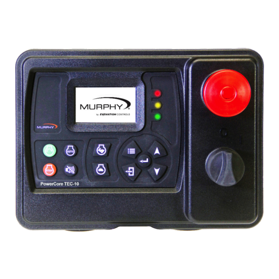
Specifications Interface Display: Monochrome HR-TFT with backlight 2.7” / 68 mm, WQVGA (400 x 240 pixels) Languages: English, Spanish, German, French, Italian (3) LEDs: Green (mode), Yellow (warning) and Red (shutdown) Operator Controls: (11) Raised silicone keypads, tactile feedback (1) Rotary key switch, power on/off (1) Push switch (red), engine stop Power Supply Operating Voltage: 8-32 VDC, reverse battery polarity and load-dump protected...
Need help?
Do you have a question about the PowerCore TEC-10 and is the answer not in the manual?
Questions and answers
I have a compressor with two extra emergency stop buttons they do not work.Could the Powercore unit be programed to ignore them?
No, the Murphy PowerCore TEC-10 unit cannot be programmed to ignore extra emergency stop buttons on a compressor. Emergency stop inputs are critical safety features and are typically hardwired for safety compliance. The manual does not indicate an option to disable or ignore emergency stop inputs.
This answer is automatically generated