
Related Manuals for Murphy MX4 Series


Summary of Contents for Murphy MX4 Series
- Page 1 Interchange™ Comm Control Module, MX4 Series Installation and Operations Manual 00-02-0695 12-06-11 Section 50...
- Page 2 EXPLOSION HAZARD: WHEN IN HAZARDOUS LOCATIONS, TURN OFF POWER BEFORE REPLACING OR WIRING MODULES. EXPLOSION HAZARD: DO NOT DISCONNECT EQUIPMENT UNLESS POWER HAS BEEN SWITCHED OFF OR THE AREA IS KNOWN TO BE NON-HAZARDOUS. Please contact FW MURPHY immediately if you have any questions.
-
Page 3: Table Of Contents
Table of Contents Murphy Interchange Comm Control Module Series ............1 MX4 Thermocouple / MPU ................... 1 Product Dimensions and Mounting ................1 Accessories ........................1 Specifications ....................... 1 MX4 Installation Instructions ..................1 ... - Page 4 (THIS PAGE INTENTIONALLY LEFT BLANK)
-
Page 5: Murphy Interchange Comm Control Module Series
Murphy Interchange Comm Control Module Series The MX4 expansion module provides temperature and frequency input capability to existing and future Murphy Controllers using CANBUS proprietary communications. Modbus® RTU RS485/RS232 is also provided for other communication requirements. Any mix of MX-Series modules can be added to enable Digital and Analog I/O, and Thermocouple functionality for communication and monitoring by the master controller. -
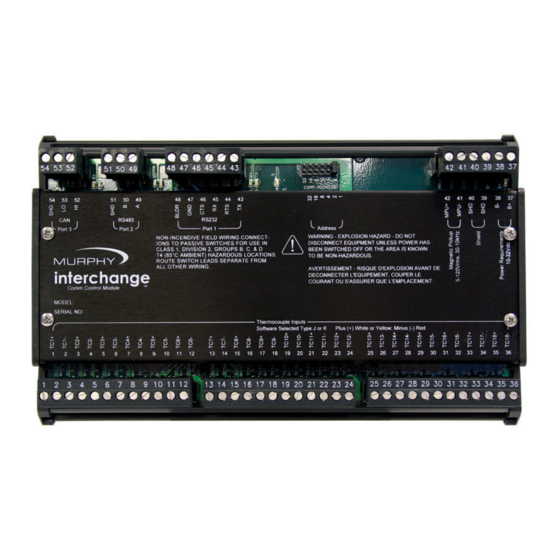
Page 6: Installation Diagram
Installation Diagram Section 50 00-02-0695 12-06-11 - 2 -... - Page 7 Section 50 00-02-0695 12-06-11 - 3 -...
-
Page 8: Mx4 Jumper Configuration
MX4 Jumper Configuration CANBUS: Communication Link to Main I/O Module LK1: This jumper provides a termination resistor for the CAN communication chain. This jumper must be in place only when the I/O module is the last in the communication chain. See control panel drawings for designation. The cover of the MX4 must be removed to access this jumper link (LK1). - Page 9 RS485 Communication Port: Slave Comm. Port. (See Pictorial Above) LK2: These jumpers provide a termination, pick-up, and pull-down resistors for RS485 communication chain. The PU/PD jumpers should only be in one place on the communication chain. The TR jumper must be in place only when the I/O module is the last in the communication chain.
-
Page 10: Communications
Communications Physical Layer: The MX4 module features one asynchronous RS232 serial communication port, one asynchronous RS485 serial communication port, and one CANBUS 2.0B proprietary communication port. RS232 Interconnect: The module is equipped with screw terminals called Port 1. This connection is typically used to poll the information for a specific module using twisted shielded pair cable suitable for RS232 networks. -
Page 11: Mx4 Expansion Module - Modbus Rtu Description
Communication Address Select Shunts: A jumper shunt header is provided to assign a unique Modbus RTU and/or CANBUS address to each expansion module that may be in the network. This allows the master controller to differentiate between the modules. Addressing is done in binary format, and each incrementing jumper increases the weight by a factor of 2. - Page 12 Modbus Read/ Description Definitions Range Data Units Register Write 40033 Raw count Thermocouple input 11 R 0 ‐ 4095 A/D count 0 = 0.0 VDC, 4095 = 4.096 VDC 40034 Raw count Thermocouple input 12 R 0 ‐ 4095 A/D count 0 = 0.0 VDC, 4095 = 4.096 VDC 40035 Raw count Thermocouple input 13 R 0 ‐ 4095 A/D count 0 = 0.0 VDC, 4095 = 4.096 VDC 40036 Raw count Thermocouple input 14 R 0 ‐ 4095 A/D count 0 = 0.0 VDC, 4095 = 4.096 VDC 40037 Raw count Thermocouple input 15 R 0 ‐ 4095 A/D count 0 = 0.0 VDC, 4095 = 4.096 VDC 40038 Raw count Thermocouple input 16 ...
- Page 13 Modbus Read/ Description Definitions Range Data Units Register Write 40064 Cold junction 2 temperature R ‐400 to +1850 F deg F X10 40065 Factory Use R 40066 Factory Use R 40067 Temperature thermocouple 1 R ‐2000 to +25000 deg F X10 40068 Temperature thermocouple 2 R ‐2000 to +25000 deg F X10 40069 Temperature thermocouple 3 R ‐2000 to +25000 deg F X10 40070 Temperature thermocouple 4 R ‐2000 to +25000 deg F X10 40071 ...
- Page 14 Modbus Read/ Description Definitions Range Data Units Register Write 40103 Temperature input 16 type R/W 0 ‐ 1 0 = J, 1 = K 40104 Temperature input 17 type R/W 0 ‐ 1 0 = J, 1 = K 40105 Temperature input 18 type R/W 0 ‐ 1 0 = J, 1 = K 40106 Cold junction 1 temperature offset R/W ‐32768 to +32767 deg F 40107 Cold junction 2 temperature offset R/W ‐32768 to +32767 deg F 40108 Factory Use R 40109 Communication timeout R/W 0 – 65535 ...
- Page 15 Register 40001 Value Description Register 40,001 is a read-only register. This register holds the model number of the hardware. If you are using multiple Comm modules, it is sometimes helpful to confirm that you are communicating with the expected module type. In this case, it will return 279. Register 40042 Value Description Register 40,042 is a read-only register.
Need help?
Do you have a question about the MX4 Series and is the answer not in the manual?
Questions and answers