Table of Contents
Advertisement
Quick Links
Advertisement
Table of Contents

Related Manuals for Petsafe PIG00-17440


Summary of Contents for Petsafe PIG00-17440
- Page 1 Get Started!
-
Page 2: Before We Begin
Follow the instructions in this guide to design and test your fence layout before burying the boundary wire. If you need additional setup help, please visit support.petsafe.net or call our friendly Customer Care team. Fit the receiver Proper fit is essential to the effectiveness of the receiver collar and the safety of your pet. -
Page 3: What You Have
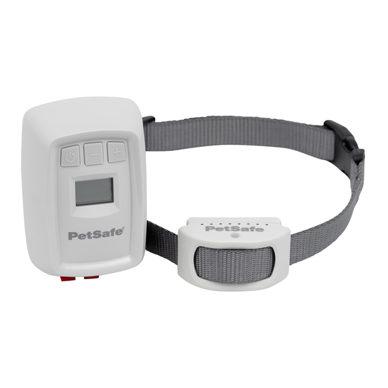
What you have Decrease boundary distance Increase boundary distance Short contact points Power button Correction level lights LCD screen Status light Mounting hardware Receiver collar Power connector Transmitter Long contact points Boundary wire terminals Gel-filled capsules Boundary wire Receiver collar Transmitter power Wire connectors (500 feet) -
Page 4: What You Need
This is especially important if you live in an area where • Staple gun — if attaching boundary wire to an existing lightning storms are common. You can purchase the PetSafe ® wooden fence Surge Protector at petsafe.com or by contacting our Customer Care team. - Page 5 Warning zone Pet area Static correction zone Place transmitter inside Boundary Boundary distance width The following safety features are active whenever the receiver collar is set to static correction: Anti-linger To discourage your pet from lingering in the warning zone and draining the receiver collar’s rechargeable battery, the system will deliver a static correction to your dog any time he fails to return to the pet area within prevention 2 seconds of receiving a tone and vibration warning from the receiver collar.
-
Page 6: Have Your Utilities Marked
Set up your fence Have your utilities marked Charge the receiver collar Buried cable 90° Boundary wire 1. Call your utility company to have your utility lines marked. In most 1. Locate the charging jack on the bottom of the receiver collar, areas, this is a free service. -
Page 7: Install The Transmitter
• Near a window or on a wall you can drill through, since the boundary wire will run from the transmitter and exit the 3. If you purchased a PetSafe ® Surge Protector (LP-4100-1), building. - Page 8 Plan your fence layout Use our fence planner at Acres fenceplanner.petsafe.net/inground to try out different fence Feet of wire layouts and estimate how much boundary wire you will need. The 1 180 1870 required table at the right indicates the approximate length of boundary wire needed for a square, single loop layout.
- Page 9 • The fence signal may activate the receiver collar inside your house if the boundary wire runs along the outside wall. If this occurs, remove your pet’s receiver collar before bringing him inside, decrease the boundary distance, or consider an alternate layout. •...
- Page 10 Single loop layout examples Place transmitter inside Pets can safely cross twisted wires Pets can 10 twists/ft safely cross twisted wires Perimeter loop Full perimeter loop using existing fence The perimeter loop is the most common layout. This will allow This layout allows you to include your existing fence as part of your your pet to roam your entire property freely and safely.
- Page 11 Double loop layout examples Place transmitter inside Front or back property only Front boundary only From the fence transmitter, run the wire to point A, then to point B From the fence transmitter, run the wire to point A, then to point B. and so on (B to C to D to E to F).
- Page 12 Waterfront property Wire loop attached to existing fence From the fence transmitter, run the wire to point A, then to point This layout allows you to include your existing fence as part of B. Make a U-turn and follow your path to C, then to D, then to E. your layout and keep your pet from jumping out or digging under Next, make another U-turn and follow the same path all the way your existing fence.
-
Page 13: Position, Twist And Splice The Boundary Wire
Position, twist and splice the boundary wire 1. Starting at the transmitter, run the wire all the way around your boundary), twist the outgoing and incoming wires together 10- planned perimeter and back to the transmitter. To avoid twists 12 times per foot. This cancels the fence signal and allows your in the wire, insert an object such as a pencil or screwdriver pet to cross without receiving a correction. - Page 14 Your system comes with two gel-filled splice capsules to ensure that your splices are waterproof. We recommend using these capsules for all splices in your boundary to ensure reliable fence operation over time. Additional splice capsules are available for purchase at www.petsafe.com or by contacting our Customer Care team.
-
Page 15: Connect The Wires
Connect the wires Important: If you are using a PetSafe Surge Protector (LP-4100-1), skip the steps in this section and instead follow the instructions ® provided with the surge protector to connect the boundary wire to the transmitter and surge protector. - Page 16 4. Press the power button on the transmitter to turn it on. 5. Set the boundary distance to 10: The LCD screen on the transmitter will turn on and display the • To decrease the boundary distance, press the - button. boundary distance.
-
Page 17: Prepare The Receiver Collar
Prepare the receiver collar White lights = static correction level 1–7 Yellow light = tone and vibration only Mode button 1. Turn the receiver collar on by pressing and holding the mode 2. To determine the current correction level, press the mode button button for 1 second. - Page 18 Set the boundary distance and test the receiver collar With the boundary wire in place and properly connected, it’s time to set the boundary distance and test the system. 1. First, make sure the: • Transmitter is on and the boundary distance is set to 10. •...
- Page 19 Warning zone Static correction zone Pet area 4. Adjust the boundary distance setting to establish the warning zone. We recommend setting it so that the warning zone begins at least 10 feet before the boundary wire. When adjusting the boundary distance, consider the size of your yard and the height and temperament of your pet. A wide boundary distance may work well for a tall, high-energy dog in a spacious yard, but may be unnecessarily restrictive for a short, timid pet or a limited yard.
-
Page 20: Bury The Boundary Wire
Bury the boundary wire Important: Always test your fence system to make sure it is operating properly before burying the boundary wire. 1. Unplug the fence transmitter. 2. Cut a trench 1 to 3 inches deep along your planned boundary. The trench only needs to be as wide as the wire. Avoid all underground cables as you dig. - Page 21 Use an existing fence You can attach the boundary wire to a chain link fence, split rail fence or a wooden privacy fence. The boundary wire can be attached as high as needed; however, make sure to set the boundary distance at a high enough range for your pet to receive the signal. Weave wire into fence Single loop Staple wire into fence...
-
Page 22: Place The Boundary Flags
Place the boundary flags The boundary flags are a visual reminder to help you and your pet learn where the warning zone is located. To place the boundary flags: Boundary wire Warning zone Warning zone Pet area Pet area 10-foot flag spacing 1. -
Page 23: Fit The Receiver Collar
2. With your pet standing comfortably, place the receiver collar around your dog’s neck. The PetSafe logo should be right side 5. Once you are satisfied with the fit of the receiver collar, remove ®... -
Page 24: System Test
Surge Protector (LP-4100-1) the system test procedure will vary. Instead of following the steps in ® this section, please visit our support site at support.petsafe.net and search for “test your wired fence system.” 1. Make note of your boundary distance setting and receiver 7. -
Page 25: Wire Break Location Test
Wire break location test There are two types of wire breaks: full and partial. In a full break, 4. Connect one end of the test wire to the other terminal on the the boundary wire is completely broken or cut. In a partial break, transmitter. -
Page 26: Troubleshooting
Troubleshooting The receiver collar is not • Charge the receiver collar. beeping or correcting. • Make sure the transmitter LCD screen is on and that the wire break warning alarm is not sounding. If the wire break warning alarm is sounding, perform the System test. The receiver collar is •... - Page 27 The transmitter will not • Make sure the transmitter is connected to the power adaptor. turn on. • Check that the power adaptor is plugged in properly. • If the system is plugged into an RCD or GFCI outlet, check to see if the circuit has been tripped. Reset the RCD or GFCI circuit if required.
- Page 28 For questions or additional tips: +1 (800) 732-2677 petsafe.com 1-Year Warranty | ©2021 Radio Systems Corporation | Models: PIG00-17440, ZIG00-17510 | YU400-2533/1 For important safety instructions, please see the customer care guide. For a list of patents protecting this product, please visit radiosystemscorporation.com/patents...
Need help?
Do you have a question about the PIG00-17440 and is the answer not in the manual?
Questions and answers