Table of Contents
Advertisement
OPERATING MANUAL
This manual MUST be kept and stored with the aerial platform at all times.
800 275-9522
For Service please call .....................................................................
Skyjack Inc. Service Center, 3451 Swenson Ave., St. Charles, IL. 60174 ... FAX 630 262-0006
800 965-4626
For Parts in North America and Asia please call ....................................
Skyjack Inc. Parts Center, 3451 Swenson Ave., St. Charles, IL. 60174 ............. FAX 888 782-4825
31 297 255 526
For Parts & Service in Europe please call ....................................................
Skyjack Europe Communicatieweg 29, 3641 SG Mijdrecht Netherlands ............. FAX 31 297 256 948
122883AH
Printed in Canada
June 2002
Advertisement
Table of Contents

Subscribe to Our Youtube Channel
Related Manuals for Skyjack SJ-600 Series


Summary of Contents for Skyjack SJ-600 Series
- Page 1 This manual MUST be kept and stored with the aerial platform at all times. 800 275-9522 For Service please call ..............Skyjack Inc. Service Center, 3451 Swenson Ave., St. Charles, IL. 60174 ... FAX 630 262-0006 800 965-4626 For Parts in North America and Asia please call ........
- Page 2 WARNING This Operating Manual and the “ANSI/SIA Manual Of Responsibilities” are considered fundamental parts of the elevating work platform. They are a very important way to communicate necessary safety information to users and operators. A complete and legible copy of these manuals MUST BE KEPT ON THE WORK PLATFORM in the provided weather resistant storage compartment at all times.
-
Page 3: Table Of Contents
Table Of Contents Section - Paragraph Page No. Section 1 - Introduction Purpose Of Equipment ......................7 Use Of Equipment ........................7 Warnings ............................ 7 Description ..........................7 Operator Warnings ........................8 Specifications And Features ..................... 9 Standard Features And Optional Equipment ................ 10 Work Platform Major Component Identification .............. - Page 4 You, as a careful operator, are the best insurance against an accident. Therefore, proper usage of this work platform is mandatory. The following pages of this manual should be read and understood completely before operating the work platform. Any modifications from the original design are strictly forbidden without written permission from SKYJACK, Inc. DANGER ELECTROCUTION HAZARD MAINTAIN SAFE CLEARANCES FROM ELECTRICAL THIS MACHINE IS NOT INSULATED.
- Page 5 INJURY COULD RESULT FROM IMPROPER USE OF THIS EQUIPMENT! SERVICE POLICY AND WARRANTY SKYJACK, Inc. warrants each new work platform to be free of defective parts and workmanship during the first 12 months. Refer to Warranty Statement on Page 6 for details.
- Page 6 Skyjack within 15 days from the time of billing. within the dealers specified territory, limited to a When work platforms are put into stock, the warranty maximum of four (4) hours.
-
Page 7: Section 1 - Introduction
Purpose Of Equipment Base - (600 & 800 Series) The base is a rigid The SKYJACK SJ-600, 800 & 1000 Series Work one piece weldment which supports two component Platform is designed to transport and raise personnel, side cabinets. One cabinet contains the hydraulic tools and materials to overhead work areas. -
Page 8: Operator Warnings
BE AWARE maintenance and when ordering service parts. areas in case of overhead obstacles. Optional Accessories - The SKYJACK Work that there is no person(s) in the path of ENSURE Platform is designed to accept a variety of optional travel. -
Page 9: Specifications And Features
Table 1-1 Specifications And Features Family 600 Series 800 Series 1000 Series Model 7027 7127 7135 8831 8841 9250/9250A † 8,600 lbs. 7,920 lbs. 9,550 lbs. 9,757 lbs. 11,410 lbs. 14,200 lbs. Weight* (3450kg) (3593kg) (4332kg) (4426kg) (6441kg) (5176kg) 70” 71.5”... -
Page 10: Standard Features And Optional Equipment
Table 1-2. Standard Features and Optional Equipment Standard Features (ANSI & CE) • Operator Horn • Joystick Control • Dual Range (torque/speed) Selector • Movement Alarm (ANSI) • Diamond Pattern, All Steel Platform Deck Construction • Hinged Railing System With 6” (15.24cm) Toe Boards •... -
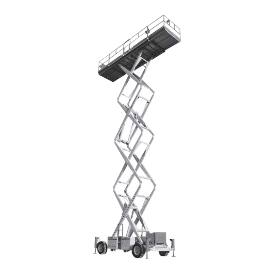
Page 11: Work Platform Major Component Identification
CONTROL BOX ENTRY MAIN GATE PLATFORM LIFTING MECHANISM HYDRAULIC TANK AND FUEL TANK SIDE CABINET HYDRAULIC/ ELECTRIC ENGINE SIDE TRAY CABINET Figure 1-1. SKYJACK SJ-800 Series Work Platform SJ 600, 800 & 1000 Series SECTION 1, Page 11 May 2002 122883AH... -
Page 12: Section 2 - Operation
SECTION 2 OPERATION Operating Controls Identification Emergency Battery Disconnect Switch The following descriptions are for identification, explanation and locating purposes only. A qualified operator MUST read and completely understand these descriptions before operating this work platform. Procedures for operating this work platform are detailed in the “OPERATING PROCEDURES”... -
Page 13: Engine Control Panel
Engine Control Panel (Dual Fuel) Engine Control Panel (Diesel) Figure 2-3A. Engine Control Panel - Ford Gasoline Engine (Shown with Dual Fuel) Figure 2-3B. Engine Control Panel - Kubota Diesel Engine Engine Control Panel - This control station is Engine Control Panel - This control station is attached to the Engine Roll-out at the front of the base. -
Page 14: Base Control Box/Station
Base Control Box/Station (CE) Emergency Powered Extension Platform Retraction System (CE) 1000 Series only) Figure 2-4A. Base Control Box and Labels (Located at rear of hydraulic/electric side cabinet) Figure 2-5. Powered Platform Emergency Retraction Push-Button 1. Powered Platform Emergency Retraction Push-button - This switch, when depressed, activates the platform retraction system on the platform in the Figure 2-4B. -
Page 15: Platform Controls Operator's Control Box
Platform Controls 5. Enable Push-Button - When depressed and Operator’s Control Box held, this push-button switch brings power to the lift or outrigger circuits. 6. Emergency Stop Button - When struck, this red push-button switch disconnects power to the control circuit. -
Page 16: Outrigger Controls
Outrigger Controls (Option) Hydraulic Generator Control (Option) (Model 9250A, 7135 & 800 Series ) Figure 2-9A. Hydraulic Generator Control On The Main Control Box Figure 2-8A. Outrigger Controls On Operator’s Control Box Figure 2-9B. Hydraulic Generator Control On The Auxiliary Control Box Hydraulic Generator Control - Located on the side of the Operator’s Control Box or on the Auxiliary Control Box console. -
Page 17: Identification And Operation Of Safety Devices
Identification And Operation of Base Controls - Manual Safety Bar Safety Devices Fold-Down Guardrail System Figure 2-13. Safety Bar Safety Bar - Designed to support the scissors assembly (when properly positioned), the safety bar MUST be used for inspection and performing maintenance or repairs within the scissors assembly. -
Page 18: Operating Procedures
Operating Procedures Warning Explosion Hazard following descriptions Operating Procedures. A qualified operator MUST read and completely understand these descriptions before Keep flames and sparks away. DO NOT smoke near operating this work platform. batteries. First Aid Set-Up Procedure Immediately flush eyes with cold water if electrolytic acid is splattered into them. -
Page 19: Prestart Checks
OF THIS EQUIPMENT! Use the Down Switch to lower the platform to it’s fully lowered position. Your SKYJACK Model is now ready for use by an authorized, qualified operator who has read and completely understands ALL of Section 2, OPERATION in this manual. -
Page 20: Operator Qualifications
Operator Qualifications Insert key into the Off/Lift/Drive Select Key Switch, then select “LIFT” or “DRIVE”. Select “LOW” position with HI/LOW Throttle Select Switch. Only trained and authorized persons should use this work platform. Safe use of this work platform requires If the engine is cold, depress and hold the Engine the operator to understand the limitations and Choke Push-button (Gasoline engines) or... -
Page 21: Shutdown Procedure
To Steer: Select “DRIVE” position with Off/Lift/ Shutdown Procedure Drive Select Key Switch. Activate and hold the Drive Enable trigger switch (by squeezing it Completely lower the platform. towards the joystick), then press the rocker switch on top of the Drive/Steer Controller handle Turn key to “OFF”... -
Page 22: Emergency Lowering System
Emergency Lowering System Emergency Lowering System (600 & 800 Series) (1000 Series only) Figure 2-14. Emergency Lowering System Emergency Lowering System - This system allows platform lowering in the event of an emergency or an electrical system failure. 1. Holding Valve Manual Override Knob - Located on the holding valve at the bottom of each lift cylinder, Figure 2-15. -
Page 23: Outrigger Operating Procedures
Outrigger Operating Procedures D. During Operation If alarm sounds during operation, the platform A. Before Operation is not level. LOWER PLATFORM Check overhead clearances and ground Make necessary IMMEDIATELY! obstructions. This will require the operator to adjustments to level the machine! move around the platform. - Page 24 Start the machine and turn the throttle switch to Warning the high idle setting. manually disengage the parking brakes if DO NOT the work platform is on a slope. Inverter activation is indicated by a glowing green LED on the front face of the inverter. To turn off the inverter, shut down the platform engine and/or slide the “ON/OFF”...
-
Page 25: Winching And Towing Procedures
Winching And Towing Procedures Warning (1000 Series only) manually disengage the parking brakes if the DO NOT Warning work platform is on a slope. Preparation for Winching Or Towing When Towing, drive onto a downward slope DO NOT or brake the towing vehicle rapidly. Turn Emergency Power Disconnect Switch to “OFF”... - Page 26 Table 2-1. Owner’s Annual Inspection Record MODEL NUMBER________________________________ SERIAL NUMBER________________________ RECORDING DATE RECORDING YEAR # OWNER’S NAME INSPECTED SJ 600, 800 & 1000 Series SECTION 2, Page 27 May 2002 122883AH...
- Page 27 Table 2-2. Tire Specifications WARNING Air pressure can affect stability. Temperature changes can affect air pressure. It is important to visually inspect all tires for proper tire inflation prior to use. Tires should be checked in the operating conditions experienced by end user on a daily basis. Tire inflation pressures must be checked weekly with a calibrated gauge.
- Page 28 Table 2-3. Maximum Platform Capacities (Evenly Distributed) Main First Second Total Platform Extension Extension Platform MODEL Number Of Number Of Number Of Capacity Capacity Capacity Capacity Occupants Occupants Occupants No extension 1500 lbs. 1500 lbs. (680 kg) (680 kg) Platform One Extension 1000 lbs.
-
Page 29: Maintenance And Inspection Schedule
Table 2-4. Maintenance And Inspection Schedule Daily Weekly Monthly 3 Months 6 Months 12 Months* Engine Fuel leaks Engine oils H & I H & I Engine RPM Fuel filter Belts/Hoses A & C A & C Muffler B, C & J B, C &... - Page 30 MOBILE ELEVATING PLATFORMS www.skyjackinc.com...
Need help?
Do you have a question about the SJ-600 Series and is the answer not in the manual?
Questions and answers