
Related Manuals for Skyjack SJ68RT Series


Summary of Contents for Skyjack SJ68RT Series
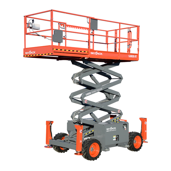
- Page 1 OPERATING MANUAL (CE) ROUGH TERRAIN SCISSORS MODELS SJ6826 RT SJ6832 RT 194125AG-A January 2018...
- Page 2 This manual is based on Serial Number(s): SJ 68XXRT 37 006 157 & Above Please refer to the website (www.skyjack.com) for older Serial Numbers. Skyjack Service Center Parts & Service (Europe) Unit 1 Maes Y Clawdd 3451 Swenson Ave. St. Charles,...
- Page 3 The Safety Alert Symbol identifies important safety messages on aerial platform, safety This Safety Alert Symbol means attention! signs in manuals or elsewhere. When you see this symbol, be alert to the possibility of Become alert! Your safety is involved. personal injury or death.
-
Page 4: Table Of Contents
Floor Loading Pressure ........................62 Table 4.6 EC Declaration of Conformity ......................64 Table 4.7 Maintenance and Inspection Schedule ...................65 Table 4.8 Operator’s Checklist ........................66 Section 5 - Labels ..........................67 Section 6 - Skyjack Features ........................ 90 Rough Terrain Scissors Page 4 December 2007... -
Page 5: Section 1 - About Your Aerial Platform
SKYJACK warrants each new SJRT Compact Series aerial platform to be free of defective parts and workmanship for the first 24 months. Any defective part will be replaced or repaired by your local SKYJACK dealer at no charge for parts or labor. Contact the SKYJACK Service Department for warranty statement extensions or exclusions. -
Page 6: Safety Rules
Common sense dictates the use of protective clothing when working on or near machinery. Use appropriate safety devices to protect your eyes, ears, hands, feet and body. Any modifications from the original design are strictly forbidden without written permission from SKYJACK. Electrocution Hazard This aerial platform is not electrically insulated. - Page 7 Section 1 - About Your Aerial Platform Safety Rules Safety Precautions Know and understand the safety precautions before going on to next section. WARNING Failure to heed the following safety • DO NOT increase the lateral precautions could result in tip over, surface area of the platform.
- Page 8 Safety Rules Section 1 - About Your Aerial Platform Safety Precautions (Continued) Know and understand the safety precautions before going on to next section. operate on surfaces not capable of • DO NOT holding the weight of the aerial platform including •...
- Page 9 • DO NOT place materials on the guardrails unevenly. or materials that exceed the confines of the guardrails unless approved by Skyjack. • STUNT driving and horseplay are prohibited. • DO NOT alter or disable limit switches or other safety devices.
- Page 10 If additional fall protection is required, platform that: by an employer or the authority having jurisdiction, Skyjack recommends the use of a fall restraint • does not appear to be working system to keep an occupant within the confines of properly.
-
Page 11: Section 2- Familiarization
Section 2- Familiarization SJRT Series 2.1 Familiarization of SJ68RT Series WARNING Aerial Platform Familiarization should be given only to individuals who are QUALIFIED And TRAINED to operate an aerial platform. Do not operate this aerial platform without proper authorization and training. Failure to avoid this hazard could result in death or serious injury. -
Page 12: Component Identification
Control Functions Section 2 - Familiarization 2.2 Component Identification 2.2-4 Load Sensing System This system is a safety device that prevents any normal The following descriptions are for identification, movement of the aerial platform from a stationary explanation and locating purposes only. working condition after the rated load is reached and exceeded. - Page 13 Section 2 - Familiarization Control Functions 2.2-5 Brake System Holding Valve Manual Override Knob - Located The brake system is located on the main manifold in on the holding valve at the bottom of each lift the hydraulic/fuel compartment. The brakes must be cylinder.
- Page 14 Control Functions Section 2 - Familiarization 2.2-9 Base Control Console Engine Start Pushbutton - This pushbutton “ ” The control console is located on the left side of the energizes the engine starter motor. engine compartment. It contains the following controls: Two Person Capacity Indicator Light (Model 6832)- Indicates “...
- Page 15 Section 2 - Familiarization Control Functions 2.2-10 Platform Control Console NOTE This removable control console is mounted at the right The engine start switch is interlocked with the front of the platform. It contains the following controls: oil pressure switch. If engine stalls or does not start immediately, this button will not work for a few seconds while oil pressure bleeds off.
-
Page 16: Visual & Daily Maintenance Inspections
Visual & Maintenance Inspection Section 2 - Familiarization Platform Control Console Scissor Platform Assembly Assembly Limit Switch Limit Switch Outriggers Outriggers Base Scissor Guard 2.3 Visual & Daily Maintenance 2.3-2 Electrical Maintaining the electrical components is essential to Inspections good performance and service life of the aerial platform. Begin the visual and daily maintenance inspections by checking each item in sequence for the conditions Inspect the following areas for chafed, corroded and... - Page 17 Section 2 - Familiarization Visual & Maintenance Inspection Muffler and Exhaust Engine Base Control Console Load/Tilt Sensor Engine Air Filter Main Power Disconnect Switch Radiator Hydraulic Pump Fuel Shut-off Valve Battery 2.3-5 Engine Compartment WARNING Ensure compartment latch is secure and Battery acid is extremely corrosive - in proper working order.
- Page 18 Visual & Maintenance Inspection Section 2 - Familiarization Muffler and Exhaust Engine Base Control Console Load/Tilt Sensor Engine Air Filter Main Power Disconnect Switch Radiator Hydraulic Pump Fuel Shut-off Valve Battery Ensure all bolts are properly tightened. Check oil level on dipstick Oil level should be in the “safe”...
- Page 19 Section 2 - Familiarization Visual & Maintenance Inspection Gear Type Hydraulic Oil Flow Divider Filter Oil Level Gauge Fuel Level Main Gauge Manifold Hydraulic Tank Fuel Tank 2.3-6 Hydraulic/Fuel Compartment • Fuel Tank Ensure compartment latch is secure and in proper working order. IMPORTANT Before using your aerial platform ensure •...
- Page 20 Visual & Maintenance Inspection Section 2 - Familiarization Gear Type Hydraulic Oil Flow Divider Filter Oil Level Gauge Fuel Level Main Gauge Manifold Hydraulic Tank Fuel Tank • Main Manifold Ensure all fittings and hoses are properly tightened and there is no evidence of hydraulic leakage.
- Page 21 Section 2 - Familiarization Visual & Maintenance Inspection Fall Protection Manuals Anchorage Platform Railing Platform Control Console AC Outlet Platform Assembly 2.3-7 Platform Assembly • AC Outlet on Platform Ensure outlet has no visible damage and free from dirt or obstructions. WARNING •...
- Page 22 Visual & Maintenance Inspection Section 2 - Familiarization Maintenance Lift Cylinder Support Limit Switch Scissor Bumper Scissor Guard Roller Scissor Assembly 2.3-8 Lifting Mechanism • Lift Cylinder(s) Ensure each lift cylinder is properly 1. Raise the platform (refer to Section 3.8-4) until secured, there are no loose or missing there is adequate clearance to swing down the...
- Page 23 Therefore, replace tires only with the exact Skyjack- approved type. Failure to operate with matched approved tires in good condition may result in death or serious injury.
- Page 24 Visual & Maintenance Inspection Section 2 - Familiarization Overhead View Steer Cylinder Assembly Base Weldment Splitter Manifold Wheel/Tire Assembly Tie Rod Emergency Lowering Access Rod • Steer Cylinder Assembly • Tie Rod Ensure steer cylinder assembly is Ensure there are no loose or missing properly secured, there are no loose parts, tie rod end studs are locked and or missing parts, all fittings and hoses...
-
Page 25: Function Tests
Section 2 - Familiarization Function Tests Emergency Stop Button Platform/Engine/Base Key Switch Main Power Disconnect Switch 2.4 Function Tests 2.4-2 Base Control Console Function tests are designed to discover any malfunctions before aerial platform is put into service. The operator WARNING must understand and follow step-by-step instructions Ensure that you maintain three points of... - Page 26 Function Tests Section 2 - Familiarization Emergency Stop Button Freewheel Valve Platform/Engine/Base Key Switch Brake Hand Brake Auto Pump Reset Valve Emergency Base Control Console Lowering Valve Main Power Disconnect Switch Main Manifold • Test Platform/Engine/Base Key Switch • Test Platform Raise/Lower Switch 1.
- Page 27 Section 2 - Familiarization Function Tests Lift/Drive/Steer Enable Low/High Throttle Trigger Switch Switch Lift/Drive/Steer Controller Glow Plug (Diesel) Free-wheeling Torque Switch Switch Valve Brake Auto Brake Hand Reset Valve Pump Lift/Drive Switch Engine Start Emergency Switch Lowering Valve Horn Pushbutton Emergency Stop Main Manifold Button...
- Page 28 Function Tests Section 2 - Familiarization Rocker Switch Lift/Drive/Steer Enable Trigger Switch Low/High Throttle Lift/Drive/Steer Switch Controller Glow Plug (Diesel) Switch Torque Switch Lift/Drive Switch Emergency Stop Button Engine Start Switch Horn Pushbutton • Test Platform Raising/Lowering • Test Steering 1.
- Page 29 Section 2 - Familiarization Function Tests Rocker Switch Lift/Drive/Steer Enable Trigger Switch Low/High Throttle Lift/Drive/Steer Switch Controller Glow Plug (Diesel) Switch Torque Switch Lift/Drive Switch Emergency Stop Button Engine Start Switch Horn Pushbutton • Test Speed Limit Result: Aerial platform should come to a stop.
- Page 30 Function Tests Section 2 - Familiarization Dual Capacity Control Console (Model 6832) Two Person Capacity Indicator Light Platform Capacity Selector Switch • Test Platform Capacity Selector 4. Lift and select “ ” two person platform Switch (Model 6832) capacity from platform capacity selector switch.
- Page 31 Section 2 - Familiarization Function Tests Left-Rear Left-Front Platform Control Console Right-Rear Right-Front • Test Hydraulic Outriggers (If Equipped) 7. Drive the aerial platform to maximum (For Hydraulic Outrigger Operation, refer to speed. Section 3.8-9) Result: Aerial platform drives at high speed.
- Page 32 Function Tests Section 2 - Familiarization Left-Rear Left-Front Platform Control Console Right-Rear Right-Front Attempt to partially extend Right-Rear Result: Lift function will not operate. Outrigger (approximately 4”). Result: Outrigger will not extend. With Left-Rear Outrigger partially extended, attempt to lift the platform. Attempt to partially extend Left-Rear Result: Lift function will not operate.
- Page 33 Section 2 - Familiarization Function Tests Left-Rear Left-Front Platform Control Console Right-Rear Right-Front 16. Platform at stowed position. 18. Extend all four outriggers until all tires are Extend each outrigger until it raises the off the ground and the aerial platform is tires up approximately 2”.
-
Page 34: Winching And Towing Procedure
Procedures Section 2 - Familiarization 2.5 Winching and Towing Procedure 2.5-1 To Release the Free-wheeling Valve This section provides the operator with procedure about Ensure aerial platform is on level ground. Chock winching and towing and how to release the brakes. or block the wheels to prevent aerial platform from rolling. - Page 35 Section 2 - Familiarization Procedures 2.5-2 To Release the Brakes Manually Chock or block wheels to prevent aerial platform from rolling. WARNING Reengage brakes by pulling out brake auto reset Do not manually disengage brakes if the valve plunger. aerial platform is on a slope. Figure 2-9.
-
Page 36: Emergency Lowering Procedure
Procedures Section 2 - Familiarization 2.6 Emergency Lowering Procedure This section guides the operator on how to use emergency lowering system. This system allows platform lowering in the event of an emergency or an engine malfunction. WARNING Keep clear of scissors mechanism when using emergency lowering valve. -
Page 37: Section 3 - Operation
Section 3 - Operation General 3.0 Operation • The operator must be sure that the aerial platform This section provides the necessary information needed has been properly maintained and inspected to operate the aerial platform. It is important that the user before using it. -
Page 38: Major Components
Section 3 - Operation 3.2 Major Components Entry Gate Platform Control Console Manual Storage Box Main Platform Extension Platform Lifting Mechanism Hydraulic Compartment Scissor Guard Engine Base Compartment Outrigger SKYJACK Model SJ 6832RT Aerial Platform Rough Terrain Scissors Page 38 December 2007... -
Page 39: Major Assemblies
Section 3 - Operation Major Assemblies 3.3 Major Assemblies 3.4 Serial Number Nameplate The aerial platform consists of three major assemblies: The serial number nameplate, located at the rear of the base, lifting mechanism and platform. aerial platform, lists the following: •... -
Page 40: Component Identification
Component Identification Operation - Section 3 3.5 Component Identification 3.5-2 Manual Storage Box This weather-resistant box is mounted on the platform The following descriptions are for identification, railings. It contains the operating explanation and locating purposes only. manual, EC declaration and other important documentation. - Page 41 Section 3 - Operation Component Identification 3.5-3 Folding Guardrail System WARNING This system, when folded down, reduces the height Before operating this aerial platform of the retracted aerial platform for transporting and check the guardrail system for loose traveling through doorways only. Refer to Section 3.10 or missing locking pins.
-
Page 42: Component Identification (Optional Equipment/Attachments)
Component Identification (Special Options) Operation - Section 3 3.6 Component Identification Leveling Indicator Light - This light illuminates to display the status of the outriggers when the (Optional Equipment/Attachments) auto and manual level functions are in use. The This section describes the components that are optional indicator light has the following states: to aerial platforms. -
Page 43: Operator's Responsibility
Section 3 - Operation Operator’s Responsibility 3.7 Operator’s Responsibility Repairs to the aerial platform may only be made by a qualified service technician. After repairs are completed, It is the responsibility of the operator, prior to each work the operator must perform visual and daily maintenance shift, to perform the following: inspections &... -
Page 44: Start Operation
Start Operation Section 3 - Operation 3.8 Start Operation WARNING Carefully read and completely understand the operating An operator should not use any aerial manual and all warnings and instruction labels (refer to platform that: Section 5 - Labels) on the aerial platform. •... - Page 45 Section 3 - Operation Start Operation 3.8-1 To Activate Base Control Console NOTE Choke is only active while button is depressed. Occasional use of choke WARNING button may be necessary during the first Ensure that you maintain three points of few seconds of engine operation.
- Page 46 Start Operation Section 3 - Operation 3.8-3 To Activate Platform Control Console WARNING Do not lower the platform unless the Turn main power disconnect switch to “ ”on area below is clear of personnel and position. obstructions. On the base control console, pull out the “ ”...
- Page 47 Section 3 - Operation Start Operation 3.8-5 To Drive Forward or Backward 3.8-6 To Steer Activate platform controls (refer to Section 3.8-3). WARNING Be aware of blind spots when operating On the platform control console, turn lift/drive the aerial platform. switch to “...
- Page 48 Start Operation Section 3 - Operation 3.8-7 To Select Drive Torque 3.8-8 To Extend or Retract Manual Extension Platform High Torque: Select high torque when climbing grades, traveling on rough terrain or when loading or unloading aerial platform. To activate high torque, select torque switch to “...
- Page 49 Section 3 - Operation Start Operation 3.8-9 Hydraulic Outriggers (If Equipped) Ensure each outrigger pad is in firm contact over These devices are mounted to four corners of the base. its entire surface area, with a suitable supporting When properly positioned, they increase the stability of surface! Make adjustments if necessary using the aerial platform.
- Page 50 Start Operation Section 3 - Operation 3.8-10 Generator (If Equipped) 3.8-11 Shutdown Procedure To start generator: Completely lower the platform. On platform control console, select lift/drive switch On platform control console, push in “ ” emergency stop button. to “ ”...
-
Page 51: Loading/Unloading
The transport vehicle must be parked on a level surface and must be secured to prevent rolling while aerial platform is being loaded/unloaded. 3.9-1 Lifting When it is necessary to lift the Skyjack aerial platform the following conditions must be met: • The platform must be fully lowered. •... - Page 52 Loading/Unloading Section 3 - Operation NOTE Lift with forks in designated forklift lifting locations as illustrated in Figure 3-8. Forklift Lifting Locations (aerial Forklift Lifting Locations platforms with no outriggers) Figure 3-8. Forklift Lifting Locations 3.9-2 Driving When driving the aerial platform: •...
- Page 53 Notes Rough Terrain Scissors December 2007 Page 53...
-
Page 54: Guardrail Folding Procedure
Guardrail Folding Procedure Section 3 - Operation 3.10 Guardrail Folding Procedure To fold the guardrail system down: When folded down, the folding guardrail system reduces Ensure aerial platform is on level ground. the height of the retracted aerial platform for transporting only. - Page 55 Section 3 - Operation Guardrail Folding Procedure Remove all the locking pins on the left side WARNING guardrail and fold it down. Any lowered guardrail will create a fall hazard. Remain away from the sides of With the gate closed, remove all the locking the platform while raising or lowering the pins on the entrance side guardrail and fold the guardrails to avoid falling.
-
Page 56: Moving The Aerial Platform Through A Doorway
Moving the Aerial Platform Through a Doorway Section 3 - Operation 3.11 Moving the Aerial Platform through Ensure there are no personnel in the intended path of travel. a Doorway Notify those around the pathway that you will be WARNING moving the aerial platform. - Page 57 Section 3 - Operation Moving the Aerial Platform Through a Doorway Disconnect platform control console and return it to the platform. WARNING Ensure that you maintain three points of contact when using the ladder to mount/ dismount platform. Return guardrails to upright position if folded. Refer Section 3.10 for guardrail folding procedure.
-
Page 58: Maintenance Support Procedure
Maintenance Support Procedure Section 3 - Operation 3.12 Maintenance Support Procedure To Store the Maintenance Support Turn main power disconnect switch to “ ”on position. Raise platform until there is adequate clearance to swing up the maintenance support. Swing bar up into storage bracket. Lower the platform. -
Page 59: Section 4 - Tables
Section 4 Tables Table 4.1 Standard and Optional Features Compact RT's MODEL 6826 6832 S T A N D A R D E Q U I P M E N T Joystick control 18.5 kW (24.8 hp) Kubota D902 diesel water-cooled engine Easy operation 152 cm roll out extension platform Load sensing system Lowering warning system... - Page 60 Tables Section 4 Table 4.2 Specifications and Features Compact RT’s Model 6826 6832 3500 kg 3770 kg With Outriggers Width 1.77 m 1.77 m 3.35 m 3.35 m With Outriggers Platform Size 1.4 m x 2.4 m 1.4 m x 2.4 m 9.8 m 11.6 m Working...
- Page 61 Section 4 Tables Table 4.3 Owner’s Annual Inspection Record Model Number: _________________ Serial Number:__________________ 20__ 20__ 20__ 20__ 20__ 20__ 20__ 20__ 20__ 1001AB This decal is located on the scissor assembly. It must be completed after an annual inspection has been completed. Do not use the aerial platform if an inspection has not been recorded in the last 6 months.
-
Page 62: Floor Loading Pressure
Tables Section 4 Table 4.5 Floor Loading Pressure Total Aerial Total Aerial Platform Load Platform Wheel/ MODEL LCP** OUP** Weight Outrigger Pad kg/m min* 3500 1400 1122 6826 on Tires max* 4067 1635 1310 min* 3500 1400 6826 on Outrigger Pads max* 4067 1635... - Page 63 Intermixing tires of different types or using tires of types other than those originally supplied with this equipment can adversely affect stability. Therefore, replace tires only with the exact Skyjack- approved type. Failure to operate with matched approved tires in good condition may result in death or serious injury.
-
Page 64: Ec Declaration Of Conformity
Tables Section 4 Table 4.6 EC Declaration of Conformity EC Declaration of Conformity We, SKYJACK INC., declare under our sole responsibility that the product Mobile Elevating Work Platform Model number: [*] Serial number: [*] to which this declaration relates is in conformity with the following directives:... - Page 65 B - Perform Scheduled Maintenance Inspection. Refer to Service & Maintenance manual. * - Maintenance must be performed only by trained and competent personnel who are familiar with mechanical procedures. † - Refer to Skyjack's website @ www.skyjack.com for latest service bulletins proior to performing quarterly or yearly inspection. WARNING Use original or manufacturer-approved parts and components for aerial platform.
-
Page 66: Operator's Checklist
Model: Hourmeter Reading: Operator's Name (Printed): Date: Time: Operator's Signature: Each item shall be inspected using the appropriate section of the Skyjack operating manual. As each item is inspected, check the appropriate box. - PASS DAILY - FAIL FREQUENTLY ... -
Page 67: Section 5 - Labels
Section 5 - Labels Label Legend Label Legend Safety Red Safety Red indicates DANGER. Safety Orange Safety Orange indicates WARNING. Safety Yellow Safety Yellow indicates CAUTION. Safety Green Safety Green indicates emergency lowering. Safety Blue Safety Blue indicates safety information. Rough Terrain Scissors December 2007 Page 67... - Page 68 Labels Section 5 Labels - Models 6826 & 6832 Engine Panel Label Pictorial Description Electrical Panel (Model 6826) Push “ ” to reset ground circuit breaker. Push “ ” to reset power circuit breaker. Push “ ” to stop engine and disable controls (Emergency Stop). Light indicates controls enabled.
- Page 69 Section 5 Labels Labels - Models 6826 & 6832 Engine Panel Label Pictorial Description Electrical Panel (Model 6832) Push “ ” to reset ground circuit breaker. Push “ ” to reset power circuit breaker. Push “ ” to stop engine and disable controls (Emergency Stop). Light indicates controls enabled.
- Page 70 Labels Section 5 Labels - Models 6826 & 6832 Engine Panel (Continued) Label Pictorial Description Main Power Disconnect Main power disconnect switch Battery Fuse Assembly Assemble fuse as shown. Torque to value indicated. Rough Terrain Scissors Page 70 December 2007...
- Page 71 Rules. Read and understand the outlined risks associated with this work platform prior to operation. Manual Storage Box Indicates location of operating manual. Skyjack Logo Skyjack Model Number* Product Identifier *Model number will vary, may not be as shown. Caution Tape Stripe...
- Page 72 Labels Section 5 Labels - Models 6826 & 6832 Right Side (Continued) Label Pictorial Description Keep Clear Keep clear. Stay away from aerial platform when in operation. Annual Inspection Ensure that work platform has received annual inspection prior to operation. Model Number* Product Identifier *Model number will vary, may not be as shown.
- Page 73 Section 5 Labels Labels - Models 6826 & 6832 Right Side (Continued) 128742AA Top View 128226AA 13 12 11 Label Pictorial Description Foam-filled Tire Indicates foam-filled tire only. Wheel Specifications Refer to manual for wheel type, offset, pressure and torque. Wheel Load Indicates rated wheel load.
- Page 74 Labels Section 5 Labels - Models 6826 & 6832 Front Side Top View Label Pictorial Description Skyjack Logo Skyjack Caution Tape Stripe Caution stripe Serial Plate Product identification and specifications ...
- Page 75 Section 5 Labels Labels - Models 6826 & 6832 Front Side (Continued) Top View Label Pictorial Description Lift and Tie Down Points Only use these points for lifting or tying down. How to engage maintenance support for inspection or maintenance. Refer to Operating manual. 1.
- Page 76 Labels Section 5 Labels - Models 6826 & 6832 Left Side 128226AA Label Pictorial Description Skyjack Logo Skyjack Model Number* Product Identifier *Model number will vary, may not be as shown. Caution Tape Stripe Caution stripe Keep Clear Keep clear. Stay away from aerial platform when in operation.
- Page 77 Section 5 Labels Labels - Models 6826 & 6832 Left Side (Continued) Label Pictorial Description Model Number* Product Identifier *Model number will vary, may not be as shown. Connect AC Supply Connect AC supply here. “CE” CE rating mark Sound Power Level Guaranteed maximum sound power level Rough Terrain Scissors December 2007...
- Page 78 Labels Section 5 Labels - Models 6826 & 6832 Left Side (Continued) 128226AA Label Pictorial Description Winching/Towing/Pushing Procedure Refer to Operating manual. 1. Block or chock wheels to prevent aerial platform from rolling. 2. Turn main power disconnect switch to off position. 3.
- Page 79 Section 5 Labels Labels - Models 6826 & 6832 Left Side (Continued) Top View 128226AA Label Pictorial Description Foam-filled Tire Indicates foam-filled tire only. Wheel Specifications Refer to manual for wheel type, offset, pressure and torque. Wheel Load Indicates rated wheel load. Forklift Lifting Location Insert fork fully into forklift lifting location to lift aerial platform.
- Page 80 Labels Section 5 Labels - Models 6826 & 6832 Hydraulic/Fuel Compartment Label Pictorial Description Hydraulic Oil ATF Dexron III Replace hydraulic fluid with ATF Dexron III only. Diesel Use diesel fuel only. No Smoking Do not smoke near this location. Rough Terrain Scissors Page 80 December 2007...
- Page 81 Section 5 Labels Labels - Models 6826 & 6832 Back Side Top View 102896AC 102896AC 124767AB Label Pictorial Description Operator’s Daily Inspection. Refer to the Operating manual. Perform visual inspection and function tests at the beginning of each shift. Refer to Section 4: Maintenance and Inspection Schedule.
- Page 82 Labels Section 5 Labels - Models 6826 & 6832 Platform View Label Pictorial Description Platform Capacity Platform capacity label for 6826RT. Rated work load in each configuration is as shown. Rated work load includes the weight of both personnel and material. Maximum number of people in each configuration is as shown.
- Page 83 Section 5 Labels Labels - Models 6826 & 6832 Platform Control Console Label Pictorial Description Platform Control Console Squeeze “ ” trigger to enable controller. Operate “ ” rocker switch to steer. Move controller forward “ ” to raise or backward “ ”...
- Page 84 Labels Section 5 Labels - Models 6826 & 6832 Dual Capacity Control Console (Model 6832) Label Pictorial Description Dual Capacity Control Console (Model 6832) Lift and select either “ ” four person or “ ” two person platform capacity. Light “ ”...
- Page 85 Section 5 Labels Labels - Models 6826 & 6832 Lift Cylinders Label Pictorial Description Orifice Installed Orifice installation warning Emergency Lowering Procedure Refer to Operating manual. 1. Turn main power disconnect switch to off position. 2. To open the lift cylinder holding valves located at the bottom of each cylinder: if higher reach required, use emergency lowering rod located on the top of the base to:...
- Page 86 Labels Section 5 Labels - Models 6826 & 6832 - Options and Attachments Outriggers Label Pictorial Description Keep Clear Keep clear. Stay away from aerial platform when in operation. Crushing Hazard Danger - Crushing hazard Warning - Do Not Alter Do not alter or disable limit switches or other safety devices.
- Page 87 Section 5 Labels Labels - Models 6826 & 6832 - Options and Attachments Outrigger Control Console Label Pictorial Description Manual Outrigger Control Console with Generator Select “ ” retract or “ ” extend for each outrigger. Select “ ” to enable or “ ”...
- Page 88 Labels Section 5 Labels - Models 6826 & 6832 - Options and Attachments Air Supply and Inverter Options Label Pictorial Description Connect Air Supply Connect platform air supply here. Fuse Fuse location Rough Terrain Scissors Page 88 December 2007...
- Page 89 Notes Rough Terrain Scissors December 2007 Page 89...
-
Page 90: Section 6 - Skyjack Features
Skyjack Features Section 6 6.0 Skyjack Features Your Skyjack machine may be equipped with the following features: At the heart of every Skyjack machine, proven and simplistic control systems using Skyjack’s colour coded and numbered wiring system make our machines the easiest to trouble shoot and repair. - Page 92 www.skyjack.com...
Need help?
Do you have a question about the SJ68RT Series and is the answer not in the manual?
Questions and answers