Table of Contents
Advertisement
Quick Links
testo Saveris radio data logger
0572 2200 XX Gateway
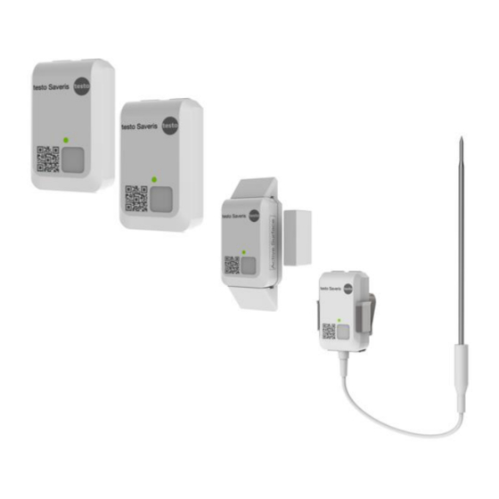
0572 2201 XX radio data logger – ambient temperature
0572 2202 XX radio data logger – temperature product simulation
0572 2203 XX radio data logger – door contact
0572 2204 CC radio data logger – core temperature
Instruction manual for NSF testing
V2
Advertisement
Table of Contents

Subscribe to Our Youtube Channel
Related Manuals for TESTO 0572 2200 Series


Summary of Contents for TESTO 0572 2200 Series
- Page 1 Saveris radio data logger 0572 2200 XX Gateway 0572 2201 XX radio data logger – ambient temperature 0572 2202 XX radio data logger – temperature product simulation 0572 2203 XX radio data logger – door contact 0572 2204 CC radio data logger – core temperature...
-
Page 2: Table Of Contents
1 About this document ................... 2 1.1 Usage ..................... 2 1.2 Symbols ....................2 2 Safety and disposal ..................3 Take the testo information document into account (accompanies the product)....................3 2.1 Warning ....................3 3 System description ..................3 3.1 System Overview ................... - Page 3 Table of contents 5.4 Disable of radio data sensor or Gateway ..........20 6 Battery / Sensor power supply ..............21 6.1 Lithium battery ..................21 6.2 Modified sensors for power supply test ..........21 7 Technical data .................... 22 7.1 Radio specific data ................
-
Page 4: About This Document
1 About this document Read these operating instructions carefully and familiarize yourself with the product before using it 1.1 Usage • Keep this documentation to hand so that you can refer to it when necessary. • Please read this instruction manual through carefully and familiarize yourself with the product before putting it to use. -
Page 5: Safety And Disposal
Indicates possible property damage 3 System description The testo Saveris wireless sensors are part of the testo Saveris Solution. As a stationary measurement technology solution, they are ideally suited for monitoring temperature and door contacts in cold stores and warehouses. The wireless sensors are available in various versions and can therefore be flexibly adapted for numerous applications. - Page 6 The sensors can be integrated into the testo Saveris Food Solution. The data is recorded at configurable intervals and transferred to the Testo Cloud [Cloud] at configurable intervals. The customer's WLAN or Ethernet infrastructure is a prerequisite for transmitting the data (not part of the scope of delivery). The measured values stored in the cloud can be called up and analyzed at any time in the corresponding testo Saveris Cockpit [Webbased analysis].
-
Page 7: System Overview
3.1 System Overview 3.2 Product description 1 article number & name: 0572 2201 XX description: radio data logger – ambient temperature 2 article number & name 0572 2202 XX description: radio data logger – temperature product simulation... - Page 8 3 article number & name 0572 2203 XX description: radio data logger – door contact 4 article number & name 0572 2204 XX description: radio data logger – core temperature 5 article number & name 0572 2204 XX description: Gateway 6 article number &...
-
Page 9: Radio Data Logger - Ambient Temperature
3.3 radio data logger – ambient temperature This sensor measures temperature of its ambient. 3.4 radio data logger – temperature product simulation This sensor measures temperature of its ambient as well but provides an additional calculated temperature measurement value. This calculated value represents a product temperature value according a calculated/ simulated behavior. -
Page 10: Gateway Button Functions & Led
3.7 Gateway button functions & LED long = 1 sec / periode = 2 sec short = 200 msec / periode = 400msec Gateway LED1 Sensor status Mode action / Signal Color button Join Mode button press < continuously green 3 sec new sensor was connected ----... -
Page 11: Radio Data Logger Button Functions & Led
3.8 Radio data logger button functions & Mode action / button Signal Power down button press < 3 Blinking for 90 sec 0,2 sec on 0,8 Sensor switched ON sec in state OFF sec off (green) -> sensor is in from power down manual join mode In case of finished join mode (max... -
Page 12: Commissioning
4 Commissioning This chapter describes the commissioning of the NSF test set up. The system is mainly designed to enable NSF to do the certification tests. The system does not support the whole system UI functionality, which will be offered to end customers in series. The hardware devices have already achieved nearly series level. -
Page 13: Wlan Module And Poe Module
4.2.1 WLAN module and PoE module Before connecting the gateway to the PC or to power supply, the communication modules must be mounted to the gateway first. -
Page 14: Power Supply / Batteries
4.3.1 Account / Saveris Connect Key The Account ID/Saveris Connect Key is the unique address of your user account in the Testo cloud. This connect key is needed to configure the Gateway in order to ensure that the Gateway sends your data to the correct user account. -
Page 15: Gateway Offline Configuration
4.3.3 Gateway offline configuration The Gateway can be configured via a PDF form. Note You need the Adobe Reader program (version 10 or later) to use the PDF form correctly. If you have not installed Adobe Reader, you can go to the following address to download it free of charge: http://get.adobe.com/reader/. -
Page 17: Connecting A Radio Data Logger
4.4 Connecting a radio data logger Before you connect a radio data logger to Gateway, please ensure, that the Gateway is connected to the cloud. You can check the with Saveris Restaurant Website. See chapter 5! 1. Press the button on the Gateway <3 sec. -> Sensor LED is on and Gateway is in connect/ join mode! 2. -
Page 18: Software
5 Software 5.1 Saveris Restaurant Software To get access use following URL-address https://i.food.saveris.net 5.1.1 Access Please enter your assigned account e-mail-address and password! -
Page 19: Saveris Restaurant Online/ Radio Data Logger Website
5.1.2 Saveris Restaurant Online/ Radio data logger website By selecting the Online data logger page, you get to the radio data logger and dashboard. 5.1.3 Measurement curves Measurement curves can be displayed by pressing the three dots or select page stationary measurements in the Analysis field... -
Page 20: Mts Viewer Software Url-Address
In this account you can only display the data. To be able to export the data, you must switch to the MTS View Software! 5.2 MTS Viewer Software URL-address To get access use following URL-address MTS Viewer (saveris.net) -
Page 21: Mts-Viewer Dashboard
Please enter your assigned account e-mail-address and password! It is not possible to display Saveris Restaurant Account and MTS viewer of one account in parallel. 5.3 MTS-Viewer dashboard 5.3.1 Selecting Sensor Before displaying the measurement values, the relevant sensors must be selected. -
Page 22: Csv Export
5.4 Disable of radio data sensor or Gateway If a Gateway or sensor is connected to the cloud, the disconnecting of a sensor or gateway has to be done manually by Testo R&D team. Testo SE & Co. KGaA Celciusstraße 2... -
Page 23: Battery / Sensor Power Supply
6 Battery / Sensor power supply 6.1 Lithium battery The sensor has a Lithium battery, which cannot be exchanged by customer. If battery is empty, the sensor must be replaced. 6.2 Modified sensors for power supply test To perform VCC tests Test provides modified sensors. Battery is assembled inside but not connected to PCBA. -
Page 24: Technical Data
7 Technical data Messspezifische Daten Sensor 0572 2201-xx 0572 2202-xx 0572 2203-xx 0572 2204-xx Sensor type Ambient temperature Door contact Core probe temperature product sensor Sensor sensor simulation measurement -30...+85 °C -30...+85 °C ---- range accuracy ± 0,5 °C ± 0,5 °C ±... -
Page 25: Technical Specifications For Wlan Or Ethernet Communication
For Ethernet communication please use DHCP configuration in your IT- infrastructure. 7.2.2 Ports Ports The testo Saveris Gateway use the MQTT protocol, which communicates via the TCP 1883 and 8883 port. Furthermore, these UDP port shares are necessary: - Port 53 (DNS name resolution) - Page 26 Sensors 0572 2201- 0572 2202-xx 0572 2203-xx 0572 2204-xx Internal Sensor External Sensor Gateway 0572 2200 xx Operating 0°C ...+50°C temperature 40°C … +60°C Storage temperature Protection IP 67 with connected WLAN communication module class IP 20 with connected Ethernet communication module Memory none Power supply...
- Page 27 The EU Declaration of Conformity can be Shielded cables should be used for a composite interface. This is to ensure continued protection against radio frequency interference. found on the testo homepage www.testo.com under the product specific downloads. FCC warning statement...
Need help?
Do you have a question about the 0572 2200 Series and is the answer not in the manual?
Questions and answers