
Related Manuals for Vortice VORT ARTIK UI


Summary of Contents for Vortice VORT ARTIK UI
- Page 1 Libretto istruzioni Instruction booklet VORT ARTIK COD. 5.471.084.713 17/07/2017...
-
Page 2: Table Of Contents
ndice Informazioni sull'utilizzo Precauzioni........................1 Nomi delle parti......................5 Guida operativa Guida operativa......................6 Telecomando......................7 Tasti del telecomando....................8 Richiesta indirizzo unità interna................14 Manutenzione Pulizia e manutenzione....................14 Malfunzionamenti Analisi dei malfunzionamenti..................16 Informazioni sull'installazione Disegno d’installazione....................19 Preparativi per l’installazione..................20 Installazione Installazione dell’unità interna................21 Controlli dopo l’installazione..............Funzionamento di prova..................27 IN ALCUNI PAESI DELL'UNIONE EUROPEA QUESTO PRODOTTO NON RICADE NEL CAMPO DI APPLICAZIONE DELLA LEGGE NAZIONALE DI RECEPIMENTO DELLA DIRETTIVA RAEE E... -
Page 3: Precauzioni
• Non usare questo prodotto per una funzione differente da quella esposta in questo libretto. • Dopo aver tolto il prodotto dal suo imballo, assicurarsi della sua integrità: nel dubbio rivolgersi subito all’Assistenza Tecnica Vortice. • L’uso di qualsiasi apparecchio elettrico comporta l’osservanza di alcune regole fondamentali, tra le quali: non toccarlo con mani bagnate o umide;... - Page 4 Contattare sempre l’Assistenza Tecnica Vortice. • L’esposizione diretta e prolungata di persone, animali o piante al flusso d’aria in uscita dall’unità interna del climatizzatore può essere...
- Page 5 In caso di imperfezioni evitarne l’utilizzo e contattare subito l’Assistenza Tecnica Vortice. • Accertarsi periodicamente delle buone condizioni di conservazione delle staffe dell’unità interna, se presenti. • Non appoggiare oggetti pesanti sul cavo di alimentazione e prestare attenzione a che esso non venga compresso.
- Page 6 Precauzioni • Disconnettere l’apparecchio dalla rete elettrica prima di eseguire manutenzioni. • Non lavare la macchina con getti d’acqua diretti o in pressione. • I dati elettrici della rete devono corrispondere a quelli riportati nella targa dati. Intervallo di temperatura di esercizio Lato interno DB/WB (°C) Lato esterno DB/WB (°C) Raffreddamento...
-
Page 7: Nomi Delle Parti
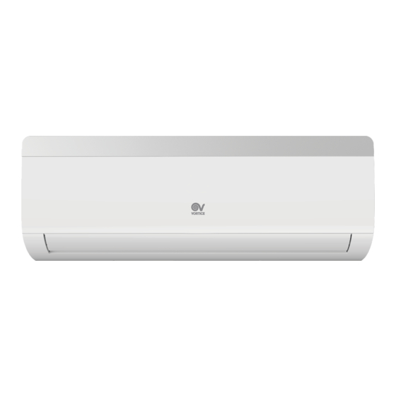
Nome delle parti Unità interna Pannello Panello Ingresso aria Aletta orizzontale Filtro Uscita aria Pulsante AUX Display Telecomando Per alcuni modelli: Indicatore della temperatura Indicatore della temperatura Spia Wi-Fi Per alcuni modelli: Indicatore della temperatura Spia Wi-Fi NOTA: Il prodotto effettivo potrebbe differire da quello illustrato; fare sempre riferimento al prodotto effettivo. -
Page 8: Guida Operativa
Guida operativa Installazione batterie 1. Premere la parte posteriore del telecomando contrassegnata dal simbolo “ ”,come mostrato nella figura, e spingere il coperchio del vano batterie lungo la direzione indicata dalla freccia. 2. Installare due pile a secco di tipo AAA da 15 V e assicurarsi che i poli “+” e “-” siano nella posizione corretta. -
Page 9: Telecomando
Telecomando Velocità ventilatore impostata I Feel I feel Segnale Wi-Fi Modalità Turbo Modalità Quiet Modalità automatica Display numerico Modalità Clean Display numerico Modalità raffreddamento Funzione Health Modalità deumidificazione Modalità ECO Modalità ventilazione Modalità Sleep Modalità riscaldamento Blocco bambini Oscillazione a destra e a sinistra Orario Simbolo temperatura Illuminazione... -
Page 10: Tasti Del Telecomando
Tasti del telecomando Dopo aver premuto il tasto di accensione, il condizionatore emetterà un suono. L’indicatore di alimentazione mostrerà la dicitura ON. A questo punto sarà possibile gestire il condizionatore tramite il telecomando. Una volta acceso, quando si preme un tasto del tele- comando, il display mostra l'icona corrispondente della funzione impostata. - Page 11 Tasti del telecomando Tasto FAN Premere questo tasto per impostare la velocità del ventilatore (continuare a premerlo per passare da una velocità all’altra: auto (AUTO), fan1( ), fan2 ( ), fan3 ( ), fan4 ( ), fan5 ), velocità continua. AUTO fan1 fan2...
- Page 12 Tasti del telecomando Tasti + e - Premere i tasti “+” e “-” per aumentare o diminuire di 1°C la temperatura impostata. Tenere premuti i tasti “+” o “-” per modificare velocemente la temperatura impostata sul telecomando. Rilasciando il tasto dopo aver completato l’operazione, l’indicatore della temperatura sull’unità interna cambierà di conseguenza.
- Page 13 Tasti del telecomando Tasto I FEEL Premere questo tasto per attivare la funzione I FEEL; verrà visualizzata l’icona “ ” sul display del telecomando. L’attivazione della funzione I FEEL comporta il cambio del punto di rilevazione della tempe- ratura nell’ambiente domestico: la temperatura non viene piu rilevata a bordo del condizio- natore (come preimpostato dal produttore), ma viene rilevata da un sensore posto all’interno del telecomando.
- Page 14 Tasti del telecomando Premere i tasti “+” o “-” per impostare la decina dei minuti. Se si preme questo tasto un’altra volta, sul telecomando lampeggeranno le icone “ON” e “ ”. Premere i tasti “+” o “-” per impostare il numero dei minuti. Se si tengono premuti i tasti “+” o “-”, il valore cambierà velo- cemente fino a raggiungere quello desiderato.
- Page 15 Tasti del telecomando Tasto Premere questo tasto per accendere o spegnere la funzione SMART; per ulteriori dettagli, fare riferimento alla documentazione dedicata alla APP o al sito www.vortice.it. Inserimento funzioni pulsanti combinazione Funzione blocco bambini Premere contemporaneamente “+” e “-” per attivare o disattivare la funzione blocco bambini.
-
Page 16: Richiesta Indirizzo Unità Interna
Richiesta indirizzo unità interna In caso di uso congiunto con un’unità esterna multi, se una unità presenta malfunzionamenti e risulta necessario rivolgersi all’ assistenza, comportarsi come segue: Puntare il telecomando verso l’unità interna, premere contemporaneamente i tasti “Light” e “- ”... - Page 17 Pulizia e manutenzione Pulizia del filtro Montare il filtro Pulire il filtro servendosi di un Montare il filtro e chiudere ferma- aspirapolvere o di acqua. Usare mente il pannello di copertura. l’acqua quando il filtro è estrema- mente sporco (a meno di 45 °C) e lasciarlo asciugare in un luogo fresco e protetto dalla luce del sole.
-
Page 18: Analisi Dei Malfunzionamenti
Analisi dei malfunzionamenti Analisi dei fenomeni generali Controllare i seguenti aspetti prima di contattare l’addetto alla manutenzione. Se non è pos- sibile risolvere il malfunzionamento, contattare il rivenditore locale o un professionista. Fenomeno Aspetti da controllare Soluzione Ci sono forti interferenze (come Staccare la spina. - Page 19 Analisi dei malfunzionamenti L’aria dell’ambiente interno si è raffreddata velocemente. Dopo al- cuni minuti la temperatura e l’umi- dità interne diminuiranno e l’acqua nebulizzata scomparirà. E’ stata richiesta una temperatura al di fuori dell’intervallo possibile? Ci sono Si sente rumore di acqua che “scorre”...
- Page 20 Analisi dei malfunzionamenti Codice Errore Quando lo stato del condizionatore è anomalo, la spia della temperatura dell’unità interna lampeggerà mostrando il codice d’errore corrispondente. Fare riferimento alla seguente lista per identificare il codice d’errore. I codici d’errore riportati di seguito sono solo una parte. Codice Problema Soluzione...
-
Page 21: Disegno D'installazione
Disegno d’installazione Distanza dal muro Almeno 15cm Almeno 15cm Distanza dal muro... -
Page 22: Preparativi Per L'installazione
Preparativi per l’installazione Strumenti 1 Indicatore di livello 2 Cacciavite 3 Trapano a percussione 4 Testa di perforazione 5 Espansore per tubi 6 Chiave dinamometrica 7 Chiave aperta 8 Tagliatubi 9 Rilevatore di perdite 10 Pompa da vuoto 11 Misuratore di pressione 12 Misuratore universale 13 Chiave a brugola 14 Metro a nastro Precauzioni di sicurezza... -
Page 23: Installazione Dell'unità Interna
Installazione dell’unità interna Passaggio 1: Scegliere il luogo di installazione Consigliare al cliente il luogo più adatto per l'installazione e confermarlo insieme. Passaggio 2: Installare il supporto alla parete 1. Appendere il supporto alla parete, assicurarsi che sia in verticale per mezzo della livella, dopodiché... - Page 24 Installazione dell’unità interna 2. Aprire un foro per le tubature del diametro di 55/70 mm nella posizione scelta per il tubo di uscita. Perché l’acqua di scarico scorra liberamente, inclinare il foro delle tubature leggermente in basso verso il lato esterno con un gradiente di 5-10°. NOTA: ●...
- Page 25 Installazione dell’unità interna Passaggio 6: Installare il tubo di scarico 1. Collegare il tubo di scarico al tubo di uscita del- l’unità interna. 2. Fissare il giunto con nastro adesivo. tubo di scarico tubo di uscita tubo di scarico tubo di scarico tubo di uscita rivestimento termico nastro adesivo...
- Page 26 Installazione dell’unità interna Passaggio 8: Fasciare i tubi 1. Fasciare il tubo di collegamento, il cavo di alimentazione e il tubo di scarico con il nastro. 2. Durante la fase di fasciatura, è necessario conservare un pezzo di tubo di scarico e di cavo di alimentazione per eseguire l'installazione.
- Page 27 Installazione dell’unità interna NOTE: Il tubo di scarico all’interno della parete non può essere più in alto rispetto al foro del tubo di uscita dell’unità interna. L’uscita dell’acqua non può essere posizionata nell’acqua, ma deve poter scaricare libera- mente. L’uscita dell’acqua Il tubo di scarico non non può...
-
Page 28: Controlli Dopo L'installazione
Controlli dopo l’installazione Dopo aver terminato l’installazione, verificare i requisiti seguenti: Aspetti da controllare Possibili malfunzionamenti L’unità è stata installata saldamente? L’unità potrebbe cadere, vibrare o emettere rumore. È stato effettuato il test delle perdite di Si può incorrere in capacità di raffreddamento refrigerante? (riscaldamento) insufficiente. -
Page 29: Funzionamento Di Prova
Test di funzionamento 1. Preparazione del test di funzionamento ● Il cliente approva il condizionatore. ● Specificare al cliente le informazioni importanti riguardo al condizionatore. 2. Metodo del test di funzionamento ● Collegare l’alimentazione, premere il tasto ON/OFF sul telecomando per avviare l'unità. ●... - Page 30 Content Operation Notices Precautions ......................Parts name ......................Operation Guide Operation guide....................Remote controller ....................Buttons on remote controller................Indoor unit address inquiry ................Maintenance Clean and maintenance ................... Malfunction Malfunction analysis ..................44 Installation Notice Installation drawing ..................Installation prepare ..................48 Installation Installation of indoor unit ................49 Check after installation ...................54...
- Page 31 • Do not spray water onto the appliance. • Should the unit become damaged or malfunction, switch it off, disconnect the plug from the electric socket, and contact a Vortice Support Centre to have it repaired. Ensure that only genuine original Vortice spares are used for any repairs.
- Page 32 In the event of damage, any component replacement work should be carried out at an authorised Vortice Service Centre. • Do not touch metal parts of the unit when it is not fitted with filters.
- Page 33 • Should the appliance be dropped or suffer a heavy blow, have it checked by Vortice immediately. • Regularly inspect the appliance for visible defects. If the appliance does not function correctly, stop using it and contact Vortice immediately. • Periodically check the state of the internal unit support brackets, if •...
- Page 34 Precautions • Disconnect the unit from the mains before performing maintenance operations. • Never wash the units using jets of water or pressure washers. • Specifications for the power supply must correspond to those indicated on the rating plate. Working temperature range Indoor side DB/WB (°C) Outdoor side DB/WB (°C) Lato interno DB/WB (°C)
-
Page 35: Parts Name
Parts name Indoor unit Panel Air inlet Horizontal louver Filter Air outlet Aux.button Display Remote controller For some model: Temp.indicator Wi-Fi indicator For some model: Temp.indicator Wi-Fi indicator NOTE: Actual product may be different from above graphics,please refer to actual products. -
Page 36: Operation Guide
Operation guide Installation of batteries push out the cover of battery box along the arrow direction. 2. Install two AAA 1.5V dry batteries, and make sure the position of "+" polar and "-" polar are correct. 3. Reinstall the cover of battery box. Operation guide 1. -
Page 37: Remote Controller
Remote controller Set fan speed I Feel Wi-Fi signal ● Turbo mode Quiet mode Auto mode Clean mode ● Numeric display Cooling mode Health function ● Dry mode ECO mode ● Fan mode Sleep mode ● Heating mode Child lock ●... -
Page 38: Buttons On Remote Controller
Buttons on remote controller After connecting the power, the air conditioner will make a sound. Power indicator is ON. After that, you can operate the air conditioner by using remote controller. Under on status, pressing the button on the remote controller, the display will show the corresponding set function icons. - Page 39 Buttons on remote controller FAN button Press this button to set the fan speed circularly as: auto (AUTO), fan1( , fan2 ( fan3 ( ), fan4 ( ), fan5 ( ), stepless speed. AUTO fan1 fan2 fan3 Velocità fan5 fan4 continua Note: ●...
- Page 40 Buttons on remote controller + and - buttons Press "+" or "-" button once to increase or decrease 1°C of set temperature. Holding "+" or "-" button, set temperature on remote controller will change quickly. On releasing button after setting is finished, temperature indicator on indoor unit will change accordingly. (Temperature can’t be adjusted under auto mode) ●...
- Page 41 Buttons on remote controller I FEEL button Press this button to start I FEEL function and " " will be displayed on the remote controller. The activation of the I FEEL function causes the changing of the temperature detection point of the home environment: the temperature is no longer detected on the air conditioner (as preset by the manufacturer), but it is detected by a sensor inside the remote control.
- Page 42 Buttons on remote controller hour. Press this button again, "ON" and " " icon on remote controller will blink. Press "+" or "-" button within 5s to set the time. Press this button another time, "ON" and " " icon on remote controller will blink. Press "+" or "-" button within 5s to set the time. Hold "+" or "-"...
- Page 43 Buttons on remote controller button Press this button to turn on or turn off the SMART function, for more details, please see the APP User Manual or the web site www.vortice.it. Function introduction for combination buttons Child lock function Press "+" and "-" simultaneously to turn on or turn off the child lock function. When child lock function is on, "...
-
Page 44: Indoor Unit Address Inquiry
Indoor unit address inquiry In case of multi outdoor unit, when an unit has malfunction and need to inquire the address to maintainance, the step is as below: Remote controller aims to the indoor display, press "Light" and "-" buttons at the same time for 3s , then will display the indoor unit address(1~5) for 3s. -
Page 45: Clean And Maintenance
Clean and maintenance Clean the filter Installation of the filter panel cover tightly. (below 45 °C) to clean it, and then put it in a shady and cool place to dry. NOTE: environment, clean frequency can be increased. Checking before season-use 1. -
Page 46: Malfunction Analysis
Malfunction analysis General phenomenon analysis Please check below items before asking for maintenance. If the malfunction still can't be eliminated,please contact local dealer or professional person. Phenomenon Check items Solution Whether it's interfered severely Pull out the plug. Reinsert the plug (such as static electricity, stable after about 3min, and then turn on voltage)? - Page 47 Malfunction analysis Phenomenon Check items Solution Indoor air is cooled rapidly. Mist is emitted Is indoor temperature and After a while, indoor temperature and from indoor unit’s humidity high? humidity will be decrease and mist air outlet. will disappear. Temperature can’t be adjusted under Is unit operating under auto auto mode.
- Page 48 Malfunction analysis Error Code When air conditioner status is abnormal, temperature indicator on indoor unit will blink to display Below listed error codes are only a part of the error codes. Error Troubleshooting Solution Code the air conditioner for 2s then restart,the code will be removed automatically.
-
Page 49: Installation Drawing
Installation drawing Space to the wall At least 15cm At least 15cm Space to the wall Selection of location Basic requirement Installing the unit in the following places may cause malfunction. If it is unavoidable, please consult the local dealer: spread in the air. -
Page 50: Installation Prepare
Installation prepare Tools 1 Level meter 2 Screw driver 3 Impact drill 4 Drill head 5 Pipe expander 6 Torque wrench 7 Open-end wrench 8 Pipe cutter 9 Leakage detector 10 Vacuum pump 11 Pressure meter 12 Universal meter 13 Inner hexagon spanner 14 Measuring tape Safety precaution 1. -
Page 51: Installation Of Indoor Unit
Installation of indoor unit Step 1: Choose installation place Step 2: Install wall-mounting frame 1. Hang the wall-mounting frame on the wall; make it in Vertical with the level meter and particles in the holes. 3. Fix the wall-mounting frame on the wall with tapping screws (ST4.2X25TA) and then Step 3: Open piping hole 1. - Page 52 Installation of indoor unit 2. Open a piping hole with the diameter of mm55/mm70 on the selected outlet pipe position. In order to drain smoothly, slant the piping hole on the wall slightly downward to the outdoor side with the gradient of 5-10°. Note: Indoor Outdoor...
- Page 53 Installation of indoor unit Step 6: Install drain hose 1.Connect the drain hose to the outlet pipe of indoor unit. drain hose outlet pipe 2.Bind the joint with tape. drain hose drain hose outlet pipe tape insulating pipe ● Add insulating pipe out of the indoor drain hose in order to prevent condensation. ●...
- Page 54 Installation of indoor unit Step 8: Bind up pipe 1. Bind up the connection pipe, power cord and drain hose with the band. 2. Reserve a certain length of drain hose and power cord for installation when binding them.When binding to a certain degree, separate the indoor power and then separate the drain hose.
- Page 55 Installation of indoor unit NOTE: The through-wall height of drain hose shouldn't be higher than the outlet pipe hole of indoor unit. The water outlet can't be placed in water in order to drain smoothly. The drain hose can't The water outlet can't raise upwards.
-
Page 56: Check After Installation
Check after installation Items to be checked Possible malfunction The unit may drop, shake or emit noise. Have you done the refrigerant leakage test? capacity. It may cause condensation and water dripping. Is water drained well? It may cause condensation and water dripping. Is the voltage of power supply according to the voltage marked on the It may cause malfunction or damaging the parts. -
Page 57: Test Operation
Test operation 1. Preparation of test operation ● The client approves the air conditioner. ● Specify the important notes about air conditioner to the client. 2. Method of test operation ● Connect the power, press ON/OFF button on the remote controller to start operation. - Page 58 Informazioni per l’utente Informations for the user Sistema ermeticamente sigillato. Hermetically sealed system. Nell’imballo del prodotto troverai la targa dati nella lingua del tuo paese; applicala sopra quella già presente sull’apparecchio, senza coprire il numero di serie. The name plate in your local language can be found in the product pack; apply the relevant name plate over the one already present on the unit, taking care not to cover the serial number.
- Page 59 Avvertenze Warnings IT LI NO Questo apparecchio può essere utilizzato da bambini di età non • inferiore a 8 anni e da persone con ridotte capacità fisiche, sensoriali o mentali, o prive di esperienza o della necessaria conoscenza, purché sotto sorveglianza oppure dopo che le stesse abbiano ricevuto istruzioni relative all uso sicuro dell apparecchio e alla comprensione dei pericoli ad esso inerenti.
- Page 60 Vortice Elettrosociali S.p.A. reserves the right to make improvements to products at any time and without prior notice. La société Vortice Elettrosociali S.p.A. se réserve le droit d'apporter toutes les variations afin d'améliorer ses produits en cours de commercialisation. Die Firma Vortice Elettrosociali S.p.A. behält sich vor, alle eventuellen Verbesserungsänderungen an den Produkten des Verkaufsangebots vorzunehmen.
Need help?
Do you have a question about the VORT ARTIK UI and is the answer not in the manual?
Questions and answers