Table of Contents
Advertisement
Advertisement
Table of Contents

Related Manuals for Allegion Interflex IF-4070


Summary of Contents for Allegion Interflex IF-4070
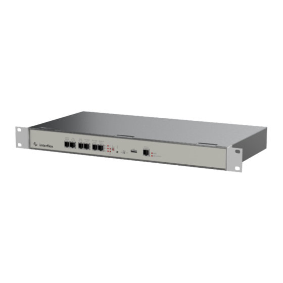
- Page 1 Controller IF-4070 Controller 00-4070-00xx...
-
Page 2: Table Of Contents
Table of contents Table of contents 1 General information.......................... 1.1 Short description ......................... 1.2 Scope of delivery ........................1.3 Intended use ..........................1.4 Target group ..........................1.5 Safety ............................1.6 Abbreviations ..........................1.7 Cable lengths and cable types....................2 System overview..........................2.1 Range of functions ........................ -
Page 3: General Information
General information 1 General information 1.1 Short description The controller IF-4070 serves as the connecting link between a maximum of 16 Interflex readers for time & attendance recording or access control. Eight integrated relays and eight input contacts allow for the control and monitoring of doors, for example. -
Page 4: Safety
General information Only perform the actions described in this document if you belong to this target group. Interflex Datensysteme GmbH is not liable for any damages caused by improper installation or initial operation. 1.5 Safety WARNING Danger to life due to electric shock People can be seriously hurt or killed through physical contact with live parts (e.g. -
Page 5: Cable Lengths And Cable Types
General information Ground IEEE Institute of Electrical and Electronics Engineers NC contact Normally closed contact NO contact Normally open contact Power over Ethernet RFID Radio-Frequency Identification Shield Secure shell 1.7 Cable lengths and cable types Cable Function Max. Length Recommended cable type 230 V AC power supply to power supply unit (if not NYM 3 x 1.5 mm pre-installed) -
Page 6: System Overview
System overview 2 System overview Controller Cable to floating status contacts Inputs for floating status contacts Control cable Relay with 30V, 2A switch contacts Power cable (not applicable for PoE) Switch or PoE device Ethernet without PoE Host system Terminal bus cable Readers for recording time data RS485 branch cable from reader to bus cable Reader for access control... -
Page 7: Range Of Functions
System overview 2.1 Range of functions Main functions of the If-407x controller: Field of Application The controllers are operated with the IF6020 or IF6040 host system and control up to 16 Interflex readers for time & attendance recording or access control that are distributed among three RS485 interfaces. The controllers check the booking data from the readers and transfer it to the host system in real-time. -
Page 8: If-4070 Controller Overview
System overview 2.3 IF-4070 controller overview Connections on the printed circuit board USB connection (for future use) 14-pin screw terminal for floating status contacts 14-pin screw terminal for floating status contacts and relay contacts 14-pin screw terminal for relay contacts 6-pin screw terminal for relay contacts Screw terminal for the connection of the power supply RJ45 socket for the connection to the Ethernet network (host system) - Page 9 System overview LEDs and switches Status Operating mode of the controller Bus 1 / 2 / 3 Lights up Data exchange with reader on bus 1 / 2 / 3 Lights up Application has been started; controller is ready for operation LINK Flashing Network data exchange...
-
Page 10: Mounting The Controller
Mounting the controller 3 Mounting the controller NOTICE Damage to property due to manipulation of the controller Manipulation of the controller can lead to data loss. Install the controller in the secured area, taking the technical requirements into account With the two enclosed housing brackets, you can mount the controller into a 19” cabinet. Housing bracket Angle bracket The illustration shows the installation with housing brackets... -
Page 11: Connecting The Controller
Connecting the controller 4 Connecting the controller 4.1 Removing the housing lid Power cable with Schuko plug Nuts for fastening the housing lid 1. Disconnect device from the power supply. 2. Loosen and remove the nuts and take off the housing cover 4.2 Wiring components The cables can be fixed to the cutouts in the bottom plate of the housing with cable ties. - Page 12 Connecting the controller Bus data cables with readers You can connect up to 8 readers to each bus interface. A maximum of 16 readers can be connected to the controller. Always connect a reader with address 1 to bus 1. Evenly distribute the readers among the three bus interfaces.
- Page 13 Connecting the controller Floating status contacts and relays You can connect the following to screw connectors 800 to 803: Up to 8 floating status contacts, such as e.g. reed contacts. Up to 8 electrical devices that can be switched via relay, such as e.g. electrical door openers or signal lamps up to 30V 2A.
-
Page 14: Connecting The Power Supply
Connecting the controller Screw terminals overview Screw terminals for floating status contacts Input 1 Input 2 Input 3 Input 4 Input 5 Input 6 Input 7 Input 8 11 IN 1 13 IN 2 1 IN 3 3 IN 4 5 IN 5 7 IN 6 9 IN 7... -
Page 15: Initial Operation
Initial operation These measures have been implemented in the distributors from Interflex. For further information, please get in touch with your Interflex contact. Possible power supply for the controller: Integrated (toroidal) transformer 230 V 18 to 24 V AC/DC power supply unit PoE device IEE 802.3at, power class 4 (up to 25.4 W) Set the jumper according to the selected power supply type (see below). -
Page 16: Connecting The Controller To The Network
Initial operation Service interface IF-4xxx controller 75-4070-0001 service cable 4xxx (connection in housing) IF-4070 controller 75-4070-0002 service cable 4xxx (connection via RJ45) IF-5xxx terminal 75-99-0006 Service cable 5xxx 5.1 Connecting the controller to the network You can connect the controller to the network via a service cable and the serial service interface or via WLAN with the IF-ServiceApp. - Page 17 Initial operation 5. Start communication with Open 6. Log in with username fieldservice 7. Specify a password Details on valid password requirements and how to change a password can be found under Users and passwords. Only after entering a password are the network services started and the network connection can be established.
-
Page 18: Checking And Setting Network Parameters
Initial operation 5.2 Checking and setting network parameters The netpar -? command lists the call parameters of the netpar command: fieldservice@IF‑xxx:~ netpar -? Display or change network parameters (legacy) Please consider using nmtui or nmcli instead. Usage: /opt/interflex/bin/netpar [OPTION] -i show network settings ... - Page 19 Initial operation fieldservice@IF‑xxx:~ netpar -x IPv4 address/netmask [172.18.12.65/16]: IPv4 gateway [172.18.70.1]: Port [2001]: Hostname [IF‑xxx]: Connection 'netpar' (e046c1c5-2eb5-4be0-8655-4f79acffc8bc) successfully deleted. Connection 'netpar' (8ff8bd2e-7229-4914-a214-3d60dc0e7f16) successfully added. Activate profile netpar Connection successfully activated (D-Bus active path: /org/freedesktop/NetworkManager/ ActiveConnection/3) Current profile: netpar IPv4 address/netmask: 172.18.12.65/16 IPv4 gateway: 172.18.70.1 IPv4 address/netmask (active): 172.18.12.65/16 IPv4 gateway (active): 172.18.70.1...
-
Page 20: Configuring The Interfaces And The Booking Memory
Initial operation 5.3 Configuring the interfaces and the booking memory Via the command oc -h, you can change interface settings adjust the size of the booking memory Press the Enter key to confirm values that you do not wish to change. fieldservice@IF xxxx:~ oc -h base address : 1 No. -
Page 21: Listing The Configuration Data Of Readers
Initial operation 5.4 Listing the configuration data of readers The cfg command lists the configuration data of readers. fieldservice@IF xxxx:~ cfg Terminal configuration IF xxxx/4735 IT-2018.02.0-794-g91e557d6d26e Host: Ethernet ---------------------------------------------------------------- No B A HA TNo type HWU SWU display keys read.1 read.2 In/Out I/O -- - - -- --------- ------- ----- ----- ------- ------ ------ -- 1 1 A 1 0 IF611 3.00 7.b ../.. -
Page 22: Restarting The Controller
Initial operation 5.5 Restarting the controller Some changes require a restart of the controller. You can do this directly on the controller or with the appropriate commands via the console. Warm boot A warm boot performs the following actions: Close application Restart application Associated console command: oc -s or factory-reset application-restart Reboot... - Page 23 Initial operation Cold boot All settings made on the controller via IF-6040 or OC Task are deleted or reset to default. System or operating system settings, such as the IP address or password, are retained. Use the cold boot during initial operation and in the event of malfunctions that cannot be remedied by other means, e.g., a warm boot.
-
Page 24: Updating The Software
Updating the software Factory reset All factory settings are restored. For initial operation, the controller can then only be accessed via a serial console or the IF- ServiceApp. 1. Set switches: 2. Shortly press the Reset button 3. Wait until the RUN LED lights up again (procedure can take up to 30 seconds) 4. -
Page 25: Upgrading The Controller
Upgrading the controller 7 Upgrading the controller The functional scope of a controller depends on the purchased license. You can extend (upgrade) this license, if necessary. Example: Upgrading an IF-4070 controller with 8 terminals to a controller with 16 terminals After ordering an upgrade, you will receive two files from Interflex: Batch file s_tclicence.bat License file *.xml... -
Page 26: Disposal
Disposal Output relay/switching capacity 8 relays with 'normally closed’ (NC) and 'normally open’ (NO) contacts Switching capacity up to 30 V, 2 A Operating status indicators 7 LEDs on front panel General data Ambient temperature +4°C to +40°C Humidity Max. 95%, non-condensing Degree of protection IP30 Dimensions (H x W x D) - Page 27 The original manual is in German. Other languages are translations of the original manual. Version: 10.21 Interflex Datensysteme GmbH +49 711 1322 - 0 Zettachring 16 interflex.info@allegion.com 70567 Stuttgart, Germany www.interflex.de...
Need help?
Do you have a question about the Interflex IF-4070 and is the answer not in the manual?
Questions and answers