Table of Contents
Advertisement
Quick Links
Advertisement
Table of Contents

Subscribe to Our Youtube Channel
Related Manuals for Allegion Interflex IF-4735


Summary of Contents for Allegion Interflex IF-4735
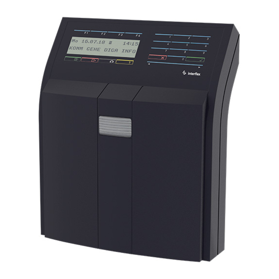
- Page 1 Terminal IF-4735 Time Recording Terminal 00-4735-04xx...
-
Page 2: Table Of Contents
Table of contents General information......................Short description....................... Scope of delivery ...................... Target group ......................Intended use ......................Safety........................Abbreviations ......................Cable lengths and cable types.................. System overview........................Service interface ....................... Mounting the terminal ......................Opening the housing....................Fastening the back panel of the housing ..............Wiring the terminals and the components .............. - Page 3 Disposal ..........................24 Declarations of conformity ....................24 UK Declaration of Conformity ................... 24 EU Declaration of Conformity ................... 24 © 2022 Interflex Datensysteme GmbH | IF-4735 Time Recording Terminal | 04.22...
-
Page 4: General Information
1 General information 1 General information 1.1 Short description The IF-4735 terminal includes the following functions: Contactless identification and data recording Power supply via PoE (Power over Ethernet) or via power supply unit with 18 - 24 V AC/DC or optional with 230 V AC. Connection of up to 7 terminals for access control Connection of up two I/O controller boards for controlling and monitoring doors (optional) -
Page 5: Safety
1 General information Any other use is not in accordance with the intended purpose and therefore not permitted. Modifications to the device are not permitted. 1.5 Safety WARNING Danger to life due to electric shock People can be seriously hurt or killed through physical contact with live parts (e.g. 230 V~). Make sure that you cannot touch live lines during installation. -
Page 6: Cable Lengths And Cable Types
1 General information IEEE Institute of Electrical and Electronics Engineers NC contact Normally closed contact NO contact Normally open contact Power over Ethernet RFID Radio-Frequency Identification Shield Secure shell 1.7 Cable lengths and cable types Cable function Max. length Recommended cable type 230 V AC power supply to power supply unit (if not NYM 3 x 1.5 mm pre-installed) -
Page 7: System Overview
2 System overview 2 System overview The following figure shows a sample configuration with an access control terminal IF-800. Host system Time recording terminal IF-4735 External voltage supply (optional) PoE device: switch or power injector I/O controller board I/O connector board Access control terminal IF-800 2.1 Service interface For the connection between the terminal and the service PC, an RS-232 service cable can be... -
Page 8: Mounting The Terminal
3 Mounting the terminal Settings Parameters Settings for RS232 Baud rate 115200 Parity 8 / none Stop bits Flow control Xon/Xoff 3 Mounting the terminal 3.1 Opening the housing Prerequisites ü The device is switched off the power supply. Procedure 1. -
Page 9: Fastening The Back Panel Of The Housing
3 Mounting the terminal 3.2 Fastening the back panel of the housing Installation site Please observe the following recommendations: Permitted ambient conditions for the device Minimum distance of 10 cm between the connecting cables and the nearest power cable Installation height 1200 mm Minimum distances between RFID and BLE devices If several RFID devices are mounted too close together, mutual interference may occur. - Page 10 3 Mounting the terminal Fasten the back panel using 3 screws as shown in the figure. The following figure shows the back panel of the housing and its side view with a mounted terminal. 3 bore holes for wall mounting Cutout for installed cables (in-wall) Installed cables (flush-mounted) Feeder for cables (surface-mounted)
-
Page 11: Wiring The Terminals And The Components
3 Mounting the terminal 3.3 Wiring the terminals and the components NOTICE Dommages matériels dus à un branchement incorrect de l’appareil Tout branchement incorrect peut endommager l’appareil. Les branchements électriques doivent se faire hors tension. Ne pas modifier les ponts enfichables (cavaliers) et les commutateurs DIP lorsque l’appareil est sous tension. - Page 12 3 Mounting the terminal 2. Plug in the jumper The factory setting is power supply via power supply unit. Redundant power supply To supply the terminals with redundant power, you need an external 18 V DC 1 A power supply unit.
- Page 13 3 Mounting the terminal Optional: Connecting internal I/O controller boards It is possible to connect up to two I/ O controller boards for controlling floating status contacts (relays) via the external reader unit. +/AC -/AC +/AC -/AC COM + COM - Power supply Control element, e.g.
-
Page 14: Closing The Housing
4 Initial operation Optional: Connecting external I/O controller boards Up to 7 access control terminals can be connected to the IF-4735 terminal via an I/O controller board. A description on how to connect these terminals to the I/O connector board can be found in the corresponding technical manual. -
Page 15: Connecting The Controller To The Network
4 Initial operation 4.1 Connecting the controller to the network You can connect the controller to the network via a service cable and the serial service interface or via WLAN with the IF-ServiceApp. IF-ServiceApp Prerequisites ü Controller is connected to the IF-ServiceApp. Detailed information on this subject can be found in the documentation of the IF-ServiceApp. -
Page 16: Checking And Setting Network Parameters
4 Initial operation Boot the operating system Start applications Connect the components The start-up procedure takes up to 30 seconds. When the RUN LED lights up, an SSH connection can be established. Leave PuTTY open during the next steps as further entries are required during initial operation. - Page 17 4 Initial operation Confirm values (e.g. Gateway, Netmask, etc.) that you do not wish to change by pressing the Enter key. When your changes are complete, a list of the current network parameters is displayed after a few seconds and then the connection to the controller is terminated. ...
-
Page 18: Configuring The Interfaces And The Booking Memory
4 Initial operation 4.3 Configuring the interfaces and the booking memory Via the command oc -h, you can change interface settings adjust the size of the booking memory Press the Enter key to confirm values that you do not wish to change. ... -
Page 19: Listing The Configuration Data Of Terminals
4 Initial operation 4.4 Listing the configuration data of terminals The cfg command lists the configuration data of terminals. fieldservice@IF xxxx:~ cfg Terminal configuration IF xxxx/4735 IT-2018.02.0-794-g91e557d6d26e Host: Ethernet ---------------------------------------------------------------- No B A HA TNo type HWU SWU display keys read.1 read.2 In/Out I/O -- - - -- --------- ------- ----- ----- ------- ------ ------ -- 1 1 A 1 0 IF611 3.00 7.b ../.. -
Page 20: Restarting The Controller
4 Initial operation 4.5 Restarting the controller Some changes require a restart of the controller. You can do this directly on the controller or with the appropriate commands via the console. Reset button DIP switches RUN LED Warm boot A warm boot performs the following actions: Close application Restart application Associated console command: oc -s or factory-reset application-restart... - Page 21 4 Initial operation Use the cold boot during initial operation and in the event of malfunctions that cannot be remedied by other means, e.g., a warm boot. 1. Set switches: 2. Shortly press the Reset button 3. Wait until the RUN LED lights up again permanently (procedure can take up to 45 seconds) 4.
-
Page 22: Encryption With Tls (Transport Layer Security)
5 Technical specifications 4. Reset switch position: Associated console command: factory-reset full 4.6 Encryption with TLS (Transport Layer Security) To encrypt the data transmission between the host system and the controller using the TLS protocol, additional adjustments must be made during the setup in the IF-6040 system. Detailed information on this subject can be found in the documentationIF-6040 Administration. -
Page 23: Maintenance And Cleaning
6 Maintenance and Cleaning Inputs Up to two I/O controller boards with 2 floating sensors each (optional) Output relay/switching capacity Up to two I/O controller boards with 1 floating sensors each (optional), max. 30 V / 2 A Anti-tamper switch Optional: Anti-tamper switch, activated when front panel is removed General data... - Page 24 The original manual is in German. Other languages are translations of the original manual. Version: 04.22 Interflex Datensysteme GmbH +49 711 1322 - 0 Epplestraße 225 (Haus 3) interflex.info@allegion.com 70567 Stuttgart, Germany www.interflex.com © 2022 Interflex Datensysteme GmbH | All specifications are subject to change without notice.
Need help?
Do you have a question about the Interflex IF-4735 and is the answer not in the manual?
Questions and answers