Table of Contents
Advertisement
Advertisement
Table of Contents

Related Manuals for Allegion Interflex IF-5735


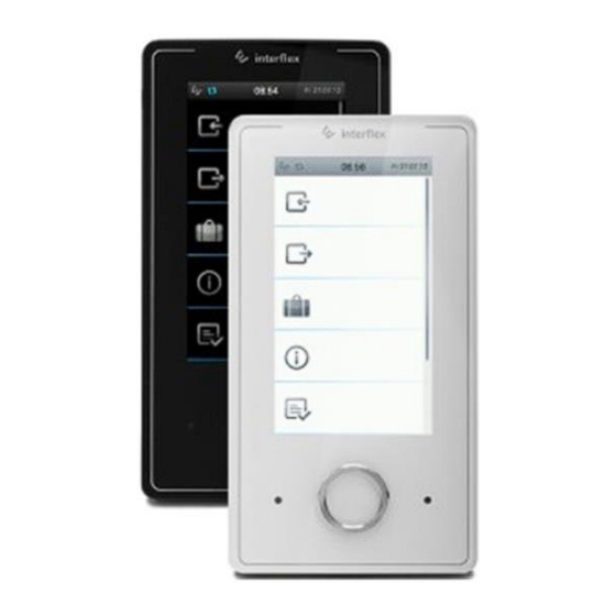
Summary of Contents for Allegion Interflex IF-5735
- Page 3 Copyright © 2017 Version Date: July 26, 2017 Interflex Datensysteme GmbH Allegion Zettachring 16 D-70567 Stuttgart, Germany Phone: +49 (0711) 1322 0 Internet e-mail: interflex.info@allegion.com Website: http://www.interflex.de Interflex operates as part of Allegion plc. For more information on Allegion, please visit www.allegion.com.
-
Page 5: Table Of Contents
Contents Contents General Scope of delivery........................1 Target group ......................... 1 Symbols used in this document ................... 1 Intended use ........................1 General safety instructions ....................2 All specifications are subject to change without notice ............2 List of abbreviations ......................2 System Overview IF-57xx terminal family ...................... - Page 6 Contents Accessories Overview Technical Specifications EU Declaration of Conformity ....................16 Open source program packages..................16 Disposal...
-
Page 7: General
1 General 1.1 Scope of delivery The package contains: Housing with reader electronics and touchscreen PoE terminal board 14-pin ribbon cable Back panel of housing Accessory bag with mortise lock and fasteners Installation instructions Please check the completeness and condition of the shipment upon receipt. -
Page 8: General Safety Instructions
General 1.5 General safety instructions For the safety of you and others, please observe the following safety instructions: Danger to life due to electric shock People can be seriously hurt or killed through physical contact with live parts (e.g. 230 V~). Make sure that you cannot touch live lines during installation. -
Page 9: System Overview
System Overview 2 System Overview Figure: Configuration example using 3 IF-5735 master terminals The IF-57xx master terminal and the PoE terminal board are connected by a 14-pin ribbon cable. The power supply as well as the connection to the data lines takes place via this ribbon cable. To comply with the required EMC values, the IF-57xx requires functional grounding. -
Page 10: Sockets, Leds And Switches
System Overview 2.2 Sockets, LEDs and switches Designation Function Anti-tamper switch Triggers an alarm when the housing is opened. To suppress this alarm, it must be turned off by a parameter setting in the time recording program. USB port WLAN connection phyCore board Device control 2x Ethernet LEDs... -
Page 11: Proximity Sensor
System Overview 2.4 Proximity sensor The terminal is equipped with a proximity sensor. If the terminal is not in use, it switches to (power-saving) sleep mode. When someone approaches the terminal, it wakes up and is immediately available. 2.5 Encryption of data transfer Transmission, credential <->... -
Page 12: Mounting The Device
Mounting the Device After receiving the data, the host system evaluates it and reacts depending on the data received. For booking data, the IF-60x0 system sends back a positive or negative booking response, for example. Depending on the booking response, access is either permitted or denied. The IF-60x0 system can also actuate relays or trigger an alarm if certain events occur. -
Page 13: Connecting The Device
Connecting the Device 4 Connecting the Device 4.1 Risk of electric shock Danger to life due to electric shock People can be seriously hurt or killed through physical contact with live parts (e.g. 230 V~). Make sure that you cannot touch live lines during installation. -
Page 14: Reader Electronics To Poe Terminal Board
Connecting the Device 4.3 Reader electronics to PoE terminal board 3-pin terminal strip for connecting the external power supply RJ45 socket for PoE and Ethernet data cable Ribbon cable with suppression sleeves between reader electronics and PoE terminal board. Back panel of housing Connect the reader electronics to the PoE terminal board using the supplied ribbon cable as shown. -
Page 15: Service Interface
Configuring the Device External power supply Connect an external power supply's functional grounding to PE on the PoE terminal board's 3-pin terminal strip. When using an external power supply, connect the functional grounding to PE on the PoE terminal board. See also Unplugging the RJ45 connector ..................... -
Page 16: Establishing The Telnet Connection And Logging In
Configuring the Device 5.3 Establishing the TELNET connection and logging in Establish a TELNET connection via the factory-set IP address. A login can be performed after connection setup. Login: Access to the console and Linux commands is granted after you login with root and enter the corresponding password. -
Page 17: Setting Interfaces, Booking Memory And Encryption
Configuring the Device 5.6 Setting interfaces, booking memory and encryption With the command oc -h, you can: Change interface settings Encrypt data transmission Adjust the size of the booking memory root@IF-xxxx:~ oc -h base address : No. of term. bus 1 : 6 bus 2 : 4 bus 3 : 6... -
Page 18: Listing Slave Terminals
Configuring the Device 5.8 Listing slave terminals With the cfg command, you can list the configuration data of slave terminals. Terminal configuration IF-xxxx V7.xx -------------------------------------------------------------------- No B A HA TNo type HWU SWU display keys read.1 read.2 In/Out I/O -- - - -- --- ---- --- --- ------- ---- ------ ------ ------ ---- 0 IFx 2.04 6.b OL/2x20 ..NF PSCR/P .. -
Page 19: Preparing To Update Software
Configuring the Device 5.10 Preparing to update software You require the PuTTY program package for execution. This is a free, open-source SSH, Telnet and Rlogin client that facilitates remote operation of Unix systems by Windows computers. Install the PuTTY program package (entire package, version >= 0.62). Updates or upgrades are performed using batch files, in which C:\Programs\PuTTY is specified as default installation path for PuTTY. -
Page 20: Performing Device License Upgrade
Maintenance and Service File name Command tctermfwup.bat tctermfwup.bat <terminal firmware file> <IP address controller> The terminal number is hard-coded in the batch file, e.g.: sh% -pw %ctrl_password% root@%2 "%dest_bin_dir%/etp 1 -fun %1 Updates to multiple controllers are performed individually for each one. To do so, open the batch file in an editor and change the number of the controller. -
Page 21: Accessories Overview
Accessories Overview 7 Accessories Overview The following items are available as accessories: Order Number Item 41-10015 Transformer for external power supply 230/19 V AC, 0.8 A 41-10106 Transformer with DIN rail mounting for external power supply 75-99-0006 USB-to-serial adapter for service purposes 75-700-0141 I/O controller board with 1 relay and 2 digital inputs Spacer... -
Page 22: Eu Declaration Of Conformity
The owner can dispose of the device himself or return it to the supplier. Copyright © 2017 Version Date: July 26, 2017 Interflex Datensysteme GmbH Zettachring 16, D-70567 Stuttgart, Germany Tel.: +49 (0711) 1322 0 Internet E-Mail: interflex.info@allegion.com Websites: www.interflex.de www.allegion.com...
Need help?
Do you have a question about the Interflex IF-5735 and is the answer not in the manual?
Questions and answers