Agilent Technologies 1200 Infinity Series Manual
Universal interface box
Hide thumbs
Also See for 1200 Infinity Series:
- User manual (54 pages) ,
- User manual (276 pages) ,
- User manual (244 pages)
Table of Contents
Advertisement
Quick Links
Advertisement
Table of Contents

Related Manuals for Agilent Technologies 1200 Infinity Series


Summary of Contents for Agilent Technologies 1200 Infinity Series
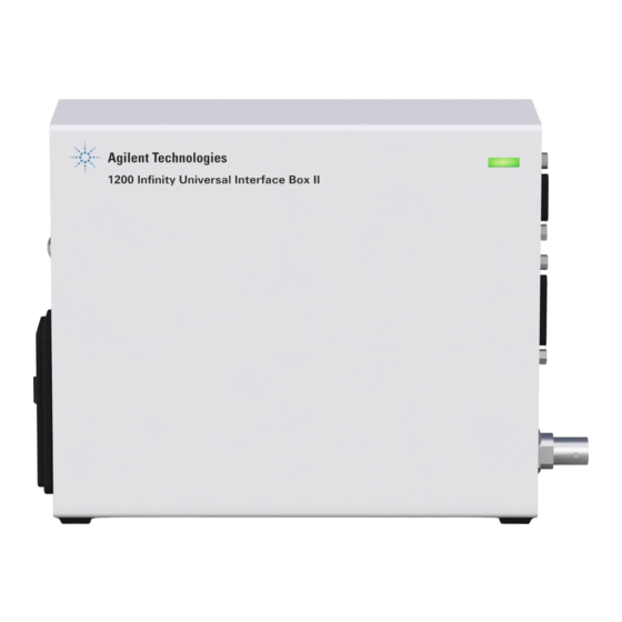
- Page 1 Agilent 1200 Infinity Series Universal Interface Box Agilent Technologies...
- Page 2 Agilent MS rely on the Universal Interface Box II. The Agilent 1200 Infinity Series Universal Interface Box (shortly referred to as UIB II) replaces the Agilent 1100 Series Universal Interface Box (G1390A) which is designed for peak-based fraction collection with external 3rd party detectors via analog signal input or mass-based fraction collection with an Agilent MS via digital signal trigger.
- Page 3 • Low voltage output of 5 V and/or 24 V • Four timetable programmable relay contacts for control of external devices through close/open commands • External leak sensor with separate input line for improved lab safety • CAN connection to 1200 Series LC or 1200 Infinity Series LC modules...
- Page 4 Deployment The following sections describe some of the options for connecting a 1200 Infinity Series LC instrument with other modules or devices. Additional Analog Out for every Agilent module to provide instrument or chromatography signals to 3rd party receivers Figure 2 Connection to provide additional analog out Use any of the following cable options depending on input device: N O T E...
- Page 5 3rd party detector signal acquisition Figure 3 Connection to 3rd party device Use any of the following cable options depending on output device: N O T E #063, #064. For explanations of the option numbers refer to Table 2 on page 14.
- Page 6 3rd party (Peak Detection) triggered fraction collection Figure 4 Connection to 3rd party device for fraction triggering Use any of the following cable options depending on output device: N O T E #063, #064. For explanations of the option numbers refer to Table 2 on page 14.
- Page 7 Mass-Based fraction collection Figure 5 Connection for mass-based fraction collection Use following cable option for 61xx MS systems: #066. N O T E For explanations of the option numbers refer to Table 2 on page 14.
- Page 8 External Contacts Board for time table programmable relay switching allows control of peripheral equipment Figure 6 Connection to use external boards/relay switching functionality Use following cable option: #065. N O T E For explanations of the option numbers refer to Table 2 on page 14.
- Page 9 Connectors of the UIB II Overview of Connectors Figure 7 Right side of the UIB II Figure 8 Left side of the UIB II...
- Page 10 Typical Connection of UIB II to an Agilent LC Stack Figure 9 Connection UIB II to an Agilent LC stack (example) Config Switch Settings of the UIB II Figure 10 Config Switch Figure 11 Dipswitch 1 and 2 Table 1 Config Switch Settings Dipswitch 1 Dipswitch 2...
-
Page 11: Special Settings
Special Settings Boot-Resident Firmware update procedures may require this mode in case of firmware loading errors (main firmware part). If you use the following switch settings and power the instrument up again, the instrument firmware stays in the resident mode. It is not operable as a module. It only uses basic functions of the operating system for example, for communication. - Page 12 ERI / GPIO Figure 14 ERI / GPIO Enh. Remote IO 1 IO 2 IO 3 IO 4 IO 5 IO 6 IO 7 IO 8 1wire DATA DGND +5 V ERI out PGND PGND +24 V ERI out +24 V ERI out ERI Interface (Enhanced Remote Interface) Description: This interface contains 8 individual programmable input/output pins.
- Page 13 Relay / Aux. Figure 15 Relay / Aux. Function AUX 1 A-GND AUX 2 A-GND D-GND...
- Page 14 Cables for UIB II Cable Overview UIB II Table 2 UIB II Cable Overview Option Cable part Description Usage number number #061 8120-8140 For Analog Out to BNC BNC to BNC #062 01046-60105 For Analog Out BNC to general purpose #063 35900-60910 For Analog...
- Page 15 Table 2 UIB II Cable Overview Option Cable part Description Usage number number #065 G1103-61611 For External Contacts External contacts to general purpose #066 G1968-60805 Mass-based Fraction Collection ERI to MS RJ-45 #067 5188-8029 General Purpose (GPIO/ERI) ERI to general purpose...
-
Page 16: Analog Cables
Analog Cables p/n 8120-1840 Contact/Lead Signal Name Shield Analog - Center Analog + p/n G1390-60002 Contact Lead Signal Name Analog - Analog + Shield Analog - Center Analog + p/n 01046-60105 Contact/Lead Signal Name Black Analog - Analog + Shield Analog - Center Analog +... - Page 17 p/n G35900-60910 Contact/Lead Signal Name Analog - Analog + Black Analog - Analog +...
-
Page 18: External Contact Cable
External Contact Cable One end of this cable provides a 15-pin plug to be connected to Agilent modules interface board. The other end is for general purpose. Agilent Module Interface Board to general purposes p/n G1103-61611 Color Signal Name Agilent module White EXT 1... - Page 19 General Purpose Cable Table 3 GPIO General Purpose Cable (5188-8029) descriptions Wire Color Enh. Remote Green IO 1 Violet IO 2 Blue IO 3 Yellow IO 4 Black IO 5 Orange IO 6 IO 7 Brown IO 8 Gray 1 wire DATA DGND +5 V ERI out PGND...
- Page 20 Representation in the Driver Software The representation of the UIB II in the dashboard of the Rapid Control LC Driver provides information on the following items: • Connectors Analog In • Analog Out • • Relay contacts • Voltage out information (if used) Figure 16 Dashboard tile of the G1390B driver Table 4...
-
Page 21: Electrical Connections
Appendix Electrical Connections • The CAN bus is a serial bus with high speed data transfer. The two connectors for the CAN bus are used for internal module data transfer and synchronization. • The power input socket accepts a line voltage of 100 – 240 VAC ±10 % with a line frequency of 50 or 60 Hz. -
Page 22: Physical Specifications
Physical Specifications Table 5 Physical Specifications Type Specification Comments Weight 0.9 kg (2 lbs) Dimensions 165 x 135 x 55 mm (6.5 x 5.3 x 2.2 inches) (height × width × depth) Line voltage 100 – 240 VAC, ± 10 % Wide-ranging capability Line frequency 50 or 60 Hz, ±... - Page 23 Technical and Performance Specifications Table 6 Performance specifications Type Comment High breaking capacity fuse 2.0 A, 250 V Signal specifications: 2-wire serial bus system Analog-input Input Range= -1 V to 1 V Resolution = 24 bit A/D-Converter Effective System Resolution = +/- 1 uV (rms) GPIO TTL compatible Input and Output Open collector characteristic Input voltage range 0 V to 5 V...
-
Page 24: Delivery Checklist
Power cord Damaged Packaging If the delivery packaging shows signs of external damage, please call your Agilent Technologies sales and service office immediately. Inform your service representative that the instrument may have been damaged during shipment. "Defective on arrival" problems... -
Page 25: Bench Space
Condensation Condensation within the module C A U T I O N Condensation will damage the system electronics. ➔ Do not store, ship or use your module under conditions where temperature fluctuations could cause condensation within the module. ➔ If your module was shipped in cold weather, leave it in its box and allow it to warm slowly to room temperature to avoid condensation. -
Page 26: Power Cords
Never operate your instrumentation from a power outlet that has no ground connection. ➔ Never use a power cord other than the Agilent Technologies power cord designed for your region. Use of unsupplied cables WA R N I N G Using cables not supplied by Agilent Technologies can lead to damage of the electronic components or personal injury. -
Page 27: Power Considerations
Power Considerations The module power supply has wide ranging capability. It accepts any line voltage in the range described in Table 5 on page 22. Consequently there is no voltage selector at the left side of the module. There are also no externally accessible fuses, because automatic electronic fuses are implemented in the power supply. - Page 28 The Waste Electrical and Electronic Equipment Directive Abstract The Waste Electrical and Electronic Equipment (WEEE) Directive (2002/96/EC), adopted by EU Commission on 13 February 2003, is introducing producer responsibility on all electric and electronic appliances starting with 13 August 2005. This product complies with the WEEE Directive (2002/96/EC) N O T E marking requirements.
-
Page 29: Safety Symbols
Safety Symbols Table 7 Safety Symbols Symbol Description The apparatus is marked with this symbol when the user should refer to the instruction manual in order to protect risk of harm to the operator and to protect the apparatus against damage. Indicates dangerous voltages. -
Page 30: Operation
Operation Before applying power, comply with the installation section. Additionally the following must be observed. Do not remove instrument covers when operating. Before the instrument is switched on, all protective earth terminals, extension cords, auto-transformers, and devices connected to it must be connected to a protective earth via a ground socket. -
Page 31: Safety Standards
The operator of this instrument is advised to use the equipment in a manner as specified in this manual. Agilent Technologies on Internet For the latest information on products and services visit our worldwide web site on the Internet at:... - Page 32 © *G1390-90011* Part Number: Agilent Technologies, Inc 2012, G1390-90011 2013 *G1390-90011* G1390-90011 Edition: 02/2013 Agilent Technologies, Inc Printed in Germany Hewlett-Packard-Strasse 8 76337 Waldbronn, Germany...