Table of Contents
Advertisement
Advertisement
Table of Contents

Related Manuals for Agilent Technologies Agilent G1369B


Summary of Contents for Agilent Technologies Agilent G1369B
-
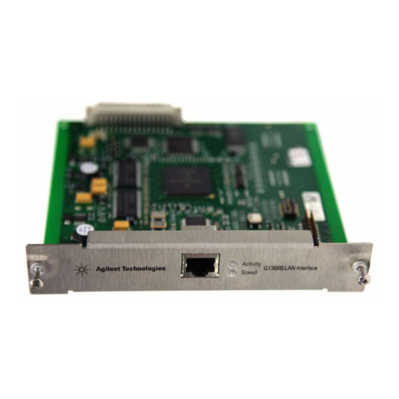
Page 1: Lan Interface
Agilent G1369B LAN Interface User Manual Agilent Technologies... -
Page 2: G1369B Lan Interface User Manual
Software Revision Technology Licenses This guide is valid for A.01.xx revisions of the Agilent G1369B LAN Interface software, The hardware and/or software described in WA R N I N G where xx refers to minor revisions of the... - Page 3 In This Guide… This guide contains information to install the LAN Interface (G1369B). Introduction - Around your LAN Interface In this chapter you will find an introduction to the LAN Interface and its function. Getting Started In this chapter you will find instructions to help you to set-up your LAN Interface based on the Agilent 1100/1200/1260 series HPLC modules.
- Page 4 G1369B LAN Interface User Manual...
-
Page 5: Table Of Contents
Contents Introduction to the LAN Interface Versions of LAN Cards LAN Control - What Exactly Does It Do? LAN Interface - What Has To Be Done? LAN Control Configurations LAN Interface Compatibility Installing and Cabling the LAN Interface What You Will Get What You Have To Do First LAN Interface Configuration TCP/IP Parameter Configuration... - Page 6 Contents Update Procedure Agilent Support Information Reporting of Problems Agilent Web Glossary G1369B LAN Interface User Manual...
- Page 7 Agilent G1369B LAN Interface User Manual Introduction - Around your LAN Interface Introduction to the LAN Interface LAN Control - What Exactly Does It Do? LAN Interface - What Has To Be Done? LAN Control Configurations Local Configuration Using Cross-over Cable...
-
Page 8: Introduction To The Lan Interface
Introduction - Around your LAN Interface Introduction to the LAN Interface Introduction to the LAN Interface The LAN Interface (Local Area Network) is the Agilent replacement for the previously used HP JetDirect card in the Agilent 1100/1200/1260 series HPLC modules, the 8453 UV-vis spectrophometer, the 35900E A/D converter and the 6850 Series GC. -
Page 9: Versions Of Lan Cards
Introduction - Around your LAN Interface Introduction to the LAN Interface Versions of LAN Cards Table 1 Product Number Part Number Comments • G1369B G1369-60002 introduced 03/2010, same features as G1369A, replaces G1369A, backward compatible • G1369A G1369-60001 introduced 10/2003 Compared to the G1369A LAN Card, SW 7 and SW 8 must be always in OFF position on the G1369B N O T E LAN Card, otherwise the selected modes are not working. -
Page 10: Lan Interface - What Has To Be Done
Introduction - Around your LAN Interface Introduction to the LAN Interface LAN Interface - What Has To Be Done? • install LAN Interface into the instrument • install network interface card (NIC) into PC (if not already pre-installed or on-board). •... -
Page 11: Lan Control Configurations
Introduction - Around your LAN Interface Introduction to the LAN Interface LAN Control Configurations The basic LAN configurations are shown below. Local Configuration Using Cross-over Cable The simplest way is a configuration with a single system. Patch-cable Cross-over Shielded 3 m (5023-0203) Figure 2 Local configuration using cross-over cable LAN Using a HUB and Twisted Pair Cables... -
Page 12: Lan With Existing Customer Network
Introduction - Around your LAN Interface Introduction to the LAN Interface LAN With Existing Customer Network Use MDI/MDI-X port or “Cascade” Port with standard twisted pair cable to connect Hub to a “parent” hub. IP Addresses and other TCP/IP configuration information MUST be provided by the customer’s IT organization. -
Page 13: Lan Interface Compatibility
Introduction - Around your LAN Interface Introduction to the LAN Interface LAN Interface Compatibility The table below lists the minimum requirements for LAN operation with the LAN Interface. Table 2 LAN Compatibility Instrument/Operating Software Revision (minimum) Agilent 1100/1200 modules Firmware A.03.80 and Revision 2 mainboard, see Table 3 Agilent 1260 Infinity modules All revisions... - Page 14 Introduction - Around your LAN Interface Introduction to the LAN Interface LAN Compatibility On Early 1100 Modules All 1100 Series HPLC modules shipped prior to 1997 are NOT compatible with the LAN Interface communication. The modules which host the LAN Interface (usually the detector module) requires a new main board.
- Page 15 Agilent G1369B LAN Interface User Manual Getting Started Installing and Cabling the LAN Interface What You Will Get What You Have To Do First LAN Interface Configuration TCP/IP Parameter Configuration Configuration Switches Initialization Mode Selection Using Stored Using Default Bootp Bootp &...
-
Page 16: Installing And Cabling The Lan Interface
Getting Started Installing and Cabling the LAN Interface Installing and Cabling the LAN Interface What You Will Get • G1369B LAN Interface • LAN cables (for part numbers see “Repair and Parts Information” page 54) Patch-cable Patch-cable Twisted pair Shielded 7 m Cross-over Shielded 3 m (5023-0202) (5023-0203) -
Page 17: What You Have To Do First
Getting Started Installing and Cabling the LAN Interface What You Have To Do First Use an ESD (Electro-Static Discharge) wrist strap when handling electronics. Refer to your N O T E instrument manual for details. 1 Remove the LAN Interface from it’s packaging. Configuration switch, “Configuration Switches”... - Page 18 Getting Started Installing and Cabling the LAN Interface 2 Note the MAC (Media Access Control) address for further reference. The MAC or hardware address of the LAN Interface is a world wide unique identifier. No other network device will have the same hardware address. The MAC address can be found on a label on the card (see Figure 6 page 17).
- Page 19 Getting Started Installing and Cabling the LAN Interface In 1100/1200/1260 systems, the LAN Interface should be installed in the detector (DAD, N O T E MWD, FLD, VWD) due to its higher data handling rate. If no 1100/1200/1260 detector available, use the pump or the autosampler (in this order). The LAN Interface is shipped with the Bootp initialization mode and will use the N O T E parameters (IP, Subnet Mask and Default Gateway addresses) from a Bootp server.
-
Page 20: Lan Interface Configuration
Getting Started LAN Interface Configuration LAN Interface Configuration TCP/IP Parameter Configuration To operate properly in a network environment, the LAN Interface must be configured with valid TCP/IP network parameters. These parameters are: • IP address • Subnet Mask • Default Gateway The TCP/IP parameters can be configured by the following methods: •... -
Page 21: Configuration Switches
Getting Started LAN Interface Configuration Configuration Switches The configuration switches are mounted on the card, see Figure Figure 10 Location of Configuration Switches The LAN Interface is shipped with all switches set to OFF, as shown above. Table 4 Factory Default Settings Initialization (‘Init’) Mode Bootp, for details see page 22... -
Page 22: Initialization Mode Selection
Getting Started LAN Interface Configuration Initialization Mode Selection The following initialization (init) modes are selectable: Table 5 Initialization Mode Switches SW 4 SW 5 SW 6 SW 7 SW 8 Init Mode Bootp Bootp & Store Using Stored Using Default Compared to the G169A LAN Card, SW 7 and SW 8 must be always in OFF position on the G1369B N O T E LAN Card, otherwise the selected modes are not working. -
Page 23: Bootp & Store
Getting Started LAN Interface Configuration Bootp & Store When “Bootp & Store” is selected, the parameters obtained from a Bootp Server become the active parameters immediately. In addition, they are stored to the non-volatile memory of the card. Thus, after a power cycle they are still available. -
Page 24: Using Stored
Getting Started LAN Interface Configuration Using Stored When initialization mode “Using Stored” is selected, the parameters are taken from the non-volatile memory of the card. The TCP/IP connection will be established using these parameters. The parameters were configured previously by one of the described methods. Non-Volatile Active Parameter... - Page 25 Getting Started LAN Interface Configuration Since the default IP address is a so-called local address, it will not be routed by any network device. Thus, the PC and the card must reside in the same subnet. The user may open a Telnet session using the default IP address and change the parameters stored in the non-volatile memory of the card.
-
Page 26: Link Configuration Selection
Getting Started LAN Interface Configuration Link Configuration Selection The LAN Interface supports 10 or 100 Mbps operation in full- or half-duplex modes. In most cases, full-duplex is supported when the connecting network device - such as a network switch or hub - supports IEEE 802.3u auto-negotiation specifications. -
Page 27: Automatic Configuration With Bootp
Getting Started Automatic Configuration with Bootp Automatic Configuration with Bootp When automatic configuration with Bootp is selected and the LAN Interface is powered on, it broadcasts a BOOTP (Bootstrap Protocol) request that contains its MAC (hardware) address. A BOOTP server daemon searches its database for a matching MAC address, and if successful, sends the corresponding configuration parameters to the card as a BOOTP reply. - Page 28 Getting Started Automatic Configuration with Bootp 1 The Agilent Bootp Service is placed in the start-up group and automatically is started during the boot process of the PC. 2 Open the Bootp Settings window (Figure 15) and enter the default settings for your setup.
- Page 29 Getting Started Automatic Configuration with Bootp 4 Select Add to enter the enter the module specific information, see Figure • MAC address (from label on the instrument) • host name • IP address • comment (instrument name / location) • subnet mask (if different) •...
- Page 30 Getting Started Automatic Configuration with Bootp 5 Press OK. The parameter are added to the Bootp Manager, see Figure 17 and added to the TabFile, see Figure 15 on page 28: Figure 18 Bootp Manager - check your entries 6 Press Exit Manager and OK to exit the Agilent Bootp Service. 7 Now turn on the module with the detector, wait about 30-60 seconds and view the LogFile, see Figure...
-
Page 31: Configuring The Cag Bootp Server Program
Getting Started Automatic Configuration with Bootp When using this Bootp mode, the parameters are not written into the non-volatile memory N O T E of the detector. If you delete this Bootp Configuration, the Bootp Manager will show up as shown in Figure 16 on page 28 (Bootp mode). - Page 32 Getting Started Automatic Configuration with Bootp Figure 19 Bootp Server 4 Identify your LAN Interface by the MAC address, see Figure If you are working in a network system, you may see other LAN Interfaces appear, N O T E overwriting your LAN Interface information periodically.
- Page 33 Getting Started Automatic Configuration with Bootp 6 Specify the Host Name (LC1100-01), the IP address (134.40.24.230), the Comment (LC1100-01) and the Subnet Mask 255.255.248.0 and the Gateway (134.40.24.1). If you are working in a network system, you need your own addresses. Contact your local IT N O T E group.
- Page 34 Getting Started Automatic Configuration with Bootp Figure 22 Bootp Manager 9 Press Apply to activate the changes. 10 Press OK to exit the Bootp Manager and power cycle the instrument with the LAN Interface, to force it to send a new bootp request again. This time, the MAC address will be recognized by the Bootp Server (Figure 23).
- Page 35 Getting Started Automatic Configuration with Bootp When using this Bootp mode, the parameters are not written into the non-volatile memory N O T E of the card. If you delete this Bootp Configuration, the LAN Interface will show up as shown Figure 19 on page 32 (Bootp mode).
-
Page 36: Storing The Settings Permanently With Bootp Program
Getting Started Storing the Settings Permanently with Bootp Program Storing the Settings Permanently with Bootp Program If you want to change parameters of the card using the Bootp follow the instructions below. Use an ESD (Electro-Static Discharge) wrist strap when handling electronics. Refer to your N O T E instrument manual for details. -
Page 37: Manual Configuration
Getting Started Manual Configuration Manual Configuration Manual configuration only alters the set of parameters stored in the non-volatile memory of the card. It never affects the currently active parameters. Therefore, manual configuration can be done at any time. A power cycle is mandatory to make the stored parameters become the active parameters, given that the initialization mode selection switches are allowing TELNET Session... -
Page 38: With Telnet
Getting Started Manual Configuration With Telnet Whenever a TCP/IP connection to the card is possible (TCP/IP parameters set by any method), the parameters may be altered by opening a Telnet session. 1 Open the system (DOS) prompt window by clicking on Windows START button and select “Run...”. - Page 39 Getting Started Manual Configuration then press [Enter], where parameter refers to the configuration parameter you are defining, and value refers to the definitions you are assigning to that parameter. Each parameter entry is followed by a carriage return. Table 8 Telnet Commands Value Description...
- Page 40 Getting Started Manual Configuration 4 Use the “/” and press Enter to list the current settings. information about the card Product id, firmware revision (A.xx.xx are released versions), MAC address, initialization mode Initialization mode is Bootp The connected PC/Bootserver is 134.40.24.184 active TCP/IP settings stored TCP/IP settings in non-volatile memory (not visible if equal to active TCP/IP settings)
- Page 41 Getting Started Manual Configuration Figure 28 Telnet - Change IP settings 6 When you have finished typing the configuration parameters, type: quit and press [Enter] to store the configuration parameters exit and press [Enter] to exit without storing parameters. If the Initialization Mode Switch is changed now to “Using Stored” mode, the instrument will take the stored settings when the module is re-booted.
-
Page 42: With Agilent Instant Pilot
Getting Started Manual Configuration With Agilent Instant Pilot To configure the TCP/IP parameters before connecting the detector to the network, the Instant Pilot (G4208A) can be used. 1 From the Welcome screen press the More button. 2 Select Configure. 3 Press the DAD (MWD) button. 4 Scroll down to the LAN settings. -
Page 43: With Handheld Controller G1323B
Getting Started Manual Configuration With Handheld Controller G1323B To configure the TCP/IP parameters before connecting the card to the network, the Handheld Controller (G1323B with firmware B.02.02 or above for 1100/1200 series modules only, see “LAN Interface Compatibility” page 13) can be used. 1 Press F5 “Views”, select “System”... - Page 44 Getting Started Manual Configuration 4 A Warning message shall pop up. Press “Continue” (Figure 32). Figure 32 Warning message 5 After the Handheld Controller was reading out the LAN Interface you will get an overview of all the parameters that are set in the card (LAN Interface Status Page).
- Page 45 Getting Started Manual Configuration Agilent Technologies G1369B FW Revision : A.01.01 MAC Address : 0030d3060122 -------------------------------- Init Mode : Bootp Bootp Server : 134.40.30.184 -------------------------------- TCP/IP Properties - active - IP Address : 134.40.24.230 Subnet Mask : 255.255.248.0 Def. Gateway : 134.40.24.1...
- Page 46 Getting Started Manual Configuration Figure 36 TCP/IP parameters 7 Move to the parameter you want to change, enter the new value and press “Enter”. Figure 37 Service G1369B LAN Interface User Manual...
- Page 47 Getting Started Manual Configuration 8 If you completed your changes, press “Done” to leave the Service section. 9 Press F6 “Done” and restart the module by pressing “OK” . Figure 38 Re-boot screen G1369B LAN Interface User Manual...
-
Page 48: Pc And Agilent Chemstation Setup
Getting Started PC and Agilent ChemStation Setup PC and Agilent ChemStation Setup PC Setup for Local Configuration This procedure describes the change of the TCP/IP settings on your PC to match the LAN Interface default parameters in a local configuration (see also “Local Configuration Using Cross-over Cable”... -
Page 49: Agilent Chemstation Setup
Getting Started PC and Agilent ChemStation Setup Agilent ChemStation Setup 1 Start the Configuration Editor of the Agilent ChemStation. Figure 40 Changing the TCP/IP settings of the Agilent ChemStation 2 Add a TCP/IP connection to communicate with the LAN Interface. Use the IP address of the LAN Interface. - Page 50 Getting Started PC and Agilent ChemStation Setup G1369B LAN Interface User Manual...
- Page 51 Agilent G1369B LAN Interface User Manual Getting Help Troubleshooting Link Status LEDs Error Messages Repair and Parts Information Firmware Update Agilent Support Information Reporting of Problems Agilent Web Glossary In this chapter you will find support information about troubleshooting, repair and the Agilent web.
-
Page 52: Troubleshooting
Getting Help Troubleshooting Troubleshooting If the LAN Interface does not successfully connect to the network, there are several ways to get status information from the card. Link Status LEDs On the card, near the RJ-45 connector, two status LEDs are mounted. See Figure Figure 41 Status LEDs... -
Page 53: Error Messages
Troubleshooting Error Messages The error messages are shown in the LAN Interface Status Page on the Control Module (G1323A/B) only, refer to “With Handheld Controller G1323B” page 43. Agilent Technologies G1369B FW Revision : A.01.01 MAC Address : 0030d3060122 --------------------------------... -
Page 54: Repair And Parts Information
Getting Help Repair and Parts Information Repair and Parts Information The repair level of the product Agilent G1369B LAN Interface is replacement of the complete board. Patch-cable Patch-cable Twisted pair Shielded 7 m Cross-over Shielded 3 m (5023-0202) (5023-0203) CD-ROM with the... -
Page 55: Firmware Update
Getting Help Firmware Update Firmware Update The LAN Interface’s firmware can be updated, using the firmware provided by the Agilent support web side. A procedure will be provided with the firmware. The G1369B LAN card does not take the firmware of the G1316A LAN card and vice versa. -
Page 56: Agilent Support Information
40 or Figure 42 on page 53). Agilent Web Latest documentation or firmware updates for this product (Agilent G1369B LAN Interface) can be obtained from the Agilent web side http://www.agilent.com > Life Sciences/Chemical Analysis For firmware select “Technical Support”, then look for “Firmware for LC &... -
Page 57: Glossary
Getting Help Glossary Glossary Table 13 Glossary Term / Acronym Definition 10/100Base-TX Twisted pair Ethernet cable. Bootp Bootstrap Protocol, an Internet protocol that enables a diskless workstation to discover its own IP address Controller Area Network; a shared broadcast bus, which runs at speeds up to 1Mbit/sec;... - Page 58 Getting Help Glossary Table 13 Glossary Term / Acronym Definition Light Emitting Diode MAC address Media Access Control address, a hardware address that uniquely identifies each node of a network. Modular Input/Output; interface specification from Hewlett-Packard RJ-45 connector Registered Jack-45, an eight-wire connector used commonly to connect computers onto a local-area networks (LAN), especially Ethernets.
- Page 60 In This Book This guide contains information to install the LAN Interface (G1369B). • Introduction - Around your LAN Interface • Getting Started • Getting Help © Agilent Technologies, Deutschland GmbH 2010 Printed in Germany 05/10 *G1369-90001* *G1369-90001* G1369-90001 Agilent Technologies...
- Page 61 © Agilent Technologies, Deutschland GmbH 2010 Printed in Germany 05/10 *G1369-90001* *G1369-90001* G1369-90001 Agilent Technologies...
- Page 62 © Agilent Technologies, Deutschland GmbH 2010 Printed in Germany 05/10 *G1369-90001* *G1369-90001* G1369-90001 Agilent Technologies...