Table of Contents
Advertisement
Quick Links
Advertisement
Table of Contents

Related Manuals for Supermicro A+ AS -2114GT-DNR


Summary of Contents for Supermicro A+ AS -2114GT-DNR
- Page 1 A+ Server AS -2114GT-DNR USER’S MANUAL Revision 1.0...
- Page 2 State of California, USA. The State of California, County of Santa Clara shall be the exclusive venue for the resolution of any such disputes. Supermicro's total liability for all claims will not exceed the price paid for the hardware product.
- Page 3 If you have any questions, please contact our support team at: support@supermicro.com This manual may be periodically updated without notice. Please check the Supermicro website for possible updates to the manual revision level. Secure Data Deletion A secure data deletion tool designed to fully erase all data from storage devices can be found on our website: https://www.supermicro.com/about/policies/disclaimer.cfm?url=/wdl/utility/...
-
Page 4: Table Of Contents
Contents Contents Contacting Supermicro ........................7 Chapter 1 Introduction 1.1 Overview ..........................8 1.2 Unpacking the System ......................8 1.3 System Features ........................9 1.4 Chassis Features .......................10 Control Panel ........................10 System: Front View ......................11 System: Rear View ......................12 1.5 Motherboard Layout ......................13 Quick Reference Table ......................15 Chipset Block Diagram......................16... - Page 5 Contents Precautions ........................26 Unpacking .........................26 3.4 Processor and Heatsink Installation ...................27 3.5 Memory ..........................34 Memory Support ......................34 Memory Installation ......................34 DIMM Module Population ....................36 DIMM Installation ......................37 DIMM Removal .........................37 Motherboard Battery ......................38 3.6 Chassis Components ......................39 Storage Drives ........................39 Drive Carrier Indicators ....................39 Removing/Installing Drives ....................40 Installing Expansion Cards....................42...
- Page 6 Contents 5.4 IPMI ............................68 BMC ADMIN User Password ....................68 Chapter 6 UEFI BIOS 6.1 Introduction .........................69 Starting the Setup Utility ....................69 6.2 Main Setup .........................70 6.3 Advanced ..........................72 6.4 IPMI ............................90 6.5 Event Logs .........................93 6.6 Security ..........................95 6.7 Boot ............................99 6.8 Save &...
-
Page 7: Contacting Supermicro
Super Micro Computer, Inc. 980 Rock Ave. San Jose, CA 95131 U.S.A. Tel: +1 (408) 503-8000 Fax: +1 (408) 503-8008 Email: marketing@supermicro.com (General Information) support@supermicro.com (Technical Support) Website: www.supermicro.com Europe Address: Super Micro Computer B.V. Het Sterrenbeeld 28, 5215 ML... -
Page 8: Overview
(with min, one CPU, two DIMMs, one GPU installed). Add on Cards (AOCs) are recommended to be installed by Supermicro due to optimized density of the 2U form factor. Service: OSNBD3 is highly recommended. In addition to the motherboard and chassis, several important parts that are included with the system are listed below. -
Page 9: System Features
Chapter 1: Introduction 1.3 System Features The following table is an overview of the main features of the AS -2114GT-DNR server. System Features Motherboard (per node) H12SSG-AN6 Chassis CSE-227GTS-R2K63P Single AMD EPYC™ 7002/7003 Series Processors in SP3 sockets Note: 7003 series processor drop-in support requires BIOS version 2.0 or newer. Management Chipset ASPEED A2600 BMC/IPMI management controller with enhanced security Memory (per node) -
Page 10: Chassis Features
A+ Server AS -2114GT-DNR User's Manual 1.4 Chassis Features Control Panel Power switches and status LEDs are located on the control panel on the front of the chassis. Figure 1-1. Control Panel (per node) Control Panel Features (per node) Item Feature Description The main power switch applies or removes primary power from the power supply... -
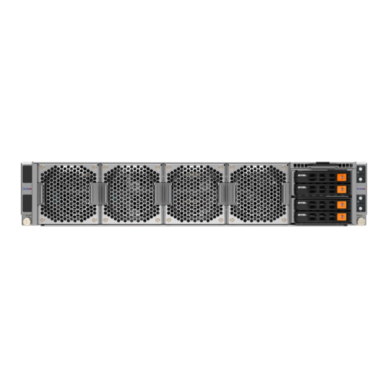
Page 11: System: Front View
Chapter 1: Introduction System: Front View The illustration below shows the features included on the front of the chassis. Externally accessible hard drive carriers display status lights. Control Panel System Cooling Fans Pull-out Tag (Node B) Control Panel (Node A) Figure 1-2. -
Page 12: System: Rear View
A+ Server AS -2114GT-DNR User's Manual System: Rear View The illustration below shows the features on the rear of the chassis. Node B Node A BMC LAN Port Power Supplies VGA Port COM Port Figure 1-4 System Rear View Rear System Features Item Feature Description... -
Page 13: Motherboard Layout
Chapter 1: Introduction 1.5 Motherboard Layout Following is a layout of the H12SSG-AN6 with jumper, connector and LED locations shown. See the table on the following page for descriptions. For detailed descriptions, pinout information and jumper settings, refer to Chapter... - Page 14 A+ Server AS -2114GT-DNR User's Manual USB0/1 COM1 IPMI LAN JWD1 PCB EDGE PCB EDGE JBMC_UART3 JBMC_DEBUG JCOM1 USB0/1 (3.0) JTPM2 JIPMB1 JIPMB1 JBT1 JBT1 CMOS CLEAR LEDM1 JDBG4 LED2 LED2 JCPLD1 JPWR4 JPWR4 JPCIE5 JPCIE6 JPCIE6 JPCIE5 AIOM1 JPCIE1 JPCIE3 JPCIE4 AIOM1...
-
Page 15: Quick Reference Table
Chapter 1: Introduction Quick Reference Table Jumper Description Default Setting JBT1 Clear CMOS Open (Normal) JWD1 Watch Dog control Pins 1-2 (Reset) Description Status M.2-B1 Active LED On: Activity on M.2-B1 device M.2-A1 Active LED On: Activity on M.2-A1 device LED1 UID LED Solid Blue: UID Activated... -
Page 16: Chipset Block Diagram
A+ Server AS -2114GT-DNR User's Manual 01 Block Diagram------ H12SSG-AN6 AMD SP3 Rome Rev. 1.00 02 SMBus Diagram------ Chipset Block Diagram 03 Power Rail Diagram- 04 Clock Tree Diagram- 05 Reset Diagram------ 06 P0-MEM_CH_A_B------ 07 P0-MEM_CH_C_D------ 08 P0-MEM_CH_E_F------ 09 P0-MEM_CH_G_H------ JAIOM1 10 P0-DIMM-CH-A------- 11 P0-DIMM-CH-B-------... -
Page 17: Chapter 2 Server Installation
Chapter 2: Server Installation Chapter 2 Server Installation 2.1 Overview This chapter provides advice and instructions for mounting your system in a server rack. If your system is not already fully integrated with processors, system memory etc., refer to Chapter 4 for details on installing those specific components. -
Page 18: Server Precautions
A+ Server AS -2114GT-DNR User's Manual • Always make sure the rack is stable before extending a server or other component from the rack. • You should extend only one server or component at a time - extending two or more simul- taneously may cause the rack to become unstable. -
Page 19: Reliable Ground
Chapter 2: Server Installation and power supply wiring. Appropriate consideration of equipment nameplate ratings should be used when addressing this concern. Reliable Ground A reliable ground must be maintained at all times. To ensure this, the rack itself should be grounded. -
Page 20: Rack Mounting Instructions
A+ Server AS -2114GT-DNR User's Manual 2.3 Rack Mounting Instructions This section provides information on installing the chassis into a rack unit with the rails provided. There are a variety of rack units on the market, which may mean that the assembly procedure will differ slightly from the instructions provided. -
Page 21: Installing The Rails On A Rack
Chapter 2: Server Installation Installing the Rails on a Rack 1. Loosen the adjusting screw to allow the rear section to slide in the front section. 2. Push the small hooks on the front section of the rail into the holes on the front post of the rack and then down, until the spring-loaded pegs snap into the rack holes. -
Page 22: Chassis Installation
A+ Server AS -2114GT-DNR User's Manual Chassis Installation Slide the chassis into the rack so that the bottom of the chassis slides onto the bottom lip of the rails. Figure 2-3. Sliding the Chassis into the Rack Stability hazard. The rack stabilizing mechanism must be in place, or the rack must be bolted to the floor before you slide the unit out for servicing. -
Page 23: Chapter 3 Maintenance And Component Installation
Chapter 3: Maintenance and Component Installation Chapter 3 Maintenance and Component Installation This chapter provides instructions on installing and replacing main system components. To prevent compatibility issues, only use components that match the specifications and/or part numbers given. Installation or replacement of most components require that power first be removed from the system. - Page 24 A+ Server AS -2114GT-DNR User's Manual Figure 3-1. Unlatch and Pull-out 2. Pull-out and remove the motherboard tray from the chassis as shown in the below image. Figure 3-2. Removing the Motherboard Caution: High voltage (54V) is present in the system.
- Page 25 Chapter 3: Maintenance and Component Installation When inserting the motherboard into the chassis, push the motherboard tray instead of the handles. Push the motherboard tray to the point into the chassis where it stops, press the latch outwards on both sides and push the handles at the same time. This way, the motherboard is inserted securely into the chassis.
-
Page 26: Static-Sensitive Devices
A+ Server AS -2114GT-DNR User's Manual 3.3 Static-Sensitive Devices Electrostatic Discharge (ESD) can damage electronic com ponents. To prevent damage to your motherboard, it is important to handle it very carefully. The following measures are generally sufficient to protect your equipment from ESD. Precautions •... -
Page 27: Processor And Heatsink Installation
CPU socket cap is in place and none of the socket pins are bent; otherwise, contact your retailer immediately. • Refer to the Supermicro website for updates on CPU support. Installing the Processor and Heatsink 1. Unscrew the screws holding down Force Frame in the sequence of 3-2-1. The screws are numbered on the force frame next to each screw hole. - Page 28 A+ Server AS -2114GT-DNR User's Manual 2. The spring-loaded force frame will raise up after the last screw securing it (#1) is removed. Gently allow it to lift up to its stopping position. 3. Lift the rail frame up by gripping the lift tabs near the front end of the rail frame. While keeping a secure grip of the rail frame, lift it to a position so you can do the next step of removing the external cap.
- Page 29 Chapter 3: Maintenance and Component Installation 4. Remove the external cap from the Rail Frame by pulling it upwards through the rail guides on the rail frame. External Cap PnP Cover Cap 5. The CPU package is shipped from the factory with the blue carrier frame pre-assembled. Grip the handle of the carrier frame/CPU package assembly from its shipping tray, and while gripping the handle, align the flanges of the carrier frame onto the rails of the rail frame so its pins will be at the bottom when the rail frame is lowered later.
- Page 30 A+ Server AS -2114GT-DNR User's Manual Note: You can only install the CPU inside the socket in one direction with the handle at the top. Make sure that it is properly inserted into the CPU socket before closing the rail frame plate.
- Page 31 Chapter 3: Maintenance and Component Installation 9. Gently lower the force frame down onto the rail frame and hold it in place until it is seated in the Socket housing. Note that the force frame is spring loaded and has to be held in place before it is secured.
- Page 32 A+ Server AS -2114GT-DNR User's Manual 11. After the force frame is secured and the CPU package is in place, now you must install the heatsink to the frame. Lower the heatsink down till it rests securely over the four screw holes on CPU package on the socket frame.
- Page 33 Chapter 3: Maintenance and Component Installation Removing the Processor and Heatsink 1. Remove the heatsink attached to the top of the CPU package by reversing the installation procedure. 2. Clean the Thermal grease left by the heatsink on the CPU package lid to limit the risk of it contaminating the CPU package land pads or contacts in the socket housing.
-
Page 34: Memory
The H12SSG-AN6 supports up to 2TB 3DS ECC DDR4-3200MH, SDRAM memory in eight slots. Refer to the table below for additional memory information. Notes: Check the Supermicro website for possible updates to memory support. Memory Installation Note: Check the Supermicro website for recommended memory modules. - Page 35 Chapter 3: Maintenance and Component Installation Populating RDIMM/RDIMM 3DS/LRDIMM/LRDIMM 3DS DDR4 Memory Modules Maximum DIMM Capacity (GB) Maximum Type DIMM Population Frequency (MHz) 1 Channel 8 Channels 1R (1 Rank) 32GB 256GB 3200 RDIMM 2R or 2DR (2 Ranks) 64GB 512GB 3200 LRDIMM dual die...
-
Page 36: Dimm Module Population
JCPLD1 A+ Server AS -2114GT-DNR User's Manual JPWR4 JPCIE6 JPCIE5 DIMM Module Population There is no specific order or sequence required when installing memory modules. However do keep the following in mind: AIOM1 • Mixed DIMM speeds can be installed. However, all DIMMs will run at the speed of the JPCIE_ED1 JPCIE_ED2 JSXB1-1... -
Page 37: Dimm Installation
Chapter 3: Maintenance and Component Installation DIMM Installation 1. Insert the desired number of DIMMs into the memory slots, there is no specific sequence or order required Receptive 2. Push the release tabs outwards on both Point ends of the DIMM slot to unlock it. 3. -
Page 38: Motherboard Battery
A+ Server AS -2114GT-DNR User's Manual Motherboard Battery The motherboard uses non-volatile memory to retain system information when system power is removed. This memory is powered by a lithium battery residing on the motherboard. Replacing the Battery Begin by removing power from the system as described in section 3.1. -
Page 39: Chassis Components
This design enables a true hybrid solution with any slot able to support NVMe U.2, SATA or SAS with optional HBA. Note: Enterprise level hard disk drives are recommended for use in Supermicro chassis and servers. -
Page 40: Removing/Installing Drives
A+ Server AS -2114GT-DNR User's Manual Removing/Installing Drives Removing Drive Carriers from the Chassis 1. Push the release button on the drive carrier. This releases and extends the drive carrier handle. If the release button does not release it, the handle may be locked: use a flat- head screwdriver to unlock the release. - Page 41 Chapter 3: Maintenance and Component Installation Installing a 2.5" Hard Drive 1. Place the hard drive carrier on a flat surface. 2. Orient the drive with the connector facing the bottom rear of the carrier. The drive can be inserted from above into the clips until a "click" is heard. 3.
-
Page 42: Installing Expansion Cards
RDMA, 200G IB, and 200G Ethernet) and one LP PCIe Gen4 x8 slot for an AOC up to 100G or HBA/RAID. In addition, there is one mechanical LP slot for a RAID Battery Backup Unit (BBU)/SuperCap/CacheVault. AOCs are recommended to be serviced by Supermicro due to the optimized density of the 2U form factor. -
Page 43: Gpu Installation
GPU Kitting Before installing the GPUs on the riser card, the default brackets of the two GPUs on the front need to be replaced with the Supermicro brackets. Figure 3-7. Remove the Default Bracket Figure 3-8. Replace with the Supermicro Bracket Installing the Front GPUs on the Riser Card Install the front GPUs using ther front riser card (RSC-GF-66G4, and RSC-GF-6G4). - Page 44 A+ Server AS -2114GT-DNR User's Manual 2. Attach the riser card to the bracket. 3. Insert the GPU into the riser card slot. 4. Connect the cables. Figure 3-9. Install the Riser Card on the Bracket Whole set on the Motherboard The whole set on the motherboard looks like the below image.
-
Page 45: Replacing Gpus
Prior to submitting an RMA for GPUs, Nvidia requires that their Field Diagnostic tool is first run to isolate hardware failures and obtain a log file for review. Check with Supermicro Technical Services for more details. In addition, more details can be found in Nvidia reference document Baseboard Field Diagnostics Software Guide DU-09163-001. - Page 46 A+ Server AS -2114GT-DNR User's Manual Figure 3-7. Riser-F Expansion Card Figure 3-8. Riser-B Expansion Card...
- Page 47 Chapter 3: Maintenance and Component Installation Figure 3-9. Riser-FR Expansion Card...
- Page 48 Baseboard Field Diagnostics Software Guide DU-09163-001. Use these tools to determine the failed GPU and locate using the Cable Mapping Guide Figure and GPU Mapping Table. Be sure to identify the failed GPU correctly and if any questions reach out to Supermicro Technical Service team to help.
-
Page 49: Aoc Installation
Chapter 3: Maintenance and Component Installation AOC Installation Four hot-swap fans provide cooling. They can be replaced without powering down the system. However, failed fans should be replaced quickly to maintain proper system airflow. Fan speed is controlled by a system temperature setting in IPMI. If a fan fails, the remaining fans will ramp up to full speed. -
Page 50: System Fans
A+ Server AS -2114GT-DNR User's Manual System Fans Four hot-swap fans provide cooling. They can be replaced without powering down the system. However, failed fans should be replaced quickly to maintain proper system airflow. Fan speed is controlled by a system temperature setting in IPMI. If a fan fails, the remaining fans will ramp up to full speed. -
Page 51: Checking The Server Air Flow
Overheat Temperature Setting Some backplanes allow the overheat temperature to be set at 45, 50, or 55 by changing a jumper setting. For more information, consult the backplane user manual at www.supermicro. com. (Click Support, then the Manuals link.) Responses If the server overheats: 1. -
Page 52: Air Shroud
A+ Server AS -2114GT-DNR User's Manual Air Shroud Air shrouds help to funnel the airflow provided by the fans over the system components that generate the most heat. Installing the Air Shroud 1. First ensure the CPU, CPU heatsinks, and configured DIMMs are installed 2. - Page 53 Chapter 3: Maintenance and Component Installation Whole air shroud set on the Motherboard The whole air shroud set on the motherboard looks like the below image. Figure 3-13. All Air Shrouds Installed...
-
Page 54: Power Supply
The chassis features dual or fully redundant power supplies. In redundant mode, single power modules can be changed without powering down the system. New units can be ordered directly from Supermicro or authorized distributors. These power supplies are auto-switching capable. This feature enables them to automatically sense the input voltage and operate at a 100-120v or 180-240v (For high-power or fully configured systems 180-240V service is required). -
Page 55: Chapter 4 Motherboard Connections
It enables the motherboard to deny access if the TPM associated with the hard drive is not installed in the system. Please go to the following link for more information on TPM: http://www.supermicro.com/ manuals/other/TPM.pdf. Trusted Platform Module Header... - Page 56 USB3_TP AIOM Slot The Supermicro Advanced I/O Module (AIOM) PCIe 4.0 x16 slot (AIOM1) can be utilized to offer additional LAN ports, VPU, storage devices, etc. on the motherboard. Please visit the Supermicro website for all available module options. Also, please note that it is mandatory to unplug power cords prior to removing or installing an AIOM module card.
- Page 57 Chapter 4: Motherboard Connections GPU 12V 8-pin Power Connectors (JPWR1 - JPWR4) JPWR1, JPWR2, JPWR3, and JPWR4 are all 8-pin 12V DC power inputs for GPUs that have been installed in the system's PCIe slots. Refer to the table below for pin definitions. GPU 12V 8-pin Power Pin Definitions Pin#...
-
Page 58: Rear I/O Ports
A+ Server AS -2114GT-DNR User's Manual 4.3 Rear I/O Ports See Figure 2-1 below for the locations and descriptions of the various I/O ports on the rear of the motherboard. Figure 4-1. I/O Port Locations and Definitions Rear I/O Ports Description Description COM Port... - Page 59 See 2.6 for the front panel UID LED header location on JF1. Note: UID can also be triggered via IPMI on the serverboard. For more information on IPMI, please refer to the IPMI User's Guide posted on our website at http://www.supermicro.com...
-
Page 60: Jumper Settings
A+ Server AS -2114GT-DNR User's Manual 4.4 Jumper Settings How Jumpers Work To modify the operation of the motherboard, jumpers can be used to choose between optional settings. Jumpers create shorts between two pins to change the function of the connector. Pin #1 is identified with a thicker border line on the printed circuit board. - Page 61 Chapter 4: Motherboard Connections Watch Dog (JWD1) JWD1 controls the Watch Dog function. Watch Dog is a monitor that can reboot the system when a software application hangs. Jumping pins 1-2 will cause Watch Dog to reset the system if an application hangs. Jumping pins 2-3 will generate a non-maskable interrupt signal for the application that hangs.
-
Page 62: Led Indicators
A+ Server AS -2114GT-DNR User's Manual 4.5 LED Indicators IPMI LAN Port LEDs The IPMI LAN port has two LED indicators. The Activity LED is green and indicates connection and activity. The Link LED may be green, orange/amber, or off to indicate the speed of the connection. - Page 63 Chapter 4: Motherboard Connections Power LED The Power LED is designated as LED2 on the motherboard. When this LED is lit, it means that power is present on the motherboard. In suspend mode, this LED will blink on and off. Be sure to turn off the system and unplug the power cord(s) before removing or installing components.
-
Page 64: Chapter 5 Software
USB/SATA DVD drive, or a USB flash drive, or the IPMI KVM console. 2. Go to the Supermicro web page for your motherboard and click on "Download the Latest Drivers and Utilities", select the proper driver, and copy it to a USB flash drive. - Page 65 Chapter 5: Software 4. During Windows Setup, continue to the dialog where you select the drives on which to install Windows. If the disk you want to use is not listed, click on “Load driver” link at the bottom left corner. Figure 5-2.
-
Page 66: Driver Installation
A+ Server AS -2114GT-DNR User's Manual 5.2 Driver Installation The Supermicro website contains drivers and utilities for your system at www. supermicro. com/ wdl/driver/AMD/SP3. Some of these must be installed, such as the chipset driver. After accessing the website, go into the CDR_Images (in the parent directory of the above link) and locate the ISO file for your motherboard. -
Page 67: Superdoctor 5
5.3 SuperDoctor ® The Supermicro SuperDoctor 5 is a program that functions in a command-line or web-based interface for Windows and Linux operating systems. The program monitors such system health information as CPU temperature, system voltages, system power consumption, fan speed, and provides alerts via email or Simple Network Management Protocol (SNMP). -
Page 68: Ipmi
BIOS settings that are related to IPMI. For general documentation and information on IPMI, visit our website at: http://www.supermicro.com/products/nfo/IPMI.cfm. BMC ADMIN User Password For security, each system is assigned a unique default BMC password for the ADMIN user. -
Page 69: Chapter 6 Uefi Bios
Chapter 6: UEFI BIOS Chapter 6 UEFI BIOS 6.1 Introduction This chapter describes the AMIBIOS™ Setup utility for the H12SSG-AN6 motherboard. The BIOS is stored on a chip and can be easily upgraded using a flash program. Note: Due to periodic changes to the BIOS, some settings may have been added or deleted and might not yet be recorded in this manual. -
Page 70: Main Setup
Note: The time is in the 24-hour format. For example, 5:30 P.M. appears as 17:30:00. The date's default value is 01/01/2015 after RTC reset. Supermicro H12SSG-AN6 BIOS Version This item displays the version of the BIOS ROM used in the system. - Page 71 Chapter 6: UEFI BIOS CPLD Version This item displays the CPLD version of the BIOS ROM used in the system. Memory Information Total Memory This item displays the total size of memory available in the system. Total Memory This feature displays the total size of memory available in the system.
-
Page 72: Advanced
A+ Server AS -2114GT-DNR User's Manual 6.3 Advanced Use the arrow keys to select Boot Setup and press <Enter> to access the submenu items. Warning: Take caution when changing the Advanced settings. An incorrect value, a very high DRAM frequency, or an incorrect DRAM timing setting may make the system unstable. - Page 73 Chapter 6: UEFI BIOS Bootup NumLock State Use this feature to set the Power on state for the <Numlock> key. The options are On and Off. Wait For "F1" If Error Use this feature to force the system to wait until the 'F1' key is pressed if an error occurs. The options are Disabled and Enabled.
- Page 74 A+ Server AS -2114GT-DNR User's Manual Trusted Computing Configuration Security Device Support Enables or disables BIOS support for secuirty device. OS will not show Security Device. TCG EFI protocol and INT1A interface will not be available. The options are Disabled and Enabled. Disable Block Sid Override to allow SID authentication in TCG storage device.
- Page 75 Chapter 6: UEFI BIOS Super IO Configuration The following Super IO information will display: • Super IO Chip AST2600 Serial Port 1 Configuration Serial Port Select Enabled to enable the selected onboard serial port. The options are Disabled and Enabled. Device Settings This item displays the status of a serial part specified by the user.
- Page 76 A+ Server AS -2114GT-DNR User's Manual Serial Port Console Redirection COM1 Console Redirection Select Enabled to enable console redirection support for a serial port specified by the user. The options are Enabled and Disabled. *If the item above set to Enabled, the following items will become available for user's configuration: Console Redirection Settings Terminal Type...
- Page 77 Chapter 6: UEFI BIOS Flow Control Use this feature to set the flow control for Console Redirection to prevent data loss caused by buffer overflow. Send a "Stop" signal to stop sending data when the receiving buffer is full. Send a "Start" signal to start sending data when the receiving buffer is empty. The options are None and Hardware RTS/CTS.
- Page 78 A+ Server AS -2114GT-DNR User's Manual and function key support. Select ANSI to use the Extended ASCII Character Set. Select VT-UTF8 to use UTF8 encoding to map Unicode characters into one or more bytes. The options are VT100, VT100+, VT-UTF8, and ANSI. Bits per second Use this feature to set the transmission speed for a serial port used in Console Redirection.
- Page 79 Chapter 6: UEFI BIOS Resolution 100x31 Select Enabled for extended-terminal resolution support. The options are Disabled and Enabled. Putty KeyPad This feature selects the settings for Function Keys and KeyPad used for Putty, which is a terminal emulator designed for the Windows OS. The options are VT100, LINUX, XTERMR6, SC0, ESCN, and VT400.
- Page 80 A+ Server AS -2114GT-DNR User's Manual Flow Control Use this item to set the flow control for Console Redirection to prevent data loss caused by buffer overflow. Send a "Stop" signal to stop sending data when the receiving buffer is full. Send a "Start" signal to start sending data when the receiving buffer is empty. The options are None, Hardware RTS/CTS, and Software Xon/Xoff.
- Page 81 Chapter 6: UEFI BIOS SEV ASID Count This field specifies the maximum valid ASID, which affects the maximum system physical address space. The options are 253 ASIDs, 509 ASIDs, and Auto. SEV-ES ASID Space Limit Control Auto or Manual to control SEV-ES ASID Space Limit. The options are Auto and Manual. SVM Mode This setting Enables or Disables CPU Virtualization.
- Page 82 A+ Server AS -2114GT-DNR User's Manual ACS Enable AER must be enabled for ACS to work. Options are Enabled, Disabled, and Auto. Package Power Limit Control Set to Auto to use the fused PPT or Manual to allow the user to set a customized PPT. APBDIS Use this setting to .
- Page 83 Chapter 6: UEFI BIOS TSME Use this setting to enable or disable TSME. Options include Disabled, Enabled, and Auto. DDR Power Down Enable Use this setting to control DDR Power Down Enable. Options include Disabled, Enabled, and Auto. CPU1 Memory Information Provides information on CPU1 DIMMs.
- Page 84 A+ Server AS -2114GT-DNR User's Manual Relaxed Ordering Use this setting to Enable or Disable PCI Express Device Relaxed Ordering. No Snoop Use this setting to Enable or Disable PCI Express Device No Snoop option. VGA Priority Use this setting to select between onboard or offboard VGA support The options are Onboard and Offboard.
- Page 85 Chapter 6: UEFI BIOS Onboard Video Option ROM This setting selects which onboard video firmware type to be selected. Options include Disabled and EFI. Network Stack Configuration Network Stack This setting allows you to Enable or Disable the UEFI Network Stack. IPv4 PXE Support This setting allows you to Enable or Disable IPv4 PXE boot support.
- Page 86 A+ Server AS -2114GT-DNR User's Manual XHCI Hand-off Workaround for OS's without XHCI support. The XHCI ownership change should be claimed by the XHCI driver. Options are Enabled and Disabled. Port 60/64 Emulation Enables I/O port 60h/64h emulation support. This should be enabled for complete USB keyboard legacy support for non-USB aware OS's.
- Page 87 Chapter 6: UEFI BIOS CA Certificate Entroll factory defaults or load the KMS TLS certificates from the file. Options include Update, Delete, and Export. Client Certificate Entroll factory defaults or load the KMS TLS certificates from the file. Options include Update, Delete, and Export.
- Page 88 A+ Server AS -2114GT-DNR User's Manual MAC Network Configuration Submenus allow the user to set a new ID, Priority, add a new VLAN or remove an existing VLAN at the address specified. iSCSI Configuration iSCSI Initiator Name This feature allows the user to enter the unique name of the iSCSI Initiator in IQN format. Once the name of the iSCSI Initiator is entered into the system, configure the proper settings for the following items.
- Page 89 Chapter 6: UEFI BIOS Server CA Configuration Enroll Certification Enroll Certification Using File Use this feature to enroll certification from a file. Certification GUID Use this feature to input the certification GUID. Commit Changes and Exit Use this feature to save all changes and exit TLS settings. Discard Changes and Exit Use this feature to discard all changes and exit TLS settings.
-
Page 90: Ipmi
A+ Server AS -2114GT-DNR User's Manual 6.4 IPMI This tab allows you to configure the following IPMI settings for the system. Use this feature to configure Intelligent Platform Management Interface (IPMI) settings. BMC Firmware Revision This item indicates the IPMI firmware revision used in your system. IPMI Status This item indicates the status of the IPMI firmware installed in your system. - Page 91 Chapter 6: UEFI BIOS FRB-2 Timer Policy Configure how the system should respond if the FRB-2 timer expires. Not available of the timer is disabled. Options are Do Nothing, Reset, Power Down, and Power Cycle. System Event Log Enabling/Disabling Options SEL Components Select Enabled for all system event logging at bootup.
- Page 92 A+ Server AS -2114GT-DNR User's Manual Configuration Address Source This feature allows the user to select the source of the IP address for this computer. If Static is selected, you will need to know the IP address of this computer and enter it to the system manually in the field.
-
Page 93: Event Logs
Chapter 6: UEFI BIOS 6.5 Event Logs This tab allows the user to configure the following event logs settings for the system. Change SMBIOS Event Log Settings This feature allows the user to configure SMBIOS Event settings. Enabling/Disabling Options SMBIOS Event Log Select Enabled to enable SMBIOS (System Management BIOS) Event Logging during system boot. - Page 94 A+ Server AS -2114GT-DNR User's Manual When Log is Full Select Erase Immediately to immediately erase all errors in the SMBIOS event log when the event log is full. Select Do Nothing for the system to do nothing when the SMBIOS event log is full.
-
Page 95: Security
Chapter 6: UEFI BIOS 6.6 Security This tab allows you to configure the following security settings for the system. Administrator Password Press Enter to create a new, or change an existing Administrator password. Note that if the Administrator Password is erased, the User Password will be cleared as well. User Password Press Enter to create a new, or change an existing User password. - Page 96 A+ Server AS -2114GT-DNR User's Manual SMCI Security Erase Configuration This submenu allows the user to configure the following Key Management settings. Security Function This setting determines the security of the password. Options are Disable, Set Password, Security Erase - Password, Security Erase - PSID, and Security Erase - Without Passord. Password This setting allows you to set the password.
- Page 97 Chapter 6: UEFI BIOS Reset To Setup Mode Export Secure Boot variables Enroll EFI Image This allows the image to run in Secure Boot Mode, and enroll SHA256 hash of the binary into an Authorized Signature Database (db). Device Guard Ready Remoe 'UEFI CA' from DB Restore DB defaults The options are Yes and No.
- Page 98 A+ Server AS -2114GT-DNR User's Manual Authorized TimeStamps This feature allows you to configure the settings of the authorized TimeStamps. The options include Update and Append. OsRecovery Signature This item uploads and installs an OSRecovery Signature. You may select options for Set New for a factory default key, or select Append to get it from a file.
-
Page 99: Boot
Chapter 6: UEFI BIOS 6.7 Boot Use this tab to configure Boot Settings: Boot Mode Select Use this item to select the type of device that the system is going to boot from. The options are Legacy, UEFI, and Dual. The default setting is DUAL. Legacy to EFI Support This option Enables or Disables the system to boot to an EFI OS after the boot failed from the legacy boot order. - Page 100 A+ Server AS -2114GT-DNR User's Manual Delete Boot Option Use this feature to remove a pre-defined boot device from which the system will boot during startup. The settings are [any pre-defined boot device]. UEFI Hard Disk Drive BBS Priorities This feature allows the user to specify which UEFI devices are boot devices. •...
-
Page 101: Save & Exit
Chapter 6: UEFI BIOS 6.8 Save & Exit Select the Save & Exit tab to enter the Save & Exit BIOS Setup screen. Discard Changes and Exit Select this option to quit the BIOS Setup without making any permanent changes to the system configuration, and reboot the computer. - Page 102 A+ Server AS -2114GT-DNR User's Manual Default Options Restore Optimized Defaults To set this feature, select Restore Defaults from the Save & Exit menu and press <Enter>. These are factory settings designed for maximum system stability, but not for maximum performance.
-
Page 103: Appendix A Standardized Warning Statements For Ac Systems
Supermicro's Technical Support department for assistance. Only certified technicians should attempt to install or configure components. Read this appendix in its entirety before installing or configuring components in the Supermicro chassis. These warnings may also be found on our website at http://www.supermicro.com/about/... - Page 104 Appendix A: Standardized Warning Statements Warnung WICHTIGE SICHERHEITSHINWEISE Dieses Warnsymbol bedeutet Gefahr. Sie befinden sich in einer Situation, die zu Verletzungen führen kann. Machen Sie sich vor der Arbeit mit Geräten mit den Gefahren elektrischer Schaltungen und den üblichen Verfahren zur Vorbeugung vor Unfällen vertraut. Suchen Sie mit der am Ende jeder Warnung angegebenen Anweisungsnummer nach der jeweiligen Übersetzung in den übersetzten Sicherheitshinweisen, die zusammen mit diesem Gerät ausgeliefert wurden.
- Page 105 A+ Server AS -2114GT-DNR User's Manual . ٌ ا ك ً ف حالة و ٌ يك أى تتسبب ف اصابة جسذ ة ٌ هذا الزهز ع ٌ خطز !تحذ ز قبل أى تعول عىل أي هعذات،يك عىل علن بالوخاطز ال ا ٌجوة عي الذوائز ٍ...
- Page 106 Appendix A: Standardized Warning Statements Warnung Vor dem Anschließen des Systems an die Stromquelle die Installationsanweisungen lesen. ¡Advertencia! Lea las instrucciones de instalación antes de conectar el sistema a la red de alimentación. Attention Avant de brancher le système sur la source d'alimentation, consulter les directives d'installation. .יש...
- Page 107 A+ Server AS -2114GT-DNR User's Manual Warnung Dieses Produkt ist darauf angewiesen, dass im Gebäude ein Kurzschluss- bzw. Überstromschutz installiert ist. Stellen Sie sicher, dass der Nennwert der Schutzvorrichtung nicht mehr als: 250 V, 20 A beträgt. ¡Advertencia! Este equipo utiliza el sistema de protección contra cortocircuitos (o sobrecorrientes) del edificio.
- Page 108 Appendix A: Standardized Warning Statements Power Disconnection Warning Warning! The system must be disconnected from all sources of power and the power cord removed from the power supply module(s) before accessing the chassis interior to install or remove system components. 電源切断の警告...
- Page 109 A+ Server AS -2114GT-DNR User's Manual אזהרה מפני ניתוק חשמלי !אזהרה יש לנתק את המערכת מכל מקורות החשמל ויש להסיר את כבל החשמלי מהספק .לפני גישה לחלק הפנימי של המארז לצורך התקנת או הסרת רכיבים يجب فصم اننظاو من جميع مصادر انطاقت وإ ز انت سهك انكهرباء من وحدة امداد انطاقت...
- Page 110 Appendix A: Standardized Warning Statements Attention Il est vivement recommandé de confier l'installation, le remplacement et la maintenance de ces équipements à des personnels qualifiés et expérimentés. !אזהרה .צוות מוסמך בלבד רשאי להתקין, להחליף את הציוד או לתת שירות עבור הציוד واملدربيه...
- Page 111 A+ Server AS -2114GT-DNR User's Manual Warnung Diese Einheit ist zur Installation in Bereichen mit beschränktem Zutritt vorgesehen. Der Zutritt zu derartigen Bereichen ist nur mit einem Spezialwerkzeug, Schloss und Schlüssel oder einer sonstigen Sicherheitsvorkehrung möglich. ¡Advertencia! Esta unidad ha sido diseñada para instalación en áreas de acceso restringido. Sólo puede obtenerse acceso a una de estas áreas mediante la utilización de una herramienta especial, cerradura con llave u otro medio de seguridad.
- Page 112 Appendix A: Standardized Warning Statements Battery Handling Warning! There is the danger of explosion if the battery is replaced incorrectly. Replace the battery only with the same or equivalent type recommended by the manufacturer. Dispose of used batteries according to the manufacturer's instructions 電池の取り扱い...
- Page 113 A+ Server AS -2114GT-DNR User's Manual هناك خطر من انفجار يف حالة اسحبذال البطارية بطريقة غري صحيحة فعليل اسحبذال البطارية فقط بنفس النىع أو ما يعادلها مام أوصث به الرشمة املصنعة جخلص من البطاريات املسحعملة وفقا لحعليامت الرشمة الصانعة 경고! 배터리가...
- Page 114 Appendix A: Standardized Warning Statements ¡Advertencia! Puede que esta unidad tenga más de una conexión para fuentes de alimentación. Para cortar por completo el suministro de energía, deben desconectarse todas las conexiones. Attention Cette unité peut avoir plus d'une connexion d'alimentation. Pour supprimer toute tension et tout courant électrique de l'unité, toutes les connexions d'alimentation doivent être débranchées.
- Page 115 A+ Server AS -2114GT-DNR User's Manual Backplane Voltage Warning! Hazardous voltage or energy is present on the backplane when the system is operating. Use caution when servicing. バックプレーンの電圧 システムの稼働中は危険な電圧または電力が、 バックプレーン上にかかっています。 修理する際には注意く ださい。 警告 当系统正在进行时,背板上有很危险的电压或能量,进行维修时务必小心。 警告 當系統正在進行時,背板上有危險的電壓或能量,進行維修時務必小心。 Warnung Wenn das System in Betrieb ist, treten auf der Rückwandplatine gefährliche Spannungen oder Energien auf.
- Page 116 Appendix A: Standardized Warning Statements هناك خطز مه التيار الكهزبايئ أوالطاقة املىجىدة عىل اللىحة عندما يكىن النظام يعمل كه حذ ر ا عند خدمة هذا الجهاس 경고! 시스템이 동작 중일 때 후면판 (Backplane)에는 위험한 전압이나 에너지가 발생 합니다. 서비스 작업 시 주의하십시오. Waarschuwing Een gevaarlijke spanning of energie is aanwezig op de backplane wanneer het systeem in gebruik is.
- Page 117 A+ Server AS -2114GT-DNR User's Manual תיאום חוקי החשמל הארצי !אזהרה .התקנת הציוד חייבת להיות תואמת לחוקי החשמל המקומיים והארציים تركيب املعدات الكهربائية يجب أن ميتثل للقىاويه املحلية والىطىية املتعلقة بالكهرباء 경고! 현 지역 및 국가의 전기 규정에 따라 장비를 설치해야 합니다. Waarschuwing Bij installatie van de apparatuur moet worden voldaan aan de lokale en nationale elektriciteitsvoorschriften.
- Page 118 Appendix A: Standardized Warning Statements Attention La mise au rebut ou le recyclage de ce produit sont généralement soumis à des lois et/ou directives de respect de l'environnement. Renseignez-vous auprès de l'organisme compétent. סילוק המוצר !אזהרה .סילוק סופי של מוצר זה חייב להיות בהתאם להנחיות וחוקי המדינה التخلص...
- Page 119 A+ Server AS -2114GT-DNR User's Manual Warnung Gefährlich Bewegende Teile. Von den bewegenden Lüfterblätter fern halten. Die Lüfter drehen sich u. U. noch, wenn die Lüfterbaugruppe aus dem Chassis genommen wird. Halten Sie Finger, Schraubendreher und andere Gegenstände von den Öffnungen des Lüftergehäuses entfernt.
- Page 120 Verbindungskabeln, Stromkabeln und/oder Adapater, die Ihre örtlichen Sicherheitsstandards einhalten. Der Gebrauch von anderen Kabeln und Adapter können Fehlfunktionen oder Feuer verursachen. Die Richtlinien untersagen das Nutzen von UL oder CAS zertifizierten Kabeln (mit UL/CSA gekennzeichnet), an Geräten oder Produkten die nicht mit Supermicro gekennzeichnet sind.
- Page 121 .قيرح وأ لطع يف ببستي دق ىرخأ تالوحمو تالباك يأ مادختسا .ميلسلا سباقلاو لصوملا مجح لبق نم ةدمتعملا تالباكلا مادختسا تادعملاو ةيئابرهكلا ةزهجألل ةمالسلا نوناق رظحيUL وأCSA ( ةمالع لمحت يتلاوUL/CSA) لبق نم ةددحملاو ةينعملا تاجتنملا ريغ ىرخأ تادعم يأ عمSupermicro.
- Page 122 사항을 준수하여 제공되거나 지정된 연결 혹은 구매 케이블, 전원 케이블 및 AC 어댑터를 사용하십시오. 다른 케이블이나 어댑터를 사용하면 오작동이나 화재가 발생할 수 있습니다. 전기 용품 안전법은 UL 또는 CSA 인증 케이블 (코드에 UL / CSA가 표시된 케이블)을 Supermicro 가 지정한 제품 이외의 전기 장치에 사용하는 것을 금지합니다. Stroomkabel en AC-Adapter...
-
Page 123: Appendix B System Specifications
Appendix B: System Specifications Appendix B System Specifications Processor Support Single AMD EPYC™ 7002/7003 Series Processors in SP3 socket Note: 7003 series processor drop-in support requires BIOS version 2.0 or newer. Chipset ASPEED A2600 BMC/IPMI management controller with enhanced security System on Chip (SoC) BIOS AMI 256Mb SPI Flash ROM Memory (per node) - Page 124 A+ Server AS -2114GT-DNR User's Manual Operating Environment Operating Temperature: 10º to 35º C (50º to 95º F) Non-operating Temperature: -40º to 60º C (-40º to 140º F) Operating Relative Humidity: 8% to 90% (non-condensing) Non-operating Relative Humidity: 5% to 95% (non-condensing) Regulatory Compliance FCC, ICES, CE, VCCI, RCM, NRTL, CB, UKCA, KCC, BSMI Applied Directives, Standards...
-
Page 125: Appendix C Bsmi Chinese Safety Warnings
Appendix C: BSMI Chinese Safety Warnings Appendix C BSMI Chinese Safety Warnings 限用物質含有情況標示聲明書 Declaration of the Presence Condition of the Restricted Substances Marking 設備名稱:伺服器/ Server Equipment name 型號(型式):227G-R26H12 (系列型號: : 227G-R20H12, 227G-26, 227G-20, 227G-GPU, AS -2114GT-DNR ) Type designation (Type) 限用物質及其化學符號... - Page 126 A+ Server AS -2114GT-DNR User's Manual 警告使用者 : 此為甲類資訊技術設備,於居住環境中使用時,可能會造成射頻擾動,在此種情況下, 使用者會被要求採取某些適當的對策。 輸入額定: 電源供應器: PWS-2K63A-1R 200-240V ~, 60-50Hz, 15-12.5A (x2) 電源供應器: PWS-2K05A-1R 100-127V ~, 60-50Hz, 12-9.5A (x2) 200-240V ~, 60-50Hz, 10-9.8A (x2) *使用者不能任意拆除或替換內部配備 *報驗義務人之姓名或名稱:美超微電腦股份有限公司 *報驗義務人之地址:新北市中和區建一路 150 號 3 樓...
Need help?
Do you have a question about the A+ AS -2114GT-DNR and is the answer not in the manual?
Questions and answers