Table of Contents
Advertisement
Quick Links
Advertisement
Table of Contents

Related Manuals for Supermicro A+ Server AS -2115GT-HNTF


Summary of Contents for Supermicro A+ Server AS -2115GT-HNTF
- Page 1 A+ Server AS -2115GT-HNTF USER’S MANUAL Revision 1.0...
- Page 2 State of California, USA. The State of California, County of Santa Clara shall be the exclusive venue for the resolution of any such disputes. Supermicro's total liability for all claims will not exceed the price paid for the hardware product.
- Page 3 If you have any questions, please contact our support team at: support@supermicro.com This manual may be periodically updated without notice. Please check the Supermicro website for possible updates to the manual revision level. Secure Data Deletion A secure data deletion tool designed to fully erase all data from storage devices can be found on our website: https://www.supermicro.com/about/policies/disclaimer.cfm?url=/wdl/utility/...
-
Page 4: Table Of Contents
Preface Contents Contacting Supermicro ......................7 Chapter 1 Introduction 1.1 Overview ..........................8 1.2 Unpacking the System ......................8 1.3 System Features ........................9 1.4 Chassis Features .......................10 Control Panel ........................10 System: Front View ......................11 System: Rear View ......................12 Network Ports ........................13 1.5 Motherboard Layout ......................14 Quick Reference Table ......................15... - Page 5 Preface Chapter 3 Maintenance and Component Installation 3.1 Removing Power ........................23 3.2 Accessing the System ......................24 Removing a Computing Node Drawer ................24 Removing the Chassis Cover ..................25 3.3 Static-Sensitive Devices .....................26 Precautions ........................26 Unpacking .........................26 3.4 Processor and Heatsink Installation ...................27 3.5 Memory ..........................35 Memory Support ........................35 DIMM Module Population Sequence ................36...
- Page 6 Preface Chapter 4 Motherboard Connections 4.1 Power Connections ......................51 4.2 Headers and Connectors ....................52 4.3 Jumper Settings .........................53 How Jumpers Work ......................53 4.4 LED Indicators ........................55 Chapter 5 Software 5.1 Microsoft Windows OS Installation ..................56 5.2 Driver Installation ........................58 5.3 SuperDoctor 5 ........................59 ®...
-
Page 7: Contacting Supermicro
San Jose, CA 95131 U.S.A. Tel: +1 (408) 503-8000 Fax: +1 (408) 503-8008 Email: marketing@supermicro.com (General Information) Sales-USA@supermicro.com (Sales Inquiries) Government_Sales-USA@supermicro.com (Gov. Sales Inquiries) support@supermicro.com (Technical Support) RMA@supermicro.com (RMA Support) Webmaster@supermicro.com (Webmaster) Website: www.supermicro.com Europe Address: Super Micro Computer B.V. -
Page 8: Chapter 1 Introduction
MCP-290-00172-0N 1.2 Unpacking the System Inspect the box the A+ Server AS -2115GT-HNTF was shipped in and note if it was damaged in any way. If any equipment appears damaged, please file a damage claim with the carrier who delivered it. -
Page 9: System Features
Chapter 1: Introduction 1.3 System Features The following table provides you with an overview of the main features of the AS -2115GT-HNTF. Please refer to Appendix B for additional specifications. System Features Motherboard (per node) H13SST-G Chassis CSE-GT214BF-R2K21BP2 AMD EPYC 9004 series processors in Socket SP5 Management Chipset System on Chip (SoC) -
Page 10: Chassis Features
A+ Server AS -2115GT-HNTF User's Manual 1.4 Chassis Features Control Panel Power switches and status LEDs are located on the control panel on the front of the chassis. Power Button NIC LED Information LED BMC Button/UID LED Node Label Figure 1-1. Control Panel (per node) -
Page 11: System: Front View
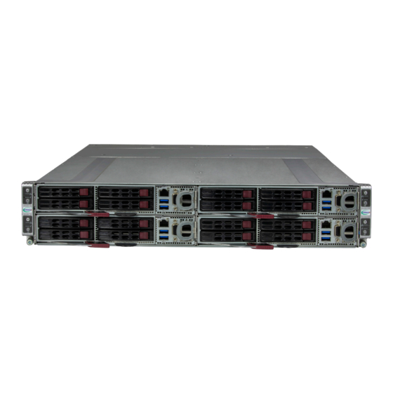
Chapter 1: Introduction System: Front View The CSE-GT214BF-R2K21BP2 is a 2U chassis that supports four hot-pluggable nodes. Refer to Appendix B for additional specifications.The chassis front offers access to the storage drives, a control panel for each node, four pullout service tags, and two thumbscrews. Control Panels for Node A (bottom) Control Panels for Node C (bottom) USB Ports... -
Page 12: System: Rear View
A+ Server AS -2115GT-HNTF User's Manual System: Rear View The illustration below shows the features on the rear of the chassis. PWS1 PWS2 Locking Clip Locking Clip Locking Lever Locking Lever Figure 1-3. System Rear View Rear Chassis Features Feature... -
Page 13: Network Ports
Note: The GrandTwin IO card is sold separately, but must be added to meet the minimum complete system requirements. For the complete support list, please check the Supermicro website. GrandTwin I/O Card Networking Add-on Card Options... -
Page 14: Motherboard Layout
A+ Server AS -2115GT-HNTF User's Manual 1.5 Motherboard Layout Below is a layout of the H13SST-G with jumper, connector and LED locations shown. See the table on the following page for descriptions. For detailed descriptions, pinout information and jumper settings, refer to... -
Page 15: Quick Reference Table
Chapter 1: Introduction Quick Reference Table Jumper Description Default Setting JBT1 CMOS Clear Open (Normal) JSATA1 Hybrid MCIO select Pins 2-3 (SATA) Description Status LED_PWR Power LED Solid Green: Power On LEDBMC BMC Heartbeat LED Green: Blinking (BMC normal), Green: Fast blinking (BMC initializing) Connector Description JNCSI1... -
Page 16: Block Diagram
A+ Server AS -2115GT-HNTF User's Manual Block Diagram H13SST-G FRONT I/O IPMI LAN RJ45 AMD SP5 Rev. 1.02 TS3L500AE COM1 RTL8211F USB 3.0 DDR4 AST2600 BMC ROM USB3.0 [1:0] USB2.0 HUB1 [0] IMPEL PLUS USB2.0 [1] PCIE x16 EMMC HUB 1x4... -
Page 17: Chapter 2 Server Installation
Chapter 2: Server Installation Chapter 2 Server Installation 2.1 Overview This chapter provides advice and instructions for mounting your system in a server rack. If your system is not already fully integrated with processors, system memory etc., refer to Chapter 4 for details on installing those specific components. -
Page 18: Server Precautions
A+ Server AS -2115GT-HNTF User's Manual • Always make sure the rack is stable before extending a server or other component from the rack. • You should extend only one server or component at a time - extending two or more simul- taneously may cause the rack to become unstable. -
Page 19: Circuit Overloading
Chapter 2: Server Installation Circuit Overloading Consideration should be given to the connection of the equipment to the power supply circuitry and the effect that any possible overloading of circuits might have on overcurrent protection and power supply wiring. Appropriate consideration of equipment nameplate ratings should be used when addressing this concern. -
Page 20: Installing The Rails
A+ Server AS -2115GT-HNTF User's Manual 2.3 Installing the Rails This section provides information on installing the chassis into a rack unit with the rails provided. There are a variety of rack units on the market, which may mean that the assembly procedure will differ slightly from the instructions provided. -
Page 21: Installing The Rails On A Rack
Chapter 2: Server Installation Installing the Rails on a Rack 1. Loosen the adjusting screw to allow the rear section to slide in the front section. 2. Push the small hooks on the front section of the rail into the holes on the front post of the rack and then down, until the spring-loaded pegs snap into the rack holes. -
Page 22: Chassis Installation
A+ Server AS -2115GT-HNTF User's Manual Chassis Installation Slide the chassis into the rack so that the bottom of the chassis slides onto the bottom lip of the rails. Figure 2-3. Sliding the Chassis into the Rack Stability hazard. The rack stabilizing mechanism must be in place, or the rack must be bolted to the floor before you slide the unit out for servicing. -
Page 23: Chapter 3 Maintenance And Component Installation
Chapter 3: Maintenance and Component Installation Chapter 3 Maintenance and Component Installation This chapter provides instructions on installing and replacing main system components. To prevent compatibility issues, only use components that match the specifications and/or part numbers given. Installation or replacement of most components require that power first be removed from the system. -
Page 24: Accessing The System
A+ Server AS -2115GT-HNTF User's Manual 3.2 Accessing the System Removing a Computing Node Drawer Latch Lever Latch Lever Latch Lever Latch Lever Figure 3-1. Removing a Node Tray Removing a Node 1. Use the operating system to power down the node. -
Page 25: Removing The Chassis Cover
Chapter 3: Maintenance and Component Installation Removing the Chassis Cover You can access some chassis components, such as fans, by removing the cover. Removing the Chassis Cover 1. Remove the four screws securing the cover to the chassis. 2. Slide the cover toward the rear of the chassis. 3. -
Page 26: Static-Sensitive Devices
A+ Server AS -2115GT-HNTF User's Manual 3.3 Static-Sensitive Devices Electrostatic Discharge (ESD) can damage electronic com ponents. To prevent damage to your motherboard, it is important to handle it very carefully. The following measures are generally sufficient to protect your equipment from ESD. -
Page 27: Processor And Heatsink Installation
CPU socket cap is in place and none of the socket pins are bent; otherwise, contact your retailer immediately. • Refer to the Supermicro website for updates on CPU support. Installing the Processor and Heatsink 1. Unscrew the screw #1 holding down the force frame. - Page 28 A+ Server AS -2115GT-HNTF User's Manual 2. The spring-loaded force frame will raise up after the screw securing it (#1) is removed. Gently allow it to lift up to its stopping position. Force Frame 3. Lift the rail frame up by gripping the lift tabs near the front end of the rail frame. While keeping a secure grip of the rail frame, lift it to a position so you can do the next step of removing the external cap.
- Page 29 Chapter 3: Maintenance and Component Installation 4. Remove the external cap from the rail frame by pulling it upwards through the rail guides on the rail frame. External Cap 5. The CPU package is shipped from the factory with the carrier frame pre-assembled. Grip the handle of the carrier frame/CPU package assembly from its shipping tray, and while gripping the handle, align the flanges of the carrier frame onto the rails of the rail frame so its pins will be at the bottom when the rail frame is lowered later.
- Page 30 A+ Server AS -2115GT-HNTF User's Manual Note: You can only install the CPU inside the socket in one direction with the handle at the top. Make sure that it is properly inserted into the CPU socket before closing the rail frame plate.
- Page 31 Chapter 3: Maintenance and Component Installation 8. Gently lower the rail frame down onto the socket until the latches on the rail frame engage with the socket housing and it rests in place. DO NOT force it into place! 9. The force frame is spring loaded and has to be held in place before it is secured. Use a torque screwdriver, set it at 12.5~15.0 kgf-cm (10.85~13.01 lbf-in) with a Torx T20 screw head bit, to prevent damage to the CPU.
- Page 32 A+ Server AS -2115GT-HNTF User's Manual 10. Replace and tighten the screws in the same order you removed them. When finished, the force frame will be secure over both the rail frame and CPU package. 11. After the force frame is secured and the CPU package is in place, now you must install the heatsink to the frame.
- Page 33 Chapter 3: Maintenance and Component Installation 12. Using a diagonal pattern, tighten the six screws down on the heatsink in a clockwise fashion till it is secure. The heatsink will now be secured and you have finished installing the processor and heatsink onto the motherboard. Repeat this procedure for any remaining CPU sockets on the motherboard.
- Page 34 A+ Server AS -2115GT-HNTF User's Manual Removing the Processor and Heatsink 1. Remove the heatsink attached to the top of the CPU package by reversing the installation procedure. 2. Clean the thermal grease left by the heatsink on the CPU package lid to limit the risk of it contaminating the CPU package land pads or contacts in the socket housing.
-
Page 35: Memory
The H13SST-G supports up to 3TB of ECC DDR5 4800 MT/s speed, RDIMM/LRDIMM/3DS memory in 12 slots. Refer to the table below for additional memory information. Note: Check the Supermicro website for possible updates to memory support. DIMM Population Guide Channel CPU1 &... -
Page 36: Dimm Module Population Sequence
A+ Server AS -2115GT-HNTF User's Manual DIMM Module Population Sequence • It is recommended that DDR5 DIMM modules of the same type, size and speed should be installed. • The motherboard will support odd-numbered modules (1 or 3 modules installed). However, to achieve the best memory performance, fully populate the motherboard with validated memory modules. -
Page 37: Dimm Installation
Chapter 3: Maintenance and Component Installation DIMM Installation 1. Insert the desired number of DIMMs into the memory slots, there is no specific sequence or order required. 2. Push the release tabs outwards on both ends of the DIMM slot to unlock it. Receptive Point 3. -
Page 38: Motherboard Battery
A+ Server AS -2115GT-HNTF User's Manual Motherboard Battery The motherboard uses non-volatile memory to retain system information when system power is removed. This memory is powered by a lithium battery residing on the motherboard. Replacing the Battery Begin by removing power from the system as described in Section 3.1. -
Page 39: Chassis Components
Safe to remove NVMe device Status LED Amber Blinking at 1Hz Do not remove NVMe device Note: Enterprise level hard disk drives are recommended for use in Supermicro chassis and servers. For information on recommended HDDs, visit the Supermicro website product pages at www.supermicro.com/products. -
Page 40: Drive Configuration
A+ Server AS -2115GT-HNTF User's Manual Drive Configuration The CSE-GT214BF-R2K21BP2 chassis contains four separate computing node drawers, each with its own motherboard. Each node controls a set of four drives (optional storage kit required). If a node drawer is pulled out of the chassis, the drives associated with that node will power down. -
Page 41: Removing/Installing Drives
Chapter 3: Maintenance and Component Installation Removing/Installing Drives Removing a Drive Carrier from the Chassis 1. Press the release button on the drive carrier. This extends the drive carrier handle. 2. Use the handle to pull the carrier out of the chassis. Caution: Except for short periods of time (swapping drives), do not operate the server with the drive carriers removed from the bays, regardless of how many drives are installed, for proper airflow. - Page 42 A+ Server AS -2115GT-HNTF User's Manual Installing a 2.5" Hard Drive 1. Place the hard drive carrier on a flat surface. 2. Remove the dummy drive, which comes pre-installed in the drive carrier, by removing the two locking tabs securing the dummy drive to the carrier.
- Page 43 Chapter 3: Maintenance and Component Installation 7. Insert the drive carrier into the chassis drive bay, keeping the carrier oriented so that the hard drive is on the top of the carrier and the release button is on the right side. When the carrier reaches the back of the drive bay, the release handle will retract.
-
Page 44: Hot-Swap For Nvme Drives
A+ Server AS -2115GT-HNTF User's Manual Hot-Swap for NVMe Drives Supermicro servers support NVMe surprise hot-swap. For even better data security, NVMe orderly hot-swap is recommended. NVMe drives can be ejected and replaced remotely using BMC. Ejecting a Drive 1. BMC > System > Storage Monitoring > Physical View 2. -
Page 45: Checking The Temperature Of An Nvme Drive
BMC > Sensor Reading – Shows the single highest temperature among all the NVMe drives. AIOM Card The Supermicro Advanced Input/Output Module (AIOM) card provides options for network connection. It is inserted into an AIOM slot on the motherboard tray (optional AIOM kit required). -
Page 46: I/O Card
A+ Server AS -2115GT-HNTF User's Manual I/O Card The I/O card provides options for input/output connections for different devices. It is inserted into the I/O slot on the motherboard tray. Removing the I/O Card 1. Loosen and remove the screw on the right side of the motherboard tray. -
Page 47: System Cooling
Chapter 3: Maintenance and Component Installation 3.7 System Cooling Fans Fan speed is controlled by a system temperature setting in BMC. If a fan fails, the remaining fans will ramp up to full speed. Replace any failed fan at your earliest convenience with the same type and model. -
Page 48: Installing The Air Shroud
A+ Server AS -2115GT-HNTF User's Manual Installing the Air Shroud The system requires air shrouds for each node to maximize airflow efficiency. The motherboard, any expansion cards, and all components must be installed in the node tray. Place the air shroud as pictured and secure with the screws. -
Page 49: Power Supply
3.8 Power Supply The chassis features dual redundant power supplies. Please exchange the power modules within one minute. New units can be ordered directly from Supermicro or authorized distributors. These power supplies are auto-switching capable. This feature enables them to automatically sense the input voltage and operate at a 100-120v or 180-240v. -
Page 50: Bmc Reset
A+ Server AS -2115GT-HNTF User's Manual 3.9 BMC Reset The BMC can be reset using the button on the front control panel or on the chassis rear. • Reset – Press and hold the button. After six seconds, the LED blinks at 2Hz. The BMC resets and the reset duration is ~250 ms. -
Page 51: Chapter 4 Motherboard Connections
Chapter 4: Motherboard Connections Chapter 4 Motherboard Connections This section describes the connections, jumpers and LED indicators on the motherboard and provides pinout definitions. Not all connections are required. A motherboard layout indicating component locations may be found in Chapter Please review the Safety Precautions in Appendix A before installing or removing components. -
Page 52: Headers And Connectors
A+ Server AS -2115GT-HNTF User's Manual 4.2 Headers and Connectors 4-pin External BMC I2C Header A System Management Bus header for IPMI 2.0 is located at JIPMB1. Connect a cable to this header to use the IPMB I C connection on your system. Refer to the table below for pin definitions. -
Page 53: Jumper Settings
Chapter 4: Motherboard Connections 4.3 Jumper Settings How Jumpers Work To modify the operation of the motherboard, jumpers can be used to choose between optional settings. Jumpers create shorts between two pins to change the function of the connector. Pin #1 is identified with a thicker border line on the printed circuit board. See the diagram below for an example of jumping pins 1 and 2. - Page 54 A+ Server AS -2115GT-HNTF User's Manual JSATA1 The 3-pin jumper at JSATA1 provides the option to switch the hybrid port (JMCIO5) between SATA/NVMe. Refer to the table below for pin definitions. JSATA1 Pin Definitions Pin# Definition Auto (Depends on system configuration)
-
Page 55: Led Indicators
Chapter 4: Motherboard Connections 4.4 LED Indicators Onboard Power LED LED_PWR is an onboard power LED. When this LED is lit, it means system is in power-on state, and the onboard power status is ok. Turn off the system and unplug the power cord before removing or installing components. -
Page 56: Chapter 5 Software
1. Create a method to access the Microsoft Windows installation ISO file. That can be a USB flash or media drive. 2. Go to the Supermicro web page for your motherboard and click on "Download the Latest Drivers and Utilities", select the proper driver, and copy it to a USB flash drive. - Page 57 Chapter 5: Software 4. During Windows Setup, continue to the dialog where you select the drives on which to install Windows. If the disk you want to use is not listed, click on “Load driver” link at the bottom left corner. Figure 5-2.
-
Page 58: Driver Installation
The Supermicro website contains drivers and utilities for your system at https://www. supermicro.com/wdl/. Some of these must be installed, such as the chipset driver. After accessing the website, go into the CDR_Images (in the parent directory of the above link) and locate the ISO file for your motherboard. Download this file to a USB flash or media drive. -
Page 59: Superdoctor ® 5
5.3 SuperDoctor ® The Supermicro SuperDoctor 5 is a program that functions in a command-line or web-based interface for Windows and Linux operating systems. The program monitors such system health information as CPU temperature, system voltages, system power consumption, fan speed, and provides alerts via email or Simple Network Management Protocol (SNMP). -
Page 60: Ipmi
A+ Server AS -2115GT-HNTF User's Manual 5.4 IPMI The H13SST-G supports the Intelligent Platform Management Interface (IPMI). IPMI provides remote access, monitoring and management through the baseboard management controller (BMC) and other management controllers distributed among different system modules.There are several BIOS settings that are related to IPMI. -
Page 61: Appendix A Standardized Warning Statements For Ac Systems
Supermicro's Technical Support department for assistance. Only certified technicians should attempt to install or configure components. Read this appendix in its entirety before installing or configuring components in the Supermicro chassis. These warnings may also be found on our website at http://www.supermicro.com/about/... - Page 62 Appendix A: Standardized Warning Statements Warnung WICHTIGE SICHERHEITSHINWEISE Dieses Warnsymbol bedeutet Gefahr. Sie befinden sich in einer Situation, die zu Verletzungen führen kann. Machen Sie sich vor der Arbeit mit Geräten mit den Gefahren elektrischer Schaltungen und den üblichen Verfahren zur Vorbeugung vor Unfällen vertraut. Suchen Sie mit der am Ende jeder Warnung angegebenen Anweisungsnummer nach der jeweiligen Übersetzung in den übersetzten Sicherheitshinweisen, die zusammen mit diesem Gerät ausgeliefert wurden.
- Page 63 A+ Server AS -2115GT-HNTF User's Manual . ٌ ا ك ً ف حالة و ٌ يك أى تتسبب ف اصابة جسذ ة ٌ هذا الزهز ع ٌ خطز !تحذ ز قبل أى تعول عىل أي هعذات،يك عىل علن بالوخاطز ال ا ٌجوة عي الذوائز...
- Page 64 Appendix A: Standardized Warning Statements Warnung Vor dem Anschließen des Systems an die Stromquelle die Installationsanweisungen lesen. ¡Advertencia! Lea las instrucciones de instalación antes de conectar el sistema a la red de alimentación. Attention Avant de brancher le système sur la source d'alimentation, consulter les directives d'installation. .יש...
- Page 65 A+ Server AS -2115GT-HNTF User's Manual Warnung Dieses Produkt ist darauf angewiesen, dass im Gebäude ein Kurzschluss- bzw. Überstromschutz installiert ist. Stellen Sie sicher, dass der Nennwert der Schutzvorrichtung nicht mehr als: 250 V, 20 A beträgt. ¡Advertencia! Este equipo utiliza el sistema de protección contra cortocircuitos (o sobrecorrientes) del edificio.
- Page 66 Appendix A: Standardized Warning Statements Power Disconnection Warning Warning! The system must be disconnected from all sources of power and the power cord removed from the power supply module(s) before accessing the chassis interior to install or remove system components. 電源切断の警告...
- Page 67 A+ Server AS -2115GT-HNTF User's Manual אזהרה מפני ניתוק חשמלי !אזהרה יש לנתק את המערכת מכל מקורות החשמל ויש להסיר את כבל החשמלי מהספק .לפני גישה לחלק הפנימי של המארז לצורך התקנת או הסרת רכיבים يجب فصم اننظاو من جميع مصادر انطاقت وإ ز انت سهك انكهرباء من وحدة امداد...
- Page 68 Appendix A: Standardized Warning Statements Attention Il est vivement recommandé de confier l'installation, le remplacement et la maintenance de ces équipements à des personnels qualifiés et expérimentés. !אזהרה .צוות מוסמך בלבד רשאי להתקין, להחליף את הציוד או לתת שירות עבור הציוד واملدربيه...
- Page 69 A+ Server AS -2115GT-HNTF User's Manual Warnung Diese Einheit ist zur Installation in Bereichen mit beschränktem Zutritt vorgesehen. Der Zutritt zu derartigen Bereichen ist nur mit einem Spezialwerkzeug, Schloss und Schlüssel oder einer sonstigen Sicherheitsvorkehrung möglich. ¡Advertencia! Esta unidad ha sido diseñada para instalación en áreas de acceso restringido. Sólo puede obtenerse acceso a una de estas áreas mediante la utilización de una herramienta especial,...
- Page 70 Appendix A: Standardized Warning Statements Battery Handling Warning! There is the danger of explosion if the battery is replaced incorrectly. Replace the battery only with the same or equivalent type recommended by the manufacturer. Dispose of used batteries according to the manufacturer's instructions 電池の取り扱い...
- Page 71 A+ Server AS -2115GT-HNTF User's Manual هناك خطر من انفجار يف حالة اسحبذال البطارية بطريقة غري صحيحة فعليل اسحبذال البطارية فقط بنفس النىع أو ما يعادلها مام أوصث به الرشمة املصنعة جخلص من البطاريات املسحعملة وفقا لحعليامت الرشمة الصانعة 경고! 배터리가...
- Page 72 Appendix A: Standardized Warning Statements ¡Advertencia! Puede que esta unidad tenga más de una conexión para fuentes de alimentación. Para cortar por completo el suministro de energía, deben desconectarse todas las conexiones. Attention Cette unité peut avoir plus d'une connexion d'alimentation. Pour supprimer toute tension et tout courant électrique de l'unité, toutes les connexions d'alimentation doivent être débranchées.
- Page 73 A+ Server AS -2115GT-HNTF User's Manual Backplane Voltage Warning! Hazardous voltage or energy is present on the backplane when the system is operating. Use caution when servicing. バックプレーンの電圧 システムの稼働中は危険な電圧または電力が、 バックプレーン上にかかっています。 修理する際には注意ください。 警告 当系统正在进行时,背板上有很危险的电压或能量,进行维修时务必小心。 警告 當系統正在進行時,背板上有危險的電壓或能量,進行維修時務必小心。 Warnung Wenn das System in Betrieb ist, treten auf der Rückwandplatine gefährliche Spannungen oder Energien auf.
- Page 74 Appendix A: Standardized Warning Statements هناك خطز مه التيار الكهزبايئ أوالطاقة املىجىدة عىل اللىحة عندما يكىن النظام يعمل كه حذ ر ا عند خدمة هذا الجهاس 경고! 시스템이 동작 중일 때 후면판 (Backplane)에는 위험한 전압이나 에너지가 발생 합니다. 서비스 작업 시 주의하십시오. Waarschuwing Een gevaarlijke spanning of energie is aanwezig op de backplane wanneer het systeem in gebruik is.
- Page 75 A+ Server AS -2115GT-HNTF User's Manual תיאום חוקי החשמל הארצי !אזהרה .התקנת הציוד חייבת להיות תואמת לחוקי החשמל המקומיים והארציים تركيب املعدات الكهربائية يجب أن ميتثل للقىاويه املحلية والىطىية املتعلقة بالكهرباء 경고! 현 지역 및 국가의 전기 규정에 따라 장비를 설치해야 합니다.
- Page 76 Appendix A: Standardized Warning Statements Attention La mise au rebut ou le recyclage de ce produit sont généralement soumis à des lois et/ou directives de respect de l'environnement. Renseignez-vous auprès de l'organisme compétent. סילוק המוצר !אזהרה .סילוק סופי של מוצר זה חייב להיות בהתאם להנחיות וחוקי המדינה التخلص...
- Page 77 A+ Server AS -2115GT-HNTF User's Manual Warnung Gefährlich Bewegende Teile. Von den bewegenden Lüfterblätter fern halten. Die Lüfter drehen sich u. U. noch, wenn die Lüfterbaugruppe aus dem Chassis genommen wird. Halten Sie Finger, Schraubendreher und andere Gegenstände von den Öffnungen des Lüftergehäuses entfernt.
- Page 78 Verbindungskabeln, Stromkabeln und/oder Adapater, die Ihre örtlichen Sicherheitsstandards einhalten. Der Gebrauch von anderen Kabeln und Adapter können Fehlfunktionen oder Feuer verursachen. Die Richtlinien untersagen das Nutzen von UL oder CAS zertifizierten Kabeln (mit UL/CSA gekennzeichnet), an Geräten oder Produkten die nicht mit Supermicro gekennzeichnet sind.
- Page 79 .قيرح وأ لطع يف ببستي دق ىرخأ تالوحمو تالباك يأ مادختسا .ميلسلا سباقلاو لصوملا مجح لبق نم ةدمتعملا تالباكلا مادختسا تادعملاو ةيئابرهكلا ةزهجألل ةمالسلا نوناق رظحيUL وأCSA ( ةمالع لمحت يتلاوUL/CSA) لبق نم ةددحملاو ةينعملا تاجتنملا ريغ ىرخأ تادعم يأ عمSupermicro.
- Page 80 사항을 준수하여 제공되거나 지정된 연결 혹은 구매 케이블, 전원 케이블 및 AC 어댑터를 사용하십시오. 다른 케이블이나 어댑터를 사용하면 오작동이나 화재가 발생할 수 있습니다. 전기 용품 안전법은 UL 또는 CSA 인증 케이블 (코드에 UL / CSA가 표시된 케이블)을 Supermicro 가 지정한 제품 이외의 전기 장치에 사용하는 것을 금지합니다. Stroomkabel en AC-Adapter...
-
Page 81: Appendix B System Specifications
Appendix B: System Specifications Appendix B System Specifications Processor Support AMD EPYC 9004 series processors in Socket SP5 Chipset System on Chip (SoC) BIOS AMI 32MB SPI Flash EEPROM Memory (per node) Up to 3TB registered ECC DDR5 4800 MT/s speed in 12 DIMM slots Storage Drives (per node) Front hot-swappable drives: Supports up to four SATA/SAS/NVMe drives depending on selected enablement kits... - Page 82 A+ Server AS -2115GT-HNTF User's Manual Operating Environment Operating Temperature: 10º to 35º C (50º to 95º F) Non-operating Temperature: -30º to 60º C (-22º to 140º F) Operating Relative Humidity: 8% to 80% (non-condensing) Non-operating Relative Humidity: 8% to 90% (non-condensing)
Need help?
Do you have a question about the A+ Server AS -2115GT-HNTF and is the answer not in the manual?
Questions and answers