Table of Contents
Advertisement
Quick Links
Advertisement
Table of Contents

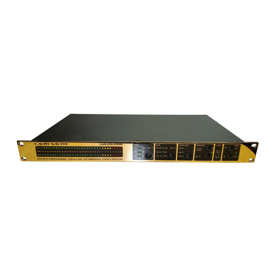
Summary of Contents for Lavry Savitr AD-24-200
- Page 1 AD-24-200 Savitr...
- Page 2 Lavry Engineering, Inc. P.O. Box 4602 Rolling Bay, WA 98061 www.lavryengineering.com October 1, 2021 Version 1.4...
-
Page 3: Table Of Contents
Warranty ............................................15 CAUTION The front panel of the Lavry Savitr is plated with 24 karat gold, which is vulnerable to abrasion. When shipping this unit, protect the front panel with a non-abrasive cloth. For safety, users should not attempt to service or repair the unit unless given specific instructions to do so by Lavry Support staff-members (Users will be advised to power off, and unplug the unit before removing the top-cover and to replace the top cover before plugging and powering on the unit). -
Page 4: Rear Panel
REAR PANEL AC Power section AC Power Inlet The Savitr power supply accepts AC power in the range of 90-264 Volts at 47-63 Hertz. The power supply adjusts automatically for proper operation within this voltage & frequency range. The included power cord has a push-button locking feature. Once inserted, you must press the yellow button to remove the power cable! This unit can also be powered via a standard IEC C13 power cord rated for the supplied AC voltage. - Page 5 ANALOG INPUT section LEFT Input connector RIGHT Input connector These 2 locking female XLRs accept Balanced or Unbalanced analog audio signals. The internal GAIN range: 0 dB to 7 dB To achieve Full-scale; balanced input range: 17-24 dBu To achieve Full-scale;...
- Page 6 AUX DIGITAL OUTPUT section SYNC INPUT switch UP position: SYNC INPUT is set to receive WORD CLOCK. DOWN position: SYNC INPUT is set to receive AES. SYNC INPUT connector This BNC input is use to lock the AUX output to an external clock source (Word Clock or AES). The input is internally terminated by 75Ω.
-
Page 7: Front Panel (Start-Up Sequence)
FRONT PANEL (START-UP SEQUENCE) The front panel layout consists of the METER, and USER CONTROL SETTINGS. METER The meter displays digital audio output peak levels. USER SETTINGS groups User control settings consist of switches, LED indicators (lamps) and trim pots. STARTUP sequence During calibration, the METER runs a visual sweep from left to right, illuminating one pair of lamps at a time. -
Page 8: Front Panel (Operation Mode)
FRONT PANEL (OPERATION MODE) Enable lamp EDIT mode: ON OPERATION mode: OFF Enable switch A sustained press of this switch enables EDIT mode. The ENABLE lamp will turn ON when this change occurs. switch This switch cycles through the illumination levels of the METER lamps. switch This switch cycles through the illumination levels of the USER CONTROL SETTINGS groups. - Page 9 EDIT control section Enable switch To switch between OPERATION and EDIT mode, press and hold this switch until the ENABLE lamp changes. In EDIT mode the unit will automatically exit to OPERATION mode after a short idle time. Enable lamp ...
- Page 10 SAMPLE RATE lamps There are 6 lamps labeled with numbers 44.1, 88.2, 96, 176.4, and 192. These refer to sample rates in kHz. Depending on clock mode, these lamps function differently. INTERNAL clocking mode ON: displays the active clock rate. ...
- Page 11 SOFT SAT control section SOFT SAT switch This switch will SELECT a SOFT SATURATION level. 3 lamps These lamps indicate and control application of 4 levels of SOFT SATURATION to the audio signal: OFF: No Saturation. ON: Displays level of SOFT SATURATION. ...
- Page 12 GAIN control section INPUT TRIM potentiometers The L and R potentiometers control INPUT GAIN for the LEFT and RIGHT analog channels. Using a small, flat-head screwdriver: CLOCKWISE rotation INCREASES GAIN. These trim pots provide 0-7dB of GAIN. djustment may require many rotations FULL-SCALE signal for BALANCED inputs is 24dBu.
-
Page 13: Technical Specifications
TECHNICAL SPECIFICATIONS THD+N (0 dB Internal Gain) Analog Input Level Source Frequency Gain 20 kHz Bandwidth 40 kHz Bandwidth -1 dBFS 1 kHz 0 dB -110 dBFS 0.00032 %FS -107 dBFS 0.00045 %FS -0.1 dBFS 20 Hz to 20 kHz 0 dB -109 dBFS 0.00035 %FS... -
Page 14: Appendix A- Ac Power, Power Cord, And Fuse Access
APPENDIX A- AC POWER, POWER CORD, AND FUSE ACCESS AC Power and Power Cord The Lavry Savitr AD-24-200 power supply accepts AC power in the range of 90-264 Volts at 47-63 Hertz. The power supply adjusts automatically for proper operation with AC power within this voltage &... -
Page 15: Warranty
WARRANTY Subject to the conditions set forth below, for one year after the original purchase date of the product, Lavry Engineering will repair the product free of charge in the United States in the event of a defect in materials or workmanship.
Need help?
Do you have a question about the Savitr AD-24-200 and is the answer not in the manual?
Questions and answers