
Related Manuals for Innova MATRIX MK II+


Summary of Contents for Innova MATRIX MK II+
- Page 1 Operation and Maintenance Manual P.O. BOX 390 Tel.: +47 51 96 17 00 post@innova.no 4067 Stavanger, Norway Fax.: +47 51 96 17 01 www.innova.no...
-
Page 2: Table Of Contents
Innova – Matrix MK II+ Date 12.12.2017 Operation and Maintenance Manual Page 2 of 74 Project No.: Document No.: Rev. 604653 MAN-000015294 Table of Contents INTRODUCTION ............................. 5 ..........................5 ENERAL DESCRIPTION SAFETY ................................6 ............................ 6 LECTRICAL SAFETY ............................6 PRECAUTIONS ............................ - Page 3 Innova – Matrix MK II+ Date 12.12.2017 Operation and Maintenance Manual Page 3 of 74 Project No.: Document No.: Rev. 604653 MAN-000015294 5.2.11 DV camera (optional) ........................29 ........................30 OPSIDE ONSOLE SYSTEM APPENDIX A ..............................32 POWER– I ..........................32 NPUT POWER FIBRE –F...
- Page 4 Innova – Matrix MK II+ Date 12.12.2017 Operation and Maintenance Manual Page 4 of 74 Project No.: Document No.: Rev. 604653 MAN-000015294 C9 – 100M 6.16 /TTL RS232 I ................58 THERNET NTERFACE 6.16.1 Subsea ............................... 58 6.16.2 Topside .............................. 59 C10 –...
-
Page 5: Introduction
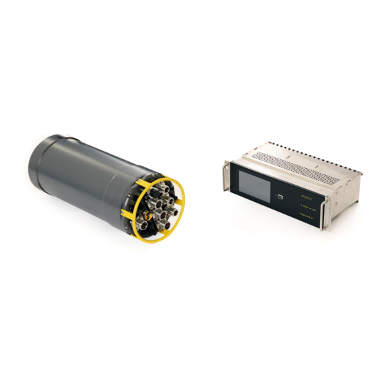
The Matrix MKII+ is a fibre optic multiplexer system with power control of external devices. Based on Innova’s LINK fibre-optical multiplexer technology, the Matrix MKII+ has the highest data capacity on the market, while providing up to 1200W DC power to sensors and external equipment. -
Page 6: Safety
Innova – Matrix MK II+ Date 12.12.2017 Operation and Maintenance Manual Page 6 of 74 Project No.: Document No.: Rev. 604653 MAN-000015294 2 Safety Electrical safety Both the Matrix rack unit and the canister must be connected to mains protective earth. -
Page 7: System Set-Up
Innova – Matrix MK II+ Date 12.12.2017 Operation and Maintenance Manual Page 7 of 74 Project No.: Document No.: Rev. 604653 MAN-000015294 3 System set-up Installation and configuration. The Matrix MKII+ system is designed to be simple to interface to any ROV system, requiring one single mode fibre for communication and 85-264VAC power to the subsea unit. -
Page 8: Installation Of Topside Unit
Innova – Matrix MK II+ Date 12.12.2017 Operation and Maintenance Manual Page 8 of 74 Project No.: Document No.: Rev. 604653 MAN-000015294 Figure 1 – Transport box with content The dummy connector kit is located in a separate transport case. The fibre components and adapter is found in a small plastic case. -
Page 9: Installation Of Canister
Innova – Matrix MK II+ Date 12.12.2017 Operation and Maintenance Manual Page 9 of 74 Project No.: Document No.: Rev. 604653 MAN-000015294 Figure 2 – Topside unit back panel To provide power to the system, turn on the power switch on the back of the unit, beside the IEC power inlet. -
Page 10: Fibre-Optic Connection
Innova – Matrix MK II+ Date 12.12.2017 Operation and Maintenance Manual Page 10 of 74 Project No.: Document No.: Rev. 604653 MAN-000015294 The connector is also supplied with an adapter to fit a Burton 5506 shellsize 20 type connector interface. Other adapters can be provided on request. -
Page 11: Connecting External Equipment
Innova – Matrix MK II+ Date 12.12.2017 Operation and Maintenance Manual Page 11 of 74 Project No.: Document No.: Rev. 604653 MAN-000015294 Connecting external equipment Before external equipment is connected, some planning is recommended to ensure optimal use of the available data channels. - Page 12 Innova – Matrix MK II+ Date 12.12.2017 Operation and Maintenance Manual Page 12 of 74 Project No.: Document No.: Rev. 604653 MAN-000015294 FIBRE FIBRE: Seacon OPT-F-1-SM Seacon OPT-G-4-SM (optional) FMC Schilling Fibre connnector (optional) POWER Seacon 5506-2006 Interfacing details of each connector, including pinout for each connector topside and subsea are found in Appendix A.
- Page 13 Innova – Matrix MK II+ Date 12.12.2017 Operation and Maintenance Manual Page 13 of 74 Project No.: Document No.: Rev. 604653 MAN-000015294 As a general rule, the C1 and C2 Ethernet channels should be used for multi beam echo sounders requiring Layer 2 Gigabit Ethernet, such as Reson 7125.
-
Page 14: System Configuration
Innova – Matrix MK II+ Date 12.12.2017 Operation and Maintenance Manual Page 14 of 74 Project No.: Document No.: Rev. 604653 MAN-000015294 System configuration 3.4.1 General The system is configured using the touch screen interface on the topside unit. On the screen, the left side buttons (CONTROL, LINK, STATUS, SETUP and ALARM) switches between different modes. -
Page 15: Configuring The Network Interface
Innova – Matrix MK II+ Date 12.12.2017 Operation and Maintenance Manual Page 15 of 74 Project No.: Document No.: Rev. 604653 MAN-000015294 3.4.2 Configuring the network interface If the topside unit is to be accessed via the web interface, the network interface needs to be set Note: The Config Port is only for the web interface and not for communication with subsea equipment. -
Page 16: Configuring The Outputs
Innova – Matrix MK II+ Date 12.12.2017 Operation and Maintenance Manual Page 16 of 74 Project No.: Document No.: Rev. 604653 MAN-000015294 3.4.3 Configuring the outputs Before powering up the subsea equipment, each output should be configured correctly according to the requirements of the connected devices. Please refer to section 3.3 for considerations on where and how to connect different types of equipment. - Page 17 Innova – Matrix MK II+ Date 12.12.2017 Operation and Maintenance Manual Page 17 of 74 Project No.: Document No.: Rev. 604653 MAN-000015294 Figure 8 - EDIT screen - Press the button representing the output you want to configure. The button is highlighted, and configuration alternatives are shown on the right side.
-
Page 18: Operation And Maintenance
Innova – Matrix MK II+ Date 12.12.2017 Operation and Maintenance Manual Page 18 of 74 Project No.: Document No.: Rev. 604653 MAN-000015294 4 Operation and maintenance Operation The system is operated via the touch screen interface on the topside unit, or the web interface if this is set up. -
Page 19: Pre-Dive Checks
Innova – Matrix MK II+ Date 12.12.2017 Operation and Maintenance Manual Page 19 of 74 Project No.: Document No.: Rev. 604653 MAN-000015294 Pre-dive checks The following should be performed prior to each dive: 1. Check that the subsea canister is properly mounted and connected to cathodic protection 2. -
Page 20: Maintenance, Storage And Transport
Anodizing touchup pen, or similar (Not applicable for titanium). If pitting corrosion is found near seal surfaces, the unit must be inspected for seal integrity prior to diving. Contact Innova or the local Innova representative for service. Prior to storage, the following should be performed: 1. -
Page 21: Troubleshooting
Innova – Matrix MK II+ Date 12.12.2017 Operation and Maintenance Manual Page 21 of 74 Project No.: Document No.: Rev. 604653 MAN-000015294 Troubleshooting Fault description Reason RS232 or RS485 on combined Wrong setting Check settings on Edit screen. port does not work. - Page 22 Innova – Matrix MK II+ Date 12.12.2017 Operation and Maintenance Manual Page 22 of 74 Project No.: Document No.: Rev. 604653 MAN-000015294 No LINK LED on topside No power on topside or Check power to cannister and unit. subsea bottle.
-
Page 23: Technical Description
- The fibre-optical multiplexer system - The power control system The fibre optical multiplexer is a based around Innova's LINK family of fibre mux boards, using a combination of video/serial data multiplexing and optical multiplexing to provide a number of transparent data channels over one singe fibre. -
Page 24: Technical Data
Innova – Matrix MK II+ Date 12.12.2017 Operation and Maintenance Manual Page 24 of 74 Project No.: Document No.: Rev. 604653 MAN-000015294 Technical data 5.2.1 Subsea Canister Aluminum Dimensions: L = 600 mm, Ø = 220 mm (Ø = 210mm in centre) -
Page 25: Subsea Canister Titanium Rev. 2
Innova – Matrix MK II+ Date 12.12.2017 Operation and Maintenance Manual Page 25 of 74 Project No.: Document No.: Rev. 604653 MAN-000015294 5.2.3 Subsea Canister titanium rev. 2 Dimensions: L = 588 mm, Ø = 220 mm (Ø = 210mm in centre) -
Page 26: System Description
Innova – Matrix MK II+ Date 12.12.2017 Operation and Maintenance Manual Page 26 of 74 Project No.: Document No.: Rev. 604653 MAN-000015294 5.2.5 System description The subsea control bottle is a one-atmospheric canister populated with the following components: • LINK Ethernet board •... -
Page 27: Earth Insulation Monitoring & Water Alarm
Innova – Matrix MK II+ Date 12.12.2017 Operation and Maintenance Manual Page 27 of 74 Project No.: Document No.: Rev. 604653 MAN-000015294 RS485 LINK C1 – Multibeam 1 48Vdc C2 – Multibeam 2 Power C3 – Multi Interface 24Vdc Ctrl C4 –... -
Page 28: Ethernet Channels
Innova – Matrix MK II+ Date 12.12.2017 Operation and Maintenance Manual Page 28 of 74 Project No.: Document No.: Rev. 604653 MAN-000015294 5.2.8 Ethernet channels The 4 channel Ethernet board connects the subsea Ethernet channels to the topside Ethernet system. The communication speed on channel 1 to 2 is set to 1Gbps and used for MBE's (C1 &... -
Page 29: Dv Camera (Optional)
Innova – Matrix MK II+ Date 12.12.2017 Operation and Maintenance Manual Page 29 of 74 Project No.: Document No.: Rev. 604653 MAN-000015294 Matrix Serial #1 Internally used C7 RS232 LINK C8 RS232 Matrix Serial C10 RS232 ELECTRIC C12 RS232 Board... -
Page 30: Topside Console System
Innova – Matrix MK II+ Date 12.12.2017 Operation and Maintenance Manual Page 30 of 74 Project No.: Document No.: Rev. 604653 MAN-000015294 Camera Video Signal Fiber LINK C4 – DV Camera 1 LINK C5 – DV Camera 2 FIBER C6 – DV Camera 3... - Page 31 Innova – Matrix MK II+ Date 12.12.2017 Operation and Maintenance Manual Page 31 of 74 Project No.: Document No.: Rev. 604653 MAN-000015294 Ethernet channels overview: Channel Connector output Function Speed MBE 1 1Gbps MBE 2 1Gbps C3 and C9 Multi-port (via switch)
-
Page 32: Power- Input Power
Innova – Matrix MK II+ Date 12.12.2017 Operation and Maintenance Manual Page 32 of 74 Project No.: Document No.: Rev. 604653 MAN-000015294 6 Appendix A Interface Details POWER– Input power Seacon 5506-2006 FUNCTION Protective Earth Protective Earth 110/230VAC-L1 110/230VAC-L1 110/230VAC-L2 110/230VAC-L2 Recommended mates for Seacon 5506-2006: Seacon 55A1-2006 or Seacon 5501-2006. -
Page 33: Fibre -Fibre Optical Connector
Innova – Matrix MK II+ Date 12.12.2017 Operation and Maintenance Manual Page 33 of 74 Project No.: Document No.: Rev. 604653 MAN-000015294 FIBRE –Fibre Optical connector Seacon OPT-F-1(1SM)-BCR FUNCTION Topside Comms (SM) Recommended mates for Seacon OPT-F-1: Seacon OPT-F-1-CCP P.O. BOX 390 Tel.: +47 51 96 17 00... -
Page 34: Fibre -Fibre Optical Connector (Optional)
Spare (MM) In the event of damage to the main fibre the spare fibre #2 can be connected. Please contact Innova for details. Optional: If the matrix system is ordered as a Multimode system the main fibre will be #3. -
Page 35: Fibre -Fmc Schilling Fibre Optical Connector (Optional)
Innova – Matrix MK II+ Date 12.12.2017 Operation and Maintenance Manual Page 35 of 74 Project No.: Document No.: Rev. 604653 MAN-000015294 FIBRE –FMC Schilling Fibre Optical connector (Optional) Schilling Fibre Connector FUNCTION Topside Comms (SM) P.O. BOX 390 Tel.: +47 51 96 17 00 post@innova.no... -
Page 36: C1 - Multibeam Interface
Innova – Matrix MK II+ Date 12.12.2017 Operation and Maintenance Manual Page 36 of 74 Project No.: Document No.: Rev. 604653 MAN-000015294 C1 – Multibeam interface 6.5.1 Subsea Power output: • Software switchable 48VDC or 24VDC • Fuse size settable in software, Max 6A •... -
Page 37: Topside
Innova – Matrix MK II+ Date 12.12.2017 Operation and Maintenance Manual Page 37 of 74 Project No.: Document No.: Rev. 604653 MAN-000015294 6.5.2 Topside C1 RX LED C1 TX LED C1 RS232 C1 Gbit jumper (default off) C1 Ethernet C1 PECL PECL (75 Ω) Interface... -
Page 38: C2 - Multibeam Interface
Innova – Matrix MK II+ Date 12.12.2017 Operation and Maintenance Manual Page 38 of 74 Project No.: Document No.: Rev. 604653 MAN-000015294 C2 – Multibeam interface 6.6.1 Subsea Power output: • Software switchable 48VDC or 24VDC • Fuse size settable in software, Max 6A •... -
Page 39: Topside
Innova – Matrix MK II+ Date 12.12.2017 Operation and Maintenance Manual Page 39 of 74 Project No.: Document No.: Rev. 604653 MAN-000015294 6.6.2 Topside C2 Gbit jumper (default off) C2 RX LED C2 TX LED C2 RS232 C2 Ethernet C1 PECL PECL (75 Ω) Interface... -
Page 40: C3 - Multi Interface Connector
Innova – Matrix MK II+ Date 12.12.2017 Operation and Maintenance Manual Page 40 of 74 Project No.: Document No.: Rev. 604653 MAN-000015294 C3 – Multi Interface connector Power output: • Hardware switchable 48VDC or 24VDC 150W Max (Not client accessable) •... -
Page 41: Topside
Innova – Matrix MK II+ Date 12.12.2017 Operation and Maintenance Manual Page 41 of 74 Project No.: Document No.: Rev. 604653 MAN-000015294 6.7.1 Topside C3 RS232/RS485 C3 RX LED C3 TX LED C3 Gbit jumper default off C3 Ethernet C3 TTL 5V... -
Page 42: C4 - Hd-Sdi Camera Interface (Optional)
Innova – Matrix MK II+ Date 12.12.2017 Operation and Maintenance Manual Page 42 of 74 Project No.: Document No.: Rev. 604653 MAN-000015294 C4 - HD-SDI Camera Interface (Optional) 6.8.1 Subsea Power output: • 24VDC • Fuse size settable in software, Max 2A •... -
Page 43: Topside
Innova – Matrix MK II+ Date 12.12.2017 Operation and Maintenance Manual Page 43 of 74 Project No.: Document No.: Rev. 604653 MAN-000015294 6.8.2 Topside C4 HD-SDI C4 RX LED C4 TX LED C4 RS232 HD-SDI (75 Ω) Interface RS232 Interface... -
Page 44: C4 - Analog Video Camera Interface (Optional)
Innova – Matrix MK II+ Date 12.12.2017 Operation and Maintenance Manual Page 44 of 74 Project No.: Document No.: Rev. 604653 MAN-000015294 C4 – Analog video Camera Interface (Optional) 6.9.1 Subsea Power output: • 24VDC • Fuse size settable in software, Max 2A •... -
Page 45: Topside
Innova – Matrix MK II+ Date 12.12.2017 Operation and Maintenance Manual Page 45 of 74 Project No.: Document No.: Rev. 604653 MAN-000015294 6.9.2 Topside C4 Analog Video C4 RX LED C4 TX LED C4 RS232 Analog video (75 Ω) RS232 Interface... -
Page 46: C5 - Hd-Sdi Camera Interface (Optional)
Innova – Matrix MK II+ Date 12.12.2017 Operation and Maintenance Manual Page 46 of 74 Project No.: Document No.: Rev. 604653 MAN-000015294 6.10 C5 - HD-SDI Camera Interface (Optional) 6.10.1 Subsea Power output: • 24VDC • Fuse size settable in software, Max 2A •... -
Page 47: Topside
Innova – Matrix MK II+ Date 12.12.2017 Operation and Maintenance Manual Page 47 of 74 Project No.: Document No.: Rev. 604653 MAN-000015294 6.10.2 Topside C5 HD-SDI C5 RX LED C5 TX LED C5 RS232 HD-SDI (75 Ω) Interface RS232 Interface... -
Page 48: C5 - Analog Video Camera Interface (Optional)
Innova – Matrix MK II+ Date 12.12.2017 Operation and Maintenance Manual Page 48 of 74 Project No.: Document No.: Rev. 604653 MAN-000015294 6.11 C5 – Analog video Camera Interface (Optional) 6.11.1 Subsea Power output: • 24VDC • Fuse size settable in software, Max 2A •... -
Page 49: Topside
Innova – Matrix MK II+ Date 12.12.2017 Operation and Maintenance Manual Page 49 of 74 Project No.: Document No.: Rev. 604653 MAN-000015294 6.11.2 Topside C5 Analog Video C5 RX LED C5 TX LED C5 RS232 Analog video (75 Ω) RS232 Interface... -
Page 50: C6 - Hd-Sdi Camera Interface (Optional)
Innova – Matrix MK II+ Date 12.12.2017 Operation and Maintenance Manual Page 50 of 74 Project No.: Document No.: Rev. 604653 MAN-000015294 6.12 C6 - HD-SDI Camera Interface (Optional) 6.12.1 Subsea Power output: • 24VDC • Fuse size settable in software, Max 2A •... -
Page 51: Topside
Innova – Matrix MK II+ Date 12.12.2017 Operation and Maintenance Manual Page 51 of 74 Project No.: Document No.: Rev. 604653 MAN-000015294 6.12.2 Topside C6 HD-SDI C6 RX LED C6 TX LED C6 RS232 HD-SDI (75 Ω) Interface RS232 Interface... -
Page 52: C6 - Analog Video Camera Interface (Optional )
Innova – Matrix MK II+ Date 12.12.2017 Operation and Maintenance Manual Page 52 of 74 Project No.: Document No.: Rev. 604653 MAN-000015294 6.13 C6 – Analog video Camera Interface (Optional) 6.13.1 Subsea Power output: • 24VDC • Fuse size settable in software, Max 2A •... -
Page 53: Topside
Innova – Matrix MK II+ Date 12.12.2017 Operation and Maintenance Manual Page 53 of 74 Project No.: Document No.: Rev. 604653 MAN-000015294 6.13.2 Topside C6 Analog Video C6 RX LED C6 TX LED C6 RS232 Analog video (75 Ω) RS232 Interface... -
Page 54: C7 - Rs232 Interface
Innova – Matrix MK II+ Date 12.12.2017 Operation and Maintenance Manual Page 54 of 74 Project No.: Document No.: Rev. 604653 MAN-000015294 6.14 C7 – RS232 Interface 6.14.1 Subsea Seacon MCBH8F FUNCTION RS232 0V RS232 Tx (Downlink) RS232 Rx (Uplink) Recommended mates for Seacon MCBH8F: Seacon MCIL8M P.O. -
Page 55: Topside
Innova – Matrix MK II+ Date 12.12.2017 Operation and Maintenance Manual Page 55 of 74 Project No.: Document No.: Rev. 604653 MAN-000015294 6.14.2 Topside C7 RX LED C7 TX LED C7 RS232 RS232 Interface RJ-45(7) Pin Function RS232 - 0V RS232 –... -
Page 56: C8 - Rs232 Interface
Innova – Matrix MK II+ Date 12.12.2017 Operation and Maintenance Manual Page 56 of 74 Project No.: Document No.: Rev. 604653 MAN-000015294 6.15 C8 – RS232 Interface 6.15.1 Subsea Seacon MCBH8F FUNCTION RS232 0V RS232 Tx (Downlink) RS232 Rx (Uplink) Recommended mates for Seacon MCBH8F: Seacon MCIL8M P.O. -
Page 57: Topside
Innova – Matrix MK II+ Date 12.12.2017 Operation and Maintenance Manual Page 57 of 74 Project No.: Document No.: Rev. 604653 MAN-000015294 6.15.2 Topside C8 RX LED C8 TX LED C8 RS232 RS232 Interface RJ-45(8) Pin Function RS232 - 0V RS232 –... -
Page 58: C9 - 100Mbps Ethernet/Ttl Or Rs232 Interface
Innova – Matrix MK II+ Date 12.12.2017 Operation and Maintenance Manual Page 58 of 74 Project No.: Document No.: Rev. 604653 MAN-000015294 6.16 C9 – 100Mbps Ethernet/TTL or RS232 Interface 6.16.1 Subsea Seacon MCBH8F OPTIONAL STANDARD FUNCTION FUNCTION TTL 5V (Same TTL split... -
Page 59: Topside
Innova – Matrix MK II+ Date 12.12.2017 Operation and Maintenance Manual Page 59 of 74 Project No.: Document No.: Rev. 604653 MAN-000015294 6.16.2 Topside C3 Gbit jumper (default off) C9 RX LED OPTIONAL C9 TX LED OPTIONAL C9 RS232 OPTIONAL... -
Page 60: C10 - Rs232 Interface With Ttl
Innova – Matrix MK II+ Date 12.12.2017 Operation and Maintenance Manual Page 60 of 74 Project No.: Document No.: Rev. 604653 MAN-000015294 6.17 C10 – RS232 Interface with TTL 6.17.1 Subsea Seacon MCBH8F FUNCTION TTL 5V(Same TTL split out on both C10 and C9) -
Page 61: Topside
Innova – Matrix MK II+ Date 12.12.2017 Operation and Maintenance Manual Page 61 of 74 Project No.: Document No.: Rev. 604653 MAN-000015294 6.17.2 Topside C10 RX LED C10 TX LED C10 RS232 C10 TTL 5V C10 TTL TX LED RS232 Interface... -
Page 62: C11 - Rs232/Rs485 Interface
Innova – Matrix MK II+ Date 12.12.2017 Operation and Maintenance Manual Page 62 of 74 Project No.: Document No.: Rev. 604653 MAN-000015294 6.18 C11 – RS232/RS485 Interface 6.18.1 Subsea Seacon MCBH8F FUNCTION RS232 0V RS232 Tx (Downlink) RS485+ RS232 Rx (Uplink) -
Page 63: Topside
Innova – Matrix MK II+ Date 12.12.2017 Operation and Maintenance Manual Page 63 of 74 Project No.: Document No.: Rev. 604653 MAN-000015294 6.18.2 Topside C11 RS232 C11 RX LED C11 TX LED RS232/RS485 Interface RJ-45(11) Pin Function RS485 + RS485 - Serial - 0V RS232 –... -
Page 64: C12 - 110Vac Rs232 Interface
Innova – Matrix MK II+ Date 12.12.2017 Operation and Maintenance Manual Page 64 of 74 Project No.: Document No.: Rev. 604653 MAN-000015294 6.19 C12 – 110VAC RS232 Interface 6.19.1 Subsea Seacon MCBH6F FUNCTION 110/230VAC L1 110/230VAC L2 RS232 0V RS232 Tx (Downlink) -
Page 65: Topside
Innova – Matrix MK II+ Date 12.12.2017 Operation and Maintenance Manual Page 65 of 74 Project No.: Document No.: Rev. 604653 MAN-000015294 6.19.2 Topside C12 RX LED C12 TX LED C12 RS232 RS232 Interface RJ-45(12) Pin Function RS232 - 0V RS232 –... -
Page 66: C13 - Rs232/Rs485 Interface
Innova – Matrix MK II+ Date 12.12.2017 Operation and Maintenance Manual Page 66 of 74 Project No.: Document No.: Rev. 604653 MAN-000015294 6.20 C13 – RS232/RS485 Interface 6.20.1 Subsea MCBH8F FUNCTION Serial 0V RS232 Tx (Downlink) RS485+ RS232 Rx (Uplink) -
Page 67: Topside
Innova – Matrix MK II+ Date 12.12.2017 Operation and Maintenance Manual Page 67 of 74 Project No.: Document No.: Rev. 604653 MAN-000015294 6.20.2 Topside C13 RS232/RS485 C13 RX LED C13 TX LED RS232/RS485 Interface RJ-45(13) Pin Function RS485- (A) RS485+ (B) Serial - 0V RS232 –... -
Page 68: C14 - Rs232/Rs485 Interface
Innova – Matrix MK II+ Date 12.12.2017 Operation and Maintenance Manual Page 68 of 74 Project No.: Document No.: Rev. 604653 MAN-000015294 6.21 C14 – RS232/RS485 Interface 6.21.1 Subsea MCBH8F FUNCTION Serial 0V RS232 Tx (Downlink) RS485+ RS232 Rx (Uplink) -
Page 69: Topside
Innova – Matrix MK II+ Date 12.12.2017 Operation and Maintenance Manual Page 69 of 74 Project No.: Document No.: Rev. 604653 MAN-000015294 6.21.2 Topside C14 RS232/RS485 C14 RX LED C14 TX LED RS232/RS485 Interface RJ-45(14) Pin Function RS485 + RS485 - Serial - 0V RS232 –... - Page 70 Innova – Matrix MK II+ Date 12.12.2017 Operation and Maintenance Manual Page 70 of 74 Project No.: Document No.: Rev. 604653 MAN-000015294 7 Appendix B Fibre connector interface details, Seacon OPT-F-1-BCR A – flats (inches) 0,980 C – O-ring D – O-ring E –...
- Page 71 Innova – Matrix MK II+ Date 12.12.2017 Operation and Maintenance Manual Page 71 of 74 Project No.: Document No.: Rev. 604653 MAN-000015294 Interface dimensions, using nut and washer: P.O. BOX 390 Tel.: +47 51 96 17 00 post@innova.no 4067 Stavanger, Norway Fax.: +47 51 96 17 01...
- Page 72 Innova – Matrix MK II+ Date 12.12.2017 Operation and Maintenance Manual Page 72 of 74 Project No.: Document No.: Rev. 604653 MAN-000015294 Fibre connector interface details, Seacon OPT-G-4-BCR Connector dimensions: A – flats (inches) 1,25 B – diameter (inches) : 1,400 C –...
- Page 73 Innova – Matrix MK II+ Date 12.12.2017 Operation and Maintenance Manual Page 73 of 74 Project No.: Document No.: Rev. 604653 MAN-000015294 Interface dimensions, threaded mounting: C – diameter (inches) : 0,868 – 0,870 D – diameter (inches) : 0,900 I –...
-
Page 74: Operation And Maintenance Manual
Innova – Matrix MK II+ Date 12.12.2017 Operation and Maintenance Manual Page 74 of 74 Project No.: Document No.: Rev. 604653 MAN-000015294 Fibre adapter interface details (5500-20XX) E – MIN (inches) 0,625 F – TYPICAL (inches) 0,375 G – diameter (inches) 0,77 H –...
Need help?
Do you have a question about the MATRIX MK II+ and is the answer not in the manual?
Questions and answers
What is the length of the spare fibers in the subsea bottle, connected to the Seacon OPT-G4SM BCR?
The length of the spare fibers in the subsea bottle for the Innova MATRIX MK II+ connected to the Seacon OPT-G4SM BCR is not specified in the provided context.
This answer is automatically generated