Table of Contents
Advertisement
Quick Links
Baumer IVO GmbH & Co. KG
•
P .O. Box 3360
D-78022 Villingen-Schwenningen
Phone +49 (0)7720 942-0
•
www.baumer.com
e-mail: info.de@baumerivo.com
Operating Instructions
Electronic preselection counter
NE215 preliminary testing by PTB
Contents
1
2
2.1
3
3.1
3.2
3.3
3.4
3.5
3.6
4
5
5.1
5.2
5.3
6
6.1
6.2
6.3
7
8
9
10
11
•
Fax +49 (0)7720 942-900
Safety indications
Counter connection
Assignment of signal outputs „relays contact"
Encoder supply connection
Interface connection
Operator mode
Supplementary manual open and closed
interface
Subject to modifcation in technic & design.
Page
2
4
5
6
6
7
8
9
9
10
11
14
20
21
22
23
23
23
24
34
36
37
39
06.12
•
171.02.109/4
Advertisement
Table of Contents

Related Manuals for Baumer NE215


Summary of Contents for Baumer NE215
-
Page 1: Table Of Contents
Operating Instructions Electronic preselection counter NE215 preliminary testing by PTB Contents Page Safety indications Getting to know the counter Block diagram Counter connection Supply voltage connection Assignment of signal outputs „relays contact“ Assignment of signal inputs Encoder supply connection Interface connection... - Page 2 General Information/Safety Instructions NE215 General Information In the following you will find the explanations of the symbols used in this operating manual. Explanation of symbols This symbol indicates activities to be carried out. This symbol indicates supplementary technical information. This symbol is located before texts to which particular attention is to be paid to ensure proper use of the NE215.
- Page 3 Safety Instructions NE215 The overvoltages to which the units are subjected at the connection terminals must be limited to the value of the overvoltage category II (see Technical Data)! The units may not be operated – in hazardous areas, – as medical units, –...
-
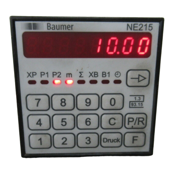
Page 4: Getting To Know The Counter
Getting to know the counter NE215 Getting to know the counter The counter comprises the following: – Presetting the counter with 2 preset value, (preliminary testing by PTB) – Secondary counter with preset value and multiplier, – Totalizing counter, (preliminary testing by PTB) –... -
Page 5: Block Diagram
Getting to know the counter NE215 Example for print Main counter systems: (PTB-approved) 1 up/down preset counter with totalizer. Batch counter systems: 1 preset counter, adding. A key provided at the counter enables switching the display to the respective counters of the main respectively batch counting system. -
Page 6: Supply Voltage Connection
Counter connect NE215 Counter connect This chapter will explain how the contacts are assigned. Under chapters 3.1 to 3.5 you will find actual tips and technical data for the various connections. The electrical inputs and outputs are assigned to two 12-pole plug-in screw terminals, coded to prevent reversed polarity. - Page 7 Counter connect NE215 Connecting the power supply For power supply following voltage ranges are available: AC 115/230 VAC (50/60 Hz) DC 24 VDC ±10% Voltage supply Recommended external fuse 115/230 VAC M 125 mA 24 VDC M 400 mA ➜ Assign voltage supply to terminals 2 and 3 according to diagramm.
-
Page 8: Assignment Of Signal Inputs
Counter connect NE215 3.3 Assignment the signal inputs Terminals 12 to 17 are AC optocoupler inputs. Terminals 12 (track A) and 13 (track B) are pulse inputs for the main counter (XP) counting function. Terminal 14 is an external reset input for the main counter. - Page 9 Counter connect NE215 3.4 Connecting the encoder supply Connect the encoder supply at terminals 19 and 20. Do not use the encoder supply to supply non-earthed inductive or capacitive loads. The encoder power supply is not short-circuit proof. Terminal Voltage Max.
-
Page 10: Executing The Test Routine
Counter connecting and operating NE215 3.6 Executing the test routine The test routine is described below. Druck To start test Press the key simultaneously. Switch the counter on. All the display segments will be displayes automatically in sequence and are therby tested for functional capability. - Page 11 Operating mode NE215 Operating mode The operation and use of the counter are described in this section. As soon as the power supply has been switched on, the counter is automatically set to the operating mode. Operating mode In the operating mode: –...
- Page 12 Operating mode NE215 If other values are changed, the value at witch the operating level was left can be re-displayed with the key after the programming mode has been left. Other changes Press the key. Read preset value P2 To change Press the key.
- Page 13 Operating mode NE215 Secondary counter preset status To read Press the key. Read the secondary preset value. To change Press the LED B1 flashes. Press the key. Preset value of the batch counter is being deleted. Input the new secondary counter preset value via the numerical keypad.
-
Page 14: Programming Mode
Programming mode NE215 Programming mode This section describes the procedure for programming the counter. Programming mode Operating parameters are set in the programming mode, which is subdivided into four programming segments. Programming segment 1 In the first programming segment, all the operating parameters can be accessed and changed. - Page 15 Programming mode NE215 Druck Key for printing Function in the operating mode The simultaneous operation of the Key for printing an the starts the test routine; the power supply must be switched on at the same time. Function in operating and Printout release of the main counter.
- Page 16 NE215 Programming mode Programming segment 1 Information on the displays and changing individual values is also given in Part 4. Press the key again. The operating parameters are now called up. The respective LED flashes. To changing operating parameters Input the new values via the numerical keypad.
- Page 17 Programming mode NE215 Programming segment 2 In the second programming segment, the message STAT appears in the display, signifying status selection. appears in the display. The LED for the corresponding operating parameter flashes. Significance of status numbers 0 Full access for operator (read and alter parameters).
-
Page 18: Operating Modes
Programming mode NE215 Programming segment 3 Programming segment 3 begins with programming line 21. 14 programming lines are displayed in sequence in these segments. Default settings are always printed with * . Operating modes Line 21 * Step preset P1 Self-adjusting preset... - Page 19 Programming mode NE215 Line 36 Secondary counter functions XB * External Internal Tachometer Line 37 Pulses per unit of measurement, as tachometer 1.00 * 1,00 0,01 - 9999.99 Line 38 Input of time measurement in seconds (s) * Time base 1 s...
- Page 20 Programming mode NE215 Programming field 4 Line 43 Baud rate 0 * 4800 baud 2400 baud 1200 baud 600 baud Line 44 Parity 0 * Even parity Odd parity No parity Line 45 Address 1-99 Line 46 Stop bits 0 * 1 Stop bit...
-
Page 21: Counting Modes For Main And Totalizing Counter
Programming mode NE215 5.2 Counting modes for the main and totalizing counter Up/down counting with two counting signals, phase-offset by Track A 90 degrees Track B The counting direction is automatically identified from the leading/ lagging 90 phase offset. The internal phase discriminator performs the necessary evaluation. -
Page 22: Technical Data
Technical data NE215 Technical data Display 7-segment-LED display 8-digit, red with minus sign Digit height 7 ,6 mm Power supply As per purchase order Power consumption 7 VA, 6 W Encoder power supply 12...26 VDC, max. 80 mA Optocoupler inputs NPN, PNP Max. -
Page 23: Dimensions And Cutout Size
Technical data NE215 6.1 Dimensions and cutout size Sealing screw Packing 75 min. Cutout 68 + 0.7 x 68 + 0.7 mm 68 +0,7 6.2 Default settings The following parameters are programmed into the counter by the factory prior to delivery:... -
Page 24: Open Interface Description
Open interface description NE215 Open interface description General information The open interface is of the RS485 type. It is possible to send the commands documented in the „Description of the Open Interface“ for remote control to the counter. The interface allows to call up data and to change the programming of parameters not relevant for the values to be calibrated. - Page 25 Open interface description NE215 Important The blanks between the particular characters of the commands only serve the purpose of better legibility. The input at the PC must be effected without blanks. Control characters (less than 20Hex) are set in „pointed“ brackets. If a false protocol has been sent by the PC, the counter will return an error message.
- Page 26 Open interface description NE215 The protocol: <STX> Address line P [VZ] data <ETX> [<CR>] can be used for each line. The answer of the counter that is returned after every programming step is the same as for the readout of the line.
- Page 27 „I“ (for identification) and the selection parameter „ T“ (Type and programming number) or „D“ (date and version) for the different identification data. Readout device type and programming number: Address=35, Type=NE215, Programming number=03 Command: <STX>35IT<ETX> Answer: <STX>35NE215 03<ETX><CR>...
- Page 28 NE215 Open interface description Output to the printer The command parameter „D“ allows the initiation of the output of the lines 01, 02, 03 and 05 to the printer. 7.6.1 Appearance of the printout The printout comprises - date and time that need to be sent along by the PC upon a print...
- Page 29 NE215 Open interface description Answer: <STX>3501D<CAN>4<ETX><CR> 7.6.4 Printout of the lines 02, 03: preselections P1 and P2 As these are not length measurements that need to be calibrated, the value of the preselections P1 and P2 is not printed with the sign *, and it is also not necessary that the PC sends Date/Time along.
- Page 30 Open interface description NE215 General structure of the error messages: <STX> Address Line Status <CAN> Error number <ETX> <CR> Example: Address=35, Line=09 (invalid line), Error number=2 <STX>3509R<CAN>2<ETX><CR> The two positions „Line“ and „Status“ will not occur with the special commands.
- Page 31 Open interface description NE215 Operating Plan Line Display Short description Preselection counter XP Preselection 1 Preselection 2 Not applicable Totalizer Batch counter Preselection batch counter Time meter Separating line Status of preselection counter XP Status of preselection 1 Status of preselection 2...
- Page 32 Open interface description NE215 7.10 Programming plan Lines in italic* = Factory setting Line 11-18 Status for line 11-18 0 * Parameter can be changed Clearing and/or input disabled Parameter is skipped Line 21 Operating mode principal count system 0 * Progressive preselections...
- Page 33 Open interface description NE215 Line 36 Function of batch counter 0 * external internal Tachometer Line 37 Impulses per unit at tachometer 00.00 Minimum value 1.00 * Default value 9999.99 Maximum value Line 38 Time basis for tachometer function 0 * 1 secound...
-
Page 34: Supplementary Operation Manual
Supplement NE215 8. Supplementary operation manual for open and closed interface (February 1994, Erg. 31.8.1994) The addendum describes the interfaces and documents the modifications of the Operating Instructions for the Counter regarding the additional open interface. Corresponding to the 1st. addendum to file number: 1.62-3251.11 IVO-040293 dated 16.03.1995. - Page 35 Supplement NE215 - the number of stop bit The contacts 21(-T,R) and 22(+T,R) are assigned to the open RS485-type interface. 9. Supplement to the scaling factor manual (May 1999) This supplementary manual is describing the modification of the counter’s operation manual regarding application of the scaling factor and the alibi printer SP 298 of the company Star.
-
Page 36: Scaling Factor
NE215 Supplement to the operation manual with scaling factor 9.2 Modifications in Chapter 3: „Counter connection“ New pin assignment for pin 15: scaling on. 9.2.1Modifications in Chapter 3.3: „Assignment of signal inputs“ Pin 15 is for activating the setting of the scaling factor (line 22 programming level). -
Page 37: Suitable Encoder
NE215 Suitable encoder PTB-version 10. Suitable encoder Technical Data Model Incremental Encoder RPM value 10.000 min Supply Voltage 10...30 VDC, with reverse voltage protection Input signals Push-pull, outp., short-circuit-protect. Signal output Kanal A, B, N Resolution Up to 500 Impuls Current consumption Max. - Page 38 Suitable encoder PTB-version NE215 Pin assignment Assignment Cable color blue beige green brown black Output signals Signals with clockwise sense or rotation when looking at the flange. Track A Track B Zero pulse Push-pull output (10...30 VDC) Level High > UB -3 V...
- Page 39 Models/order designation Part number NE215. Display 5 In cm, 9999.99 50 pulses/rev. w/o interface/RS232 6 In mm, 999.999 500 pulses/rev. w/o interface/RS232 7 In cm, 9999.99 50 pulses/rev. at RS232/RS485 8 In mm, 999.999 500 pulses/rev. at RS232/RS485 Voltage supply...
Need help?
Do you have a question about the NE215 and is the answer not in the manual?
Questions and answers