Table of Contents
Advertisement
Advertisement
Table of Contents

Related Manuals for DSC RF5501-433


Summary of Contents for DSC RF5501-433
- Page 1 WARNING: Please refer to the System Installation Manual for information on limitations regarding product use and function and information on the limitations as to liability of the manufacturer. Installation Manual RF55O1-433 version 5.O DLS2002 and higher firealarmresources.com...
- Page 2 WARNING Please Read Carefully Note to Installers Every fire is different in the amount of smoke produced and the rate This warning contains vital information. As the only individual in of burning. Smoke detectors cannot sense all types of fires equally contact with system users, it is your responsibility to bring each item well.
-
Page 3: Table Of Contents
Enroll Wireless Devices Using Zones ..............9 A Note About Electronic Serial Numbers ............... 10 Enroll Wireless Devices Using Zones ..............10 RF5501-433 PGM Outputs ..................11 Deleting Wireless Devices ..................11 Section 4: Other Programming Program Zones and Partitions ................12 Enable Receiver Supervision .................. -
Page 4: Introduction
• The wiring used in this circuit connection shall be insulated with PVC, TFE, PTFE, FEP neoprene or polymide. • Compatibility: The RF5501-433 can be connected to the following panels: PC5010, PC5015, PC5020, PC5008, PC1555/1565, PC580/585 • Connects to control panel via 4-wire Keybus •... -
Page 5: Section 1: Installation
Red Blk Yel Grn P1 P2/Z 3. You can connect a device, such as a door contact, to the “Z” terminal of the RF5501-433. This eliminates the need to run wires back to the control panel for the device. To connect the zone, run one wire from the device to the Z terminal and the other wire from the device to the B (black) terminal. -
Page 6: Applying Power
There are eight available slots for keypads. RF5501-433 keypads are always assigned to slot 1 by default. You will need to assign each keypad to its own slot (1 to 8). -
Page 7: Downloading
1. Enter [✱][8][Installer’s Code] 2. Enter [903] to display all modules. On the RF5501-433 keypad, 1 1 1 1 1 and 1 1 1 1 1 7 7 7 7 7 will scroll on the keypad to indicate that the RF5501-433 is present on the system. 1 1 1 1 1 designates the keypad section, and 17 17 is used to show the receiver section is also supervised. -
Page 8: Section 2: Keypad Programming
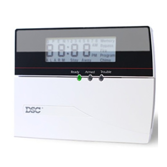
2.3 Clock Options The RF5501-433 will display the current time after 30 seconds of no key presses. To set the correct time and date for the system, please refer to your system’s Instruction Manual . -
Page 9: Alarms Displayed While Armed Option
There are two parts to the RF5501-433 door chime programming: • Program if the RF5501-433 will chime when zones are opened and/or closed. • Program the type of sound the RF5501-433 will make when an individual zone is opened or closed. -
Page 10: Low Temperature Alert
Door Chime Sounds You can program the RF5501-433 keypad to make different door chime sounds for individual zones, or groups of zones. Each RF5501-433 keypad can make any of four door chime sounds for each zone that triggers the door chime: •... -
Page 11: Section 3: Receiver Programming
(using [✱][5] access code programming) for this feature to work correctly. NOTE: Program these access codes on the system after you have connected the RF5501-433 to the Keybus (see section 2.4). Refer to your system Installation Manual for information on access code programming. -
Page 12: A Note About Electronic Serial Numbers
The (P)WLS909-433 and (P)WLS919-433 keys have both a 5-digit and a 6-digit serial number printed on them. When connecting the RF5501-433 to a PC5010 v1.x or P-832 v1.x panel, enter 5-digit serial numbers only. When connecting the RF5501-433 to a PC5020, P-8+, PC5015 v2.x and higher, P832DL v2.x and higher, PC5010 v2.0 and higher, P832 v2.0 and higher,... -
Page 13: Rf5501-433 Pgm Outputs
5. Record your programming choices in the worksheets in the back of the manual. 6. To exit press [#]. 3.5 RF5501-433 PGM Outputs The RF5501-433 has two on-board open collector PGM outputs. Each of these can be individually programmed to: 1. Follow main panel PGM outputs 1 to 14. -
Page 14: Section 4: Other Programming
The system will generate a General System Supervisory trouble if the module is removed from the Keybus. If you need to remove the PC5132 portion of the RF5501-433 module from an existing system, you will have to disable supervision of the PC5132. -
Page 15: Enable Supervision Of Wireless Zones
If the PC5132 portion of the RF5501-433 module does not show on the keypad, one of the following conditions may be present: • the module is not connected properly to the Keybus • there is a problem with the Keybus wiring run •... -
Page 16: Receiver Software Default
[804]. NOTE: Performing this procedure will not change any programming sections except [804]. Resetting the control panel to factory default settings will not return the RF5501-433 to factory default settings. -
Page 17: Section 5: Testing & Mounting
RF5501-433 to a better location. 7. To test another device, press [#] once, then repeat steps 4 - 6. Continue to test the devices until both the RF5501-433 and the devices are in good locations. 8. To exit installer programming, press [#] twice. -
Page 18: Test Wls909 And Wls919 Reception
RF5501-433 receiver. Moving the RF5501-433 higher will usually improve the reception. If you move the RF5501-433, repeat the tests described in sections 5.1 and 5.2 on all the wireless devices. Continue to test the devices until you have found... -
Page 19: Section 6: Additional Notes
Installation Manual . The following trouble conditions apply to the RF5501-433 and/or any enrolled devices. General System Tamper - This trouble is generated when the RF5501-433 plastic cover is removed and/or if there is a jamming condition present. -
Page 20: Section 7: Troubleshooting
• Verify that you are testing the correct zone • Verify that the correct ESN was entered when the device was enrolled • Verify that the device is in range of the RF5501-433. Try testing the device in the same room as the receiver. -
Page 21: Section 8: Programming Worksheets
I _ _ ______I _ _______I I _ _______I _ _______I I _ _ ______I _ _______I I _ _ ______I _ _______I I _ _ ______I _ _______I [6] RF5501-433 Keypad Options Default Option On Local Clock Display Enabled Display Disabled... - Page 22 P R O G R A M M I N G W O R K S H E E T S [*] Door Chime Sound Programming 1. Enter [*][8][Installer’s code][*] 2. Enter 2-digit zone number [01] - [32], then select door chime sound option [1] - [4]. Repeat for each zone that is to sound a chime.
- Page 23 P R O G R A M M I N G W O R K S H E E T S Zone Location 4 Beeps “Bing-bing”“Ding-dong”Alarm tone (default) [33] I________I I________I I________I I________I I__________________________________________________________________I [34] I________I I________I I________I I________I I _ _________________________________________________________________I [35] I________I I________I...
- Page 24 P R O G R A M M I N G W O R K S H E E T S [804] Wireless Expansion Programming (PC5132 portion) • 6-digit entry is required. See Section 3.1 “A note on Electronic Serial Numbers” for details on programming 6-digit serial numbers.
- Page 25 [✱ [✱ [✱ [✱ [✱ [✱ a i l [✱ [✱ t i x Sensor Reset can be used when the RF5501-433 is connected to the PC5010. Command outputs are not available for PC5010 software v1.x. firealarmresources.com...
- Page 26 P R O G R A M M I N G W O R K S H E E T S Wireless Key Options Partition 1 Wireless Key Options [61] Function Key 1 Function Key 3 l _ ___ l _ ___ l l _ ___ l _ ___ l Function Key 2 Function Key 4...
- Page 27 Default 01 Default 01 Default 01 Default 01 Default 01 PGM1 Output Option l _ _______ l ________ l RF5501-433 Output Options [71] RF5501 PGM2 Output Option Default 02 Default 02 Default 02 Default 02 Default 02 PGM2 Output Option...
- Page 28 P R O G R A M M I N G W O R K S H E E T S Zone Device Supervision Options (1-8) Zone Device Supervision Options (1-8) [82] Zone Device Supervision Options (1-8) Zone Device Supervision Options (1-8) Zone Device Supervision Options (1-8) Default = ON Option ON...
- Page 29 P R O G R A M M I N G W O R K S H E E T S [85] Zone Device Supervision Options (25-32) Default = ON Option ON Option OFF Option 1 Zone 25 Supervision enabled Disabled l _ _______ l Option 2...
-
Page 30: Appendix A: Guidelines For Locating Smoke Detectors
Guidelines for Locating Smoke Detectors Experience has shown that all hostile fires in family living units generate smoke to a greater or lesser extent. Experiments using typical fires in family living units indicate that detectable quantities of smoke precede detectable levels of heat in most cases. In existing homes, NFPA Standard 72 requires that a smoke detector be installed outside each sleeping area and on each additional story of the family unit. - Page 31 In such cases, DSC can replace or equipment, cost of capital, cost of substitute or replace- credit at its option.
- Page 32 The term "IC:" before the radio certification number only signifies that Industry Canada technical specifications were met. Direct all comments con- ©2002 Digital Security Controls Ltd. cerning this publication to Toronto, Canada • www.dsc.com pubs@dscltd.com Technical Support 1-800-387-3630 Printed in Canada 29034573 R001...
Need help?
Do you have a question about the RF5501-433 and is the answer not in the manual?
Questions and answers