Siemens RUGGEDCOM RS8000H Installation Manual
Hide thumbs
Also See for RUGGEDCOM RS8000H:
- Installation manual (40 pages) ,
- Installation manual (40 pages)

Related Manuals for Siemens RUGGEDCOM RS8000H


Summary of Contents for Siemens RUGGEDCOM RS8000H
- Page 1 Preface Introduction Installing the Device RUGGEDCOM RS8000H Communication Ports Technical Specifications Dimension Drawings Installation Guide Certification 11/2015 RC1022-EN-03...
- Page 2 Warranty Siemens warrants this product for a period of five (5) years from the date of purchase, conditional upon the return to factory for maintenance during the warranty term. This product contains no user-serviceable parts. Attempted service by unauthorized personnel shall render all warranties null and void.
- Page 3 RUGGEDCOM RS8000H Installation Guide...
- Page 4 RUGGEDCOM RS8000H Installation Guide...
-
Page 5: Table Of Contents
RUGGEDCOM RS8000H Installation Guide Table of Contents Table of Contents Preface ....................... Alerts ..............................vii Related Documents ..........................vii Accessing Documentation ........................vii Training ............................viii Customer Support ..........................viii Chapter 1 Introduction ......................1.1 Feature Highlights ........................1 1.2 Ports, Controls and Indicator LEDs ....................2 Chapter 2 Installing the Device .................... - Page 6 RUGGEDCOM RS8000H Table of Contents Installation Guide 4.4 Fiber Optic Ethernet Port Specifications ..................16 4.5 Operating Environment ....................... 16 4.6 Mechanical Specifications ......................17 Chapter 5 Dimension Drawings ..................Chapter 6 Certification ......................6.1 Agency Approvals ........................21 6.2 FCC Compliance ........................21 6.3 Industry Canada Compliance ......................
-
Page 7: Preface
Installation Guide Preface Preface This guide describes the RUGGEDCOM RS8000H. It describes the major features of the device, installation, commissioning and important technical specifications. It is intended for use by network technical support personnel who are responsible for the installation, commissioning and maintenance of the device. -
Page 8: Training
Siemens sales representative. Customer Support Customer support is available 24 hours, 7 days a week for all Siemens customers. For technical support or general information, contact Siemens Customer Support through any of the following methods: Online Visit http://www.siemens.com/automation/support-request... -
Page 9: Introduction
Installation Guide Introduction Introduction The RUGGEDCOM RS8000H provides substation hardened, fully managed, Ethernet switches specifically designed to operate reliably in electrically and environmentally harsh environments. The RS8000H model provides IEEE 1613 Class 2 error-free communications performance under EMI stress. An operating temperature range of -40 to 85 °C (-40 to 185 °F) allows the RS8000H to be placed in almost any location. -
Page 10: Ports, Controls And Indicator Leds
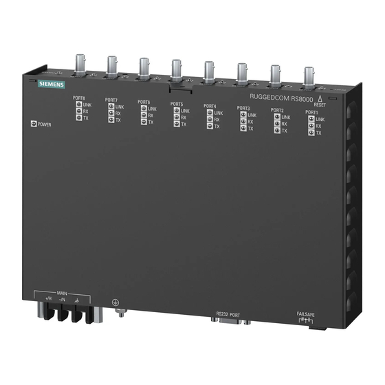
Chapter 1 RUGGEDCOM RS8000H Introduction Installation Guide • Enable/disable ports, MAC based port security • Port based network access control (802.1x) • VLAN (802.1Q) to segregate and secure network traffic • RADIUS centralized password management • SNMPv3 authentication and 56-bit encryption Management Tools •... - Page 11 RUGGEDCOM RS8000H Chapter 1 Installation Guide Introduction Figure 1: Front and Rear Panels 1. Power Indicator LED 2. Reset Button 3. Port Status Indicator LEDS 4. RS232 Serial Console Port (DB9) Power Indicator LED This LED indicates the status of the power supply.
- Page 12 RUGGEDCOM RS8000H Chapter 1 Installation Guide Introduction Ports, Controls and Indicator LEDs...
-
Page 13: Installing The Device
This product contains no user-serviceable parts. Attempted service by unauthorized personnel shall render all warranties null and void. Changes or modifications not expressly approved by Siemens Canada Ltd. could invalidate specifications, test results, and agency approvals, and void the user's authority to operate the equipment. -
Page 14: Mounting The Device On A Din Rail
Chapter 2 RUGGEDCOM RS8000H Installing the Device Installation Guide • Section 2.1.3, “Mounting the Device to a Panel” Section 2.1.1 Mounting the Device on a DIN Rail To mount the device to a standard 35 mm (1.4 in) DIN rail, do the following: Align the adapters with the DIN rails and slide the device into place. -
Page 15: Mounting The Device To A Panel
RUGGEDCOM RS8000H Chapter 2 Installation Guide Installing the Device Figure 3: Rack Mounting 1. Rack Mount Adapter 2. Screw Insert the rack mount adapter and device assembly into the rack. NOTE Since heat within the device is channelled to the enclosure, it is recommended that 1 rack-unit of space, or 44 mm (1.75 in), be kept empty above the device. -
Page 16: Connecting Power
Chapter 2 RUGGEDCOM RS8000H Installing the Device Installation Guide Figure 4: Panel Mounting 1. Screw 2. Panel/DIN Rail Adaptor Install the supplied screws to secure the adapters to the panel. Section 2.2 Connecting Power The RS8000H supports a single integrated high AC/DC or low DC power supply IMPORTANT! •... -
Page 17: Connecting Ac Power
RUGGEDCOM RS8000H Chapter 2 Installation Guide Installing the Device • Section 2.2.1, “Connecting AC Power” • Section 2.2.2, “Connecting DC Power” Section 2.2.1 Connecting AC Power To connect a high AC power supply to the device, do the following: CAUTION! Electrical hazard –... -
Page 18: Connecting The Failsafe Alarm Relay
Chapter 2 RUGGEDCOM RS8000H Installing the Device Installation Guide This cable connects transient suppression circuitry to chassis ground and must be removed in order to avoid damage to transient suppression circuitry during testing. Connect the positive wire from the power source to the positive/hot (+/L) terminal on the terminal block. -
Page 19: Grounding The Device
RUGGEDCOM RS8000H Chapter 2 Installation Guide Installing the Device Figure 7: Failsafe Alarm Relay Wiring 1. Normally Closed 2. Common 3. Normally Open Section 2.4 Grounding the Device The RS8000H chassis ground terminal uses a #6-32 screw. It is recommended to terminate the ground connection with a #6 ring lug and torque it to 1.7 N·m (15 lbf·in). -
Page 20: Cabling Recommendations
Section 2.6 Cabling Recommendations Siemens does not recommend the use of copper cabling of any length for critical, real-time substation automation applications. All copper Ethernet ports on RUGGEDCOM products include transient suppression circuitry to protect against damage from electrical transients and conform with IEC 61850-3 and IEEE 1613 Class 1 standards. -
Page 21: Communication Ports
RUGGEDCOM RS8000H Chapter 3 Installation Guide Communication Ports Communication Ports The RS8000H can be equipped with various types of communication ports to enhance its abilities and performance. To determine which ports are equipped on the device, refer to the factory data file available through ROS . -
Page 22: Fiber Optic Ethernet Ports
Chapter 3 RUGGEDCOM RS8000H Communication Ports Installation Guide Name Description Receive Data+ Receive Data- Transmit Data+ Reserved (Do Not Connect) Figure 11: RJ45 Ethernet Port Pin Configuration Reserved (Do Not Connect) Transmit Data- Reserved (Do Not Connect) Reserved (Do Not Connect) -
Page 23: Technical Specifications
RUGGEDCOM RS8000H Chapter 4 Installation Guide Technical Specifications Technical Specifications The following sections provide important technical specifications related to the device and available modules: • Section 4.1, “Power Supply Specifications” • Section 4.2, “Failsafe Relay Specifications” • Section 4.3, “Copper Ethernet Port Specifications”... -
Page 24: Copper Ethernet Port Specifications
Chapter 4 RUGGEDCOM RS8000H Technical Specifications Installation Guide Section 4.3 Copper Ethernet Port Specifications The following details the specifications for copper Ethernet ports that can be ordered with the RS8000H. Speed Connector Duplex Cable Type Wiring Standard Maximum Distance Isolation... -
Page 25: Mechanical Specifications
RUGGEDCOM RS8000H Chapter 4 Installation Guide Technical Specifications Section 4.6 Mechanical Specifications Parameter Value Dimensions Refer to Chapter 5, Dimension Drawings Weight 2.25 kg (5 lbs) Ingress Protection IP40 (1 mm or 0.04 in objects) Enclosure 18 AWG Galvanized Steel... - Page 26 RUGGEDCOM RS8000H Chapter 4 Installation Guide Technical Specifications Mechanical Specifications...
-
Page 27: Dimension Drawings
RUGGEDCOM RS8000H Chapter 5 Installation Guide Dimension Drawings Dimension Drawings NOTE All dimensions are in millimeters, unless otherwise stated. 248.9 Figure 14: Overall Dimensions... - Page 28 Chapter 5 RUGGEDCOM RS8000H Dimension Drawings Installation Guide 479.4 464.5 Figure 15: Rack Mount Dimensions 274.3 264.2 Figure 16: Panel and Din Rail Mount Dimensions...
-
Page 29: Certification
RUGGEDCOM RS8000H Chapter 6 Installation Guide Certification Certification The RS8000H device has been thoroughly tested to guarantee its conformance with recognized standards and has received approval from recognized regulatory agencies. • Section 6.1, “Agency Approvals” • Section 6.2, “FCC Compliance”... -
Page 30: Emi And Environmental Type Tests
Chapter 6 RUGGEDCOM RS8000H Certification Installation Guide Section 6.4 EMI and Environmental Type Tests The RS8000H has passed the following EMI and environmental tests. IEC 61850-3 Type Tests Test Description Test Levels Severity Levels IEC 61000-4-2 Enclosure +/- 8 kV... - Page 31 RUGGEDCOM RS8000H Chapter 6 Installation Guide Certification Test Description Test Levels Severity Levels IEC 60255-5 Dielectric Strength Signal ports 2 kVAC (Fail-Safe Relay output) DC Power ports 1.5 kVDC AC Power ports 2 kVDC HV Impulse Signal ports 5 kV (Fail-Safe Relay Output)
- Page 32 Chapter 6 RUGGEDCOM RS8000H Certification Installation Guide Test Description Test Levels Severity Levels IEC 60068-2-30 Humidity (Damp Test Db 95% (non-condensing), Heat, Cyclic) 55 °C (131 °F), 6 cycles IEC 60255-21-1 Vibration 2 g @ 10-150 Hz Class 2 IEC 60255-21-2...
Need help?
Do you have a question about the RUGGEDCOM RS8000H and is the answer not in the manual?
Questions and answers