
Related Manuals for Mean Well HEP-2300 Series


Summary of Contents for Mean Well HEP-2300 Series
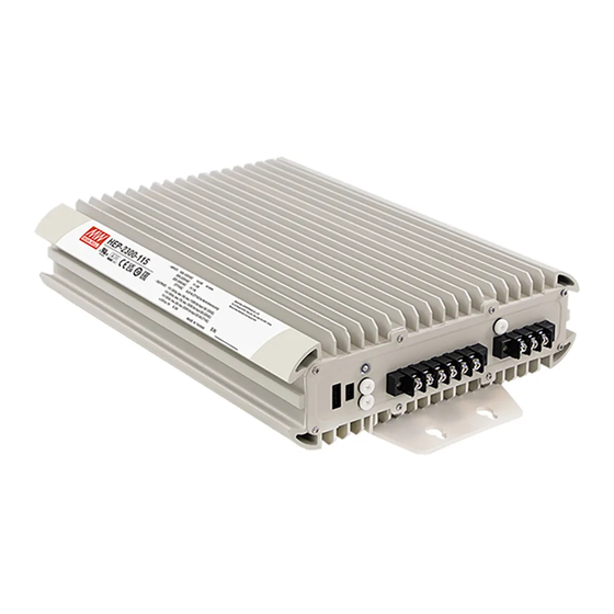
- Page 1 HEP-2300 Series Installation manual Security Industrial Network Automate Telecom Switching Power Supply for Harsh Environment High efficiency Filling with heat-conducted glue Conduction cooling...
- Page 2 TUV EN62368-1 UL62368-1 and design refers to EN61558-1 and EN60335-1. HEP-2300 series serves as a high performance power supply solution for various industrial and telecom applications. In addition, the 55V model also supports charge function for lead-acid and lithium ion...
-
Page 3: Table Of Contents
Contents 1.Safety Guidelines Remote Control DC-OK Signal 2.Introduction Auxiliary Output 2 1 . Model Encoding 5.10 Charging 55V only 2.2 Features 5 1 . 1 Factory Resetting 2 3 Specification 2 4 Derating curve 6.Communication Protocol 2 5 . Mechanical specification PMBus Communication 2 6 Output Type Interface... -
Page 4: Safety Guidelines
Modbus-RTU/RS-485 By request Risque de brûlure, la surface devient chaude pendant Note: 1.MEAN WELL can provide complete cable modification services. Please l'opération. Si un entretien est requis, contact sales representatives for details. veuillez éteindre l'appareil pendant au moins 30 minutes 2.Charger function by programmer or PMBus/CANBus/MODBus setting... -
Page 5: Features
Features Specification HEP-2300-55 series-Switching Power Supply Various Output voltage: 55V 115V 230V 380VDC MODEL HEP-2300-55 High efficiency up to 95.5% and active PFC function DC VOLTAGE (factory default) 55V Fanless design, cooling by free air convection CURRENT (factory default) 41.8A Aluminum case and filling with heat-conducted glue RATED CURRENT (max.) POWER (factory default) - Page 6 HEP-2300-55 series- HEP-2300-115/230/380 series-Switching Power Supply Charger MODEL HEP-2300-115 HEP-2300-230 HEP-2300-380 MODEL HEP-2300-55 DC VOLTAGE (factory default) 115V 230V 380V BOOST CHARGE VOLTAGE Vboost 57.6V CURRENT (factory default) 6.05A FLOAT CHARGE VOLTAGE Vfloat 55.2V RATED CURRENT (max.) 10.6A 6.9A RECOMMENDED BATTERY OUTPUT 120 ~ 400AH CAPACITY(AMP HOURS)
- Page 7 2. Ripple & noise are measured at 20MHz of bandwidth by using a 12" twisted pair-wire terminated with a 0.1uf & 47uf parallel capacitor. 3. This is Mean Well's suggested range. Please consult your battery manufacturer for their suggestions about maximum charging current limitation.
-
Page 8: 7 Accessory List
2.5 Mechanical specification 2. Output Ty 187.5 Terminal Wiring Harness connector( 55V only 2 7 Accessory List Optional equipment (Top View) MW’s Order No. Item Quantity DGG2BKT-001 259.5 M6 L=16*2 (For housing side) 2-M6 L=15 DGG2BKT-002 M6 L=16*2 (For pole side) 130.2 142.2 DGG2BKT-003... -
Page 9: Installation & Wiring
HEP-2300 can be installed onto a horizontal surface or a vertical wall. NOTE: 1. Vertical installation is only suitable for a firm surface with the ability to carry at least 1 KG. 2. Mounting orientation other than horizontal and vertical surfaces, please contact Mean Well. Horizontal mounting Vertical mounting 3.1.2 Pole Mounting 3.1.2.1... - Page 10 3.1.2.2 Side Mounting M6 L=16*2( Recommended torque 23 25kgf-cm)
-
Page 11: Wiring
3 2 . Wiring Choose the right and suitable cable size for connection between the HEP-2300 and the loads/batteries. Please refer to 3.3 DC cable size selection. Connect the DC positive polarity of the supply to the positive of the loads/batteries and connect the DC negative polarity of the supply to the negative of loads/batteries. -
Page 12: Dc Cable Size Selection
4. Panel and LED indicator 3 3 . DC Cable Size Selection Wire connections should be as short as possible and less than 1 meter is Terminal highly recommended. Make sure that suitable wires are chosen based on 4.1.1 Panel Description safety requirement and rating of current. - Page 13 4.1.2 Pin ssignment of CN11 4.1. Pin ssignment of CN 1 Remote Remote ON-OFF ON-OFF DC-OK DC-OK (Signal) (Signal) RTH+ RTH+ +12V-AUX +12V-AUX RTH- RTH- GND-AUX GND-AUX CANL CANH Pin No. Function Description Pin No. Function Description The unit can turn the output ON/OFF by dry contact between Remote Connection for output voltage programming.(Note) Remote ON/OFF and +12V-AUX.(Note)
-
Page 14: Wiring
Wiring 4. .2 Pin ssignment -Control Wire 4. .1 Panel Description LED ndicator: Indicate the status of the supply and load condition. SVR: For DC voltage setting. Address rotary switch For device addressing when communication interface is using. Hipot earthing screw: Remove the screw for high potential test. -
Page 15: Harness Connector Type
Harness connector type 55V only 4. . Pin ssignment -Control Wire 4. .1 Panel Description LED ndicator: Indicate the status of the supply and load condition. SVR: For DC voltage setting. Address rotary switch For device addressing when communication interface is using. Hipot earthing screw:... -
Page 16: Led Indicator
4. .2 Pin Assignment- Control Connector 4.3.3 Connector Mating AC Input Pin No, Assignment : ALTW CC-03PMMS-QC800P or equivalent Pin No. Assignment Mating connector AC L / CC-03BFFA-QL8APP or equivalent AC N 9 10 Max. 20A 11 12 DC Output 1,2 No. Assignmnet: ALTW CC-03PMFS-QC800P or equivalent Pin No. -
Page 17: Operation
Output 1 5.Operation HEP-2300-55H DC loads AC Input AC Input DC Output Function Difference 115V/230V/380V Max. 20A Max. 20A Terminal Wiring Harness Terminal Wiring Output 2 Charger function Battery Charger PV/PC PMBus Max. 20A CANBus Lithium iron/ Modbus RTU Output 3 Max. -
Page 18: Output Current Adjustment
5.5.2 PV (Output Voltage Programming) 5.6.1 PC(Output Current Programming 1.Connect output of the external DC source to PC and GND-signal, as 1.Connect output of the external DC source to PV and GND-signal, as shown in Figure 5-4. For detailed pin assignment of each type, shown in Figure 5-2. -
Page 19: Dc-Ok Signal
DC-OK Signal 2 stage charging Built-in DC output voltage detection circuit. In the initial stage of charging, the charger charges the battery ● Maximum output current 10mA. with the maximum current. After a period of time (depending on ● the battery capacity), the charging current decreases gradually. When the charging current drops to 10% of the rated current. - Page 20 SBP-001, the smart battery charging programmer developed by Stage 3 (float charging): MEAN WELL, can be used to set charging curves of the unit The charger is able to provide a float voltage after 2 stage charging in through editing software. SBP-001 provides functions such as order to keep the battery fully charged at all times.
-
Page 21: Factory Resetting
“ ” and then reboot the unit. Once (Mini USB) SBP-001 the digital communication dominates the unit, the analog signals MEAN WELL ENTERPRISES CO., LTD. Communication cable No. 28 Wuquan 3rd Rd., Wugu Dist., New Taipei City 24891, Taiwan 5V(Orange) 3.3V(Green) - Page 22 Table - Position Device address Command Command Transaction # of data Device No. Description of switch Code Name Type Bytes OPERATION R/W Byte Remote ON/OFF control ON/OFF function configuration ON_OFF_CONFIG Read Byte CAPABILITY Read Byte Capabilities of a PMBus device Define data format for output voltage VOUT_MODE R Byte...
- Page 23 Note: ◎Definition of Command B8h CHG_STATUS : ◎Definition of Command B4h CURVE_CONFIG : Bit7 Bit6 Bit5 Bit4 Bit3 Bit2 Bit1 Bit0 Bit7 Bit6 Bit5 Bit4 Bit3 Bit2 Bit1 Bit0 High byte FVTOF CVTOF CCTOF BTNC NTCER High byte FVTOE CVTOE CCTOE Low byte FULLM Low byte...
- Page 24 ◎Definition of Note: Command BFh SYSTEM_STATUS : NTCER When Temperature Compensation Short occurs, the output will Bit7 Bit6 Bit5 Bit4 Bit3 Bit2 Bit1 Bit0 shut down and the LED indicator will turn red. The charger will High byte automatically restart after the Temperature Compensation INITIAL_ Low byte EEPER...
-
Page 25: Can Bus Communication
Communication Timing ● For example: Min. request period (Controller to HEP-2300): 50mSec。 Vo_real (actual output voltage) = V x 2 , V is from READ_VOUT. Max. response time (HEP-2300 to Controller): 12.5mSec 。 If VOUT_MODE = 0x17, meaning N is -9. READ_VOUT is 0x3000 →... - Page 26 6.2.2 CANBus Command list Command Command Transaction # of data Description Code Name Type Bytes Command Command Transaction # of data Description Code Name Type Bytes CC charge timeout setting 0x00B5 CURVE_CC_ ON/OFF control of charging curve TIMEOUT 0x0000 OPERATION ON: 01h CV charge timeout setting 0x00B6...
- Page 27 ◎MFR_REVISION_B0B5 ( Bit 5 AC_FAIL:AC abnormal flag 0x0084 ) is the firmware revision (hexadecimal). A range of 0x00 (R00.0)~0xFE (R25.4) represents the firmware version 0=AC input range normal of an MCU; 0xFF represents no MCU existed. 1=AC input range abnormal EX: The supply has two MCUs, the firmware version of the MCU number Bit 6 OP_OFF:DC status...
- Page 28 Bit 2:3 TCS:Temperature Compensation Setting Bit 1 CCM:Constant Current Mode Status = disable 0=the charger NOT in constant current mode 01= -3 mV/℃/cell (default) 1=the charger in constant current mode 10= -4 mV/℃/cell Bit 2 CVM:Constant Voltage Mode Status 11= -5 mV/℃/cell 0=the charger NOT in constant voltage mode 1=the charger in constant voltage mode Bit 6...
- Page 29 byte0: Charge curve illustration: Bit 0:3 3 VOUT Factor:The factor of output voltage 3 Stage Charge 0x = Output voltage relevant commands not supported 0x4=0.001 Start boost 0x5=0.01 float 0x6=0.1 Charge 0x7=1.0 Voltage 100% 0x8=10 0x9=100 Constant Constant Charge Float Current Voltage Current...
- Page 30 ◎SYSTEM_STATUS (0x00C ) 1 byte2: : Bit :3 TEMPERATURE_1 Factor: The Factor of internal ambient temperature Bit7 Bit6 Bit5 Bit4 Bit3 Bit2 Bit1 Bit0 0x =internal ambient temperature relevant commands not supported INITIA- Low byte EEPER ADL_ON DC_OK LSTATE 0x4=0.001 0x5=0.01 Low byte: 0x6=0.1...
-
Page 31: 3 . Modbus Communication
◎SYSTEM_CONFIG (0x00C ) 2 : 6 3 . Modbus Communication Interface The device supports Modbus RTU with the master-salve principle. Bit7 Bit6 Bit5 Bit4 Bit3 Bit2 Bit1 Bit0 Users are able to read and write parameters of the device through Low byte OPERATION_INIT CAN_CTRL... - Page 32 6.3.2 Modbus Frame Encapsulation 6.3.5 Data Field and Command Lists Modbus RTU consists of Additional Address, Function Code, Data Data field provides additional information by the slave to complete the action specified by the function code( ) in a and Error Check. request.
- Page 33 Note: The conversion of setting and reading values is defined as Register Command Function # of data Description following: Actual value = Communication reading value Factor (F address Name code Bytes value). Among them, Factor needs to refer to the definition of Manufacture model name 0x0089~ MFR_MODEL_...
- Page 34 ◎MFR_ID_B0B5 (0x0080 -0x0082) is the first 6 codes of the Byte 0 Byte 1 Byte 2 Byte 3 Byte 4 Byte 5 manufacturer's name (ASCII); MFR_ID_B6B11(0x0083 -0x0085) is the 0xFE 0x69 0xFF 0xFF 0xFF 0xFF last 6 codes of the manufacturer's name (ASCII) EX: manufacturer's name is MEANWELL →...
- Page 35 Bit 6 STGS:2/3 Stage Charge Setting Bit 3 FVM:Float Mode Status = 3 stage charge(default, CURVE_CV and CURVE_FV) 0=the charger NOT in float mode 1= 2 stage charge (only CURVE_CV) 1=the charger in float mode Bit 7 CUVE:Charge Curve Function Enable High byte: 0=disabled power supply mode(default) Bit 2 NTCER:Temperature Compensation Status...
- Page 36 ◎SCALING_FACTOR (0x00C0): Charge curve illustration: Bit7~Bit0 2 Stage Charge byte4~5 Reserved Bit7 Bit6 Bit5 Bit4 Bit3 Bit2 Bit1 Bit0 Start boost byte3 Reserved IIN Factor Bit7 Bit6 Bit5 Bit4 Bit3 Bit2 Bit1 Bit0 Charge Voltage byte2 CURVE_TIMEOUT Factor TEMPERATURE_1 Factor 100% Bit7 Bit6...
- Page 37 byte1: Bit 4:7 CURVE_TIMEOUT Factor:The Factor of CC/CV/Float timeout Bit 0:3 VIN Factor:The Factor of AC input voltage 0x0=CURVE_TIMEOUT relevant commands not supported 0x0=AC input relevant commands not supported 0x4=0.001 0x4=0.001 0x5=0.01 0x5=0.01 0x6=0.1 0x6=0.1 0x7=1.0 0x7=1.0 0x8=10 0x8=10 0x9=100 0x9=100 0xA~0xF= Reserved 0xA~0xF= Reserved...
- Page 38 ◎SYSTEM_STATUS (0x00C3): 6.3.7 Communication Examples Bit7 Bit6 Bit5 Bit4 Bit3 Bit2 Bit1 Bit0 The following provides examples of request and response for each function code of the Modbus RTU. INITIA- Low byte EEPER ADL_ON DC_OK LSTATE 6.3.7.1 Read Holding Registers (FC=03) The request message specifies the starting register and quantity Low byte: of registers to be read.
-
Page 39: Value Range And Tolerance
Response: Command Name Display value range Tolerance Model 0x80 0x04 0x157C 0 0D03 0~57.6A ±0.53A 0x80: Slave ID 0 0x0 : Function code 4 (Read Analog Input Register) 115V 0~24A ±0.22A READ_IOUT 0x02: The number of data bytes to follow (2 bytes) (Note. -
Page 40: Protections And Trouble
7.Protections and Trouble Shooting Command Adjustable Tolerance Model Default Name range Protections CURVE_CC_ 7.1.1 Over Temperature Protection (OTP) and Alarm (T-Alarm only for TIMEOUT terminal type) 60~64800 ±5 CURVE_CV_ minute minute minute Built-in thermal detection circuit, once the internal temperature TIMEOUT exceeds a threshold value, the supply will shut down automatically. -
Page 41: Trouble Shooting
※ Battery cannot Battery aged or Replace a new battery MEAN WELL possesses the right to adjust the content of this manual. malfunction be fully charged Please refer to the latest version of manual on our website. https://www.meanwell.com... - Page 42 N o . 2 8 , W u q u a n 3 r d R d . , W u g u D i s t . , N e w Ta i p e i C i t y 2 4 8 , Ta i w a n...
Need help?
Do you have a question about the HEP-2300 Series and is the answer not in the manual?
Questions and answers