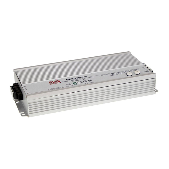
Mean Well HEP-1000 User Manual
Hide thumbs
Also See for HEP-1000:
- User manual (33 pages) ,
- Installation manual (9 pages) ,
- Installation manual (8 pages)
Table of Contents
Advertisement
Advertisement
Table of Contents

Summary of Contents for Mean Well HEP-1000
- Page 1 HEP-1000 User's Manual...
-
Page 2: Table Of Contents
3.8 Over-Temperature Protection and Alarm ........................ 3.9 DC OK Signal ......................3.10 Remote Control ......................3.11 Auxiliary Power ..............3.12 HEP-1000 PMBus Communication Interface 3.13 CAN Bus Communication Interface 4.Notes on Operation ..........................................4.1 Installation Method ........................4.2 Derating ........................ -
Page 3: Safety Guidelines
◎The input voltage range is 100-240Vac(50/60Hz), please do not feed in voltage that is over or less than 10% of that range. 1.Introduction Introduction HEP-1000 is equipped with modes of industrial power supply and charger, which can be selected by the communication interface. Feature Description ◎Built-in active PFC function. -
Page 4: Main Specification
Main Specification ◎Power supply MODEL HEP-1000-24 HEP-1000-48 HEP-1000-100 DC VOLTAGE 100V RATED CURRENT RATED POWER 1008W 1008W 1000W RIPPLE & NOISE (max.) 200mVp-p 250mVp-p 500mVp-p Note.2 By built-in potentiometer, SVR VOLTAGE ADJ. RANGE OUTPUT 24 ~ 30V 48 ~ 60V 100 ~ 125V ±1.0%... - Page 5 ◎Charger MODEL HEP-1000-24 HEP-1000-48 HEP-1000-100 BOOST CHARGE VOLTAGE V boost 28.8V 57.6V 115.2V FLOAT CHARGE VOLTAGE V float 27.6V 55.2V 110.4V RECOMMENDED BATTERY 120 ~ 350AH 60 ~ 175AH 30 ~ 85AH OUTPUT CAPACITY(AMP HOURS) (Note 2) BATTERY TYPE Open & Sealed Lead Acid OUTPUT CURRENT 17.5A...
-
Page 6: Mechanical Specification And Input/Output Terminals
Under this condition, the unit is still operating normally without entering Red (Flashing) OTP. (In the meantime, an alarm signal will be sent out through the PMBus/CAN bus interface) Abnormal status (Over temperature protection, charge timeout) CN71 Figure 2-2 HEP-1000 output panel... -
Page 7: Functions
After turning off the supply, a 10 second cool down period is recommended before turning on again. Output Power ◎Power supply mode HEP-1000-24 : 1008W (24V / 42A) HEP-1000-48 : 1008W (48V / 21A) HEP-1000-100 : 1000W (100V / 10A) ◎Charger mode HEP-1000-24 : 1008W (28.8V / 35A) -
Page 8: Output Voltage/Current Adjustment
3.5 Output Voltage/Current Adjustmen 3.5.1 Output voltage adjustment Output voltage can be trimmed by adjusting SVR (which can be found on the top case). Please utilize an insulated cross- head screwdriver to make an adjustment. Address Vo Adj. 3.5. Output Voltage Adjustment by an External 0-5Vdc Source (Output Voltage Programming) (1)Connect output of the external DC source to PV (PIN 1) and GND (PIN 3 or PIN 4) on CN71, as shown in Figure 3-1. -
Page 9: Short-Circuit And Over-Current Protection
Relationship between output current and external DC source is shown as below. Iout Non-Linear EXTERNAL VOLTAGE (DC) Note: The supply will trigger OLP to shut down itself if the output stays on constant current level condition for more than 5 seconds. Short Circuit Protection &... -
Page 10: Hep-1000 Pmbus Communication Interface
A0-A2 allow users to designate an address for the HEP-1000 unit, these two bits are defined through a rotary witch on the top case. There are up to 4 different addresses are available to be assigned. Please refer to Table 3-1 for the detailed setup advice. - Page 11 For detailed information, please refer to 3.13.6 PMBus Command List. 3.12 6 . PMBus Command List ◎The command list of the HEP-1000 is shown in Table 3-3. It is compliant with the standard protocol of PMBus Rev. 1.1. For detailed information, please refer to PMBus official website http://pmbus.org/specs.html). Table...
- Page 12 Command Command Transaction # of data Description Code Name Type Bytes Constant current setting value of charging curve CURVE_CC R/W Word (format: Linear, 24/48V:N= -4; 100V:N=-6) Constant voltage setting value of charging curve CURVE_CV R/W Word (format: Linear, 24/48V:N= -9; 100V:N=-7) Constant voltage setting value of charging curve CURVE_FV R/W Word...
- Page 13 ◎ : Definition of Command B8h CHG_STATUS Bit7 Bit6 Bit5 Bit4 Bit3 Bit2 Bit1 Bit0 High byte FVTOF CVTOF CCTOF BTNC NTCER Low byte FULLM Low byte Bit 0 FULLM : Fully Charged Mode Status 0=NOT fully charged 1=fully charged Bit 1 CCM : Constant Current Mode Status 0=the charger NOT in constant current mode...
- Page 14 Low byte Bit 0 PM_CTRL: PMBus Control Selection 0=Output voltage and current controlled by SVR/PV/PC (default) 1=Output voltage, current and remote ON/OFF controlled by PMBus (VOUT_TRIM, IOUT_FAULT_LIMIT, OPERATION) Bit 1: 2 OPERATION_INIT : OPERATION_INIT : Initial Operational Behavior 0b00=power on with 0x00: OFF 0b01=power on with 0x80: ON(default) 0b10=power on with the last setting 0b11=Not used...
-
Page 15: Canbus Communication Interface
2.When using PMBus to adjust output voltage, VOUT_COMMAND only can be used to display the voltage of the unit and cannot be written. It is VOUT_TRIM that provides voltage trimming function. Taking HEP-1000-24 as an example, to get a 12V output, please set value of VOUT_TRIM to -12V. -
Page 16: Notes On Operation
2.If you are unsure about max allowable charging current of your battery, please refer to the battery's technical specification or consult its manufacturer. Troubleshooting If you are unable to clarify the problem you are facing, please contact MEAN WELL or any of our distributors for repair service. Failure State Possible Cause... - Page 17 N o . 2 8 , W u q u a n 3 r d R d . , W u g u D i s t . , N e w Ta i p e i C i t y 2 4 8 , Ta i w a n...


Need help?
Do you have a question about the HEP-1000 and is the answer not in the manual?
Questions and answers