Table of Contents
Advertisement
Quick Links
Advertisement
Table of Contents

Related Manuals for Delta ShopMaster TS300


Summary of Contents for Delta ShopMaster TS300
- Page 1 10" Table Saw (Model TS300) PART NO. 908520 - 11-22-02 Copyright © 2002 Delta Machinery To learn more about DELTA MACHINERY ESPAÑOL: PÁGINA 29 visit our website at: www.deltamachinery.com. For Parts, Service, Warranty or other Assistance, 1-800-223-7278 ( 1-800-463-3582). please call...
-
Page 2: Safety Guidelines - Definitions
If you have any questions relative to a particular application, DO NOT use the machine until you have first contacted Delta to determine if it can or should be performed on the product. -
Page 3: Additional Safety Rules For Table Saws
17. REDUCE THE RISK OF UNINTENTIONAL STARTING. 21. NEVER LEAVE TOOL RUNNING UNATTENDED. Make sure switch is in “OFF” position before plugging in TURN POWER OFF. Don’t leave tool until it comes to a power cord. In the event of a power failure, move switch complete stop. -
Page 4: Power Connections
POWER CONNECTIONS A separate electrical circuit should be used for your machines. This circuit should not be less than #12 wire and should be protected with a 20 Amp time lag fuse. If an extension cord is used, use only 3-wire extension cords which have 3- prong grounding type plugs and matching receptacle which will accept the machine’s plug. -
Page 5: Extension Cords
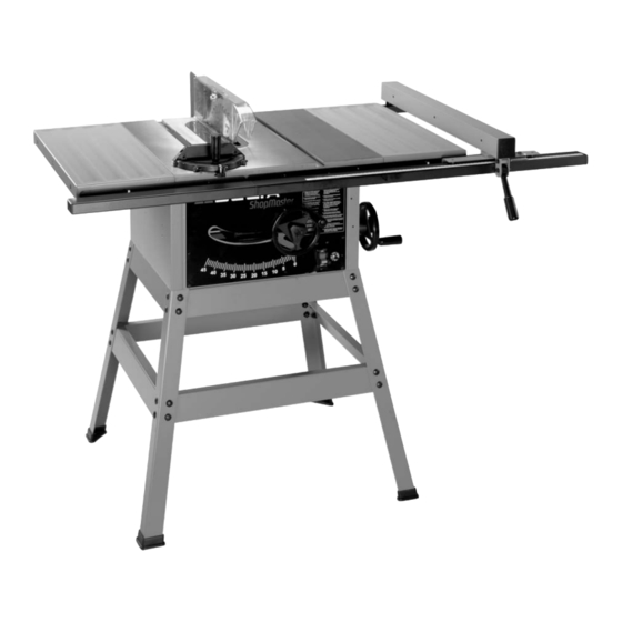
Delta ShopMaster Model TS300 is a 10" Table Saw designed to give high quality performance with depth of cut capacity up to 3-1/8" (79mm) at 90° and 2-1/8" (54mm) at 45° for clean cutting of standard stock sizes. Delta ShopMaster Model TS300 includes;... - Page 6 TABLE SAW PARTS Fig. 1 1. - Table Saw 9. - Right Front Rail 2. - Extension Wing (2) 10. - Left Front Rail 3. - Rip Fence 11. - Rail Extension Connector 4. - Miter Gage 12. - Right Rear Rail 5.
- Page 7 HARDWARE Fig. 2 For Blade Guard and Splitter Assembly For Fastening Saw to Stand 1. - Splitter Bracket 14. - M8x1.25x16mm Hex Head Screws (4) 2. - 5/8" Flat Washer (2) 15. - 3/8" Flat Washer (8) 3. - M12x1.75 Hex Nut (2) 16.
- Page 8 STAND PARTS Fig. 3 For Saw Stand 6. - M8x1.25x16mm Carriage Head Screw (32) 1. - Top Front and Rear Braces - 19" in length (2) 7. - M8x1.25 Hex Nut (32) 2. - Bottom Front and Rear Braces - 22-1/2" in length (2) 8.
- Page 9 ASSEMBLY FOR YOUR OWN SAFETY, DO NOT CONNECT THE MACHINE TO THE POWER SOURCE UNTIL THE MACHINE IS COMPLETELY ASSEMBLED AND YOU READ AND UNDERSTAND THE ENTIRE INSTRUCTION MANUAL. STAND Assemble stand as shown in Figs. 4 and 5 using parts shown in Fig.
-
Page 10: Extension Wings
BLADE RAISING AND TILTING HANDWHEELS 1. Assemble the blade raising handwheel (A) Fig. 7, to the blade raising shaft (B). Make sure the slots (C) in the hub of the handwheel are engaged with the roll pin (D) on the shaft. Fig. -
Page 11: Saw Blade
SAW BLADE DISCONNECT MACHINE FROM POWER SOURCE. 1. Remove the two table insert screws and remove the table insert (A) Fig. 11. IMPORTANT: Be careful not to lose two rubber washers (L) located under table insert (A). 2. Raise the saw blade arbor (B) Fig. 11, to its maximum height by turning the blade raising handwheel counterclockwise, remove the arbor nut (E) (turn Fig. -
Page 12: Guide Rails
GUIDE RAILS 1. Align the three slotted holes in the front right guide rail (A) Fig. 14, with two holes (B) in saw table and slotted hole (C) in extension wing. Insert a M6x1x20mm carriage head screw (D) Fig. 14, through the three holes in the front right guide rail, and the saw table. -
Page 13: Rip Fence
5. Align the holes in the longer section of rear guide rail (P) Fig. 18, with holes (A), (B), and (C) in the saw table. Place a M8.1 lockwasher then a M8.4 flat washer onto a M8x1.25x16mm hex head screw. Insert the screw through the hole (A) Fig. - Page 14 LEVELING AND ADJUSTING FRONT GUIDE RAIL DISCONNECT MACHINE FROM POWER SOURCE. 1. Raise the saw blade to its maximum height by turning the blade raising handwheel counterclockwise. 2. With handle (A) Fig. 22 in the raised position, place rip fence (B) on the saw table as shown. NOTE: Make certain rip fence (B) is engaged on rear guide rail (C).
- Page 15 BLADE GUARD AND SPLITTER ASSEMBLY DISCONNECT MACHINE FROM POWER SOURCE. 1. Thread a M12x1.75 hex nut (A) onto the splitter support rod (R) Fig. 26, as far as it will go. 2. Place a 5/8" flat washer (B) Fig. 26, onto the splitter support rod (R).
- Page 16 OPERATING CONTROLS AND ADJUSTMENTS STARTING AND STOPPING SAW The switch (A) is located on the front panel of the saw cabinet, as shown in Fig. 33. To turn the saw “ON”, move the switch up to the “ON” position. To turn the saw “OFF”, move the switch down to the “OFF”...
-
Page 17: Adjusting 90 And 45 Degree Positive Stops
ADJUSTING 90 AND 45 DEGREE POSITIVE STOPS Your saw is equipped with positive stops that will position the saw blade at 90 and 45 degrees to the table. To check and adjust the positive stops, proceed as follows: Fig. 36 Fig. -
Page 18: Rip Fence Operation
RIP FENCE OPERATION AND ADJUSTMENTS THE RIP FENCE MUST BE PROPERLY ALIGNED TO THE MITER GAGE SLOT IN ORDER TO PREVENT KICKBACK WHEN RIPPING. 1. To move the fence (A) Fig. 41, along the guide rails, lift up on the fence locking lever (B), slide the fence to the desired location on the guide rails and push down on the locking lever (B) to lock the fence in position. -
Page 19: Adjusting Table Insert
MITER GAGE OPERATION AND ADJUSTMENTS 1. Your miter gage is equipped with individually adjust- able index stops at 90 degrees and 45 degrees right and left. Adjustment to the index stops can be made by loosening lock nuts (A) Fig. 44, and tightening or loosening the three adjusting screws (B) against the stop link (C). -
Page 20: Maintenance
MAINTENANCE CHANGING THE BLADE DISCONNECT MACHINE FROM POWER SOURCE. USE ONLY 10" DIAMETER SAW BLADES RATED FOR 5500 RPM OR HIGHER WITH 5/8" ARBOR HOLES. 1. Raise saw blade to its maximum height and remove the table insert (A) Fig. 47A. NOTE: Be careful not to lose two rubber washers (E). - Page 21 The following information describes the safe and proper method for performing the most common sawing operations. THE USE OF ATTACHMENTS AND ACCESSORIES NOT RECOMMENDED BY DELTA MAY RESULT IN THE RISK OF INJURY.
-
Page 22: Using Accessory Moulding Cutterhead
RIPPING Ripping is the operation of making a lengthwise cut through a board, as shown in Fig. 49, and the rip fence (A) is used to position and guide the work. One edge of the work rides against the rip fence while the flat side of the board rests on the table. - Page 23 For certain cutting operations such as dadoing and moulding where you are not cutting completely through the workpiece, the blade guard and splitter assembly cannot be used. Always return and fasten the blade guard and splitter assembly to its proper operating position for normal thru-sawing operations.
-
Page 24: Using Accessory Dado Head
USING ACCESSORY DADO HEAD THE BLADE GUARD AND SPLITTER ASSEMBLY CANNOT BE USED WHEN DADOING OR MOULDING AND MUST BE REMOVED. Dadoing is cutting a rabbet or wide groove into the work. Most dado head sets are made up of two outside saws and four or five inside cutters, as shown in Fig. - Page 25 USING AUXILIARY WOOD FACING ON RIP FENCE It is necessary when performing special operations such as moulding to add wood facing (A) Fig. 60, to one or both sides of the rip fence, as shown. The wood facing is attached to the fence with wood screws, countersunk and assembled through the holes provided in the fence.
-
Page 26: Constructing A Push Stick
CONSTRUCTING A PUSH STICK When ripping work less than 4 inches wide, a push stick should be used to complete the feed and could easily be made from scrap material by following the pattern shown. -
Page 27: Parts, Service Or Warranty Assistance
Two Year Limited Warranty Delta will repair or replace, at its expense and at its option, any Delta machine, machine part, or machine accessory which in normal use has proven to be defective in workmanship or material, provided that the customer returns the product prepaid to a Delta factory service center or authorized service station with proof of purchase of the product within two years and provides Delta with reasonable opportunity to verify the alleged defect by inspection. - Page 28 NOTES...
- Page 29 Delta Distributor, Authorized · Service Center, or Porter-Cable Delta Factory Service Center. If you do not have access to any of these, call 800-223-7278 and you will · be directed to the nearest Porter-Cable Delta Factory Service Center. Las Estaciones de Servicio Autorizadas están ubicadas en muchas grandes ciudades.
Need help?
Do you have a question about the ShopMaster TS300 and is the answer not in the manual?
Questions and answers