Table of Contents
Advertisement
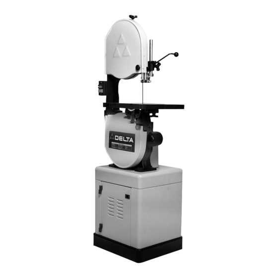
14" Band Saws
(Models 28-206, 28-276)
MODEL 28-206
PART NO. A05739 - 06-03-05
Copyright © 2005 Delta Machinery
To learn more about DELTA MACHINERY
ESPAÑOL: PÁGINA 27
visit our website at: www.deltamachinery.com.
For Parts, Service, Warranty or other Assistance,
1-800-223-7278 (
1-800-463-3582).
please call
In Canada call
Advertisement
Table of Contents

Related Manuals for Delta 28-206


Summary of Contents for Delta 28-206
- Page 1 14" Band Saws (Models 28-206, 28-276) MODEL 28-206 PART NO. A05739 - 06-03-05 Copyright © 2005 Delta Machinery To learn more about DELTA MACHINERY ESPAÑOL: PÁGINA 27 visit our website at: www.deltamachinery.com. For Parts, Service, Warranty or other Assistance, 1-800-223-7278 ( 1-800-463-3582).
-
Page 2: Table Of Contents
NOT be modified and/or used for any application other than for which it was designed. If you have any questions relative to its application DO NOT use the product until you have written Delta Machinery and we have advised you. -
Page 3: Safety Guidelines
SAFETY GUIDELINES - DEFINITIONS It is important for you to read and understand this manual. The information it contains relates to protecting YOUR SAFETY and PREVENTING PROBLEMS. The symbols below are used to help you recognize this information. Indicates an imminently hazardous situation which, if not avoided, will result in death or serious injury. Indicates a potentially hazardous situation which, if not avoided, could result in death or serious injury. -
Page 4: General Safety Rules
Damage to the machine and/or injury may result. water. 13. USE RECOMMENDED ACCESSORIES. The use of accessories and attachments not recommended by Delta may cause damage to the machine or injury to the user. -
Page 5: Additional Specific Safety Rules
ADDITIONAL SPECIFIC SAFETY RULES FAILURE TO FOLLOW THESE RULES MAY RESULT IN SERIOUS PERSONAL INJURY. DO NOT OPERATE THIS MACHINE UNTIL it is 14. NEVER REACH UNDER THE TABLE while the machine assembled and installed according to the instructions. is running. OBTAIN ADVICE from your supervisor, instructor, or 15. -
Page 6: Power Connections
POWER CONNECTIONS A separate electrical circuit should be used for your machines. This circuit should not be less than #12 wire and should be protected with a 20 Amp time lag fuse. If an extension cord is used, use only 3-wire extension cords which have 3-prong grounding type plugs and matching receptacle which will accept the machine’s plug. -
Page 7: Extension Cords
3. Grounded, cord-connected machines intended for GROUNDED OUTLET BOX use on a supply circuit having a nominal rating between 150 - 250 volts, inclusive: CURRENT CARRYING PRONGS If the machine is intended for use on a circuit that has an outlet that looks like the one illustrated in Fig. -
Page 8: Functional Description
FUNCTIONAL DESCRIPTION FOREWORD Model 28-206 is a 1 Hp, 120/240 volt, 2-speed unit with a quick blade-tensioning device and an enclosed stand. Model 28-276 is a 3/4 Hp, 120/240 volt, 1-speed unit with a quick blade-tensioning device and an open stand. - Page 9 MODEL 28-206 ENCLOSED STAND PARTS FOR YOUR OWN SAFETY, DO NOT CONNECT THE MACHINE TO THE POWER SOURCE UNTIL THE MACHINE IS COMPLETELY ASSEMBLED AND YOU READ AND UNDERSTAND THE ENTIRE INSTRUCTION MANUAL. 9. M5x0.8x10mm Pan Head Screw (2) 1. Base (2) 10.
- Page 10 MODEL 28-276 OPEN STAND PARTS FOR YOUR OWN SAFETY, DO NOT CONNECT THE MACHINE TO THE POWER SOURCE UNTIL THE MACHINE IS COMPLETELY ASSEMBLED AND YOU READ AND UNDERSTAND THE ENTIRE INSTRUCTION MANUAL. 13 14 8. M8x1.25 Hex Nut 1. Legs (4) 9.
-
Page 11: Assembly
For your own safety, do not connect the machine to the power source until the machine is completely assembled and you read and understand the entire instruction manual. MODEL 28-206 ENCLOSED STAND ASSEMBLY 1. Place the stand top (A) Fig. 5 on a flat surface. - Page 12 14. Align the holes in the base (A) Fig. 8, with the holes in the two sides (B). 15. Insert a hex head flange screw (M8x1.25x16mm) through the hole in the side of the stand (B) Fig. 8, and through the hole in the base (A). 16.
- Page 13 MODEL 28-276 OPEN STAND ASSEMBLY FOR YOUR OWN SAFETY, DO NOT CONNECT THE MACHINE TO THE POWER SOURCE UNTIL THE MACHINE IS COMPLETELY ASSEMBLED AND YOU READ AND UNDERSTAND THE ENTIRE INSTRUCTION MANUAL. 1. Place the stand top (A) Fig. 11 on a flat surface. 2.
- Page 14 14. Align the four holes in the short brace (A) Fig. 14 with the four holes in the two legs (B). 15. Insert a carriage head bolt (M8x1.25x16mm) through the hole in the stand and the hole the short brace. 16.
- Page 15 1. Place the belt over the saw pulley (A) Fig. 18. NOTE: The model 28-276 has a one-step pulley. The model 28-206 has a two-step pulley (Fig. 18). 2. Lift the motor and place the other end of the belt around the motor pulley (B) Fig.
-
Page 16: Table Insert
CONNECTING MOTOR CORD TO SWITCH ASSEMBLY DISCONNECT MACHINE FROM POWER SOURCE! Insert the motor plug (A) Fig. 18B into the receptacle (B) of the switch-to-motor cord. ATTACHING THE TABLE TO THE SAW Remove the band saw blade. Align the two table studs (A) Fig. 19 in the bottom of the table with the two holes in the trunnion assemblies (B). -
Page 17: Operation
OPERATION OPERATIONAL CONTROLS AND ADJUSTMENTS STARTING AND STOPPING THE SAW The power switch is located on the left side of the machine. To turn the machine “ON”, push the green start button (A) Fig. 23. To turn the machine “OFF”, push the red stop button (B). -
Page 18: Adjusting Blade Tension
ADJUSTING THE TABLE STOP This machine is equipped with an adjustable table stop (A) Fig. 26 that allows the table to be set at 90 degrees to the blade. Tilt the table (C) Fig. 26 to the left until the table stop (A) Fig. -
Page 19: Tracking The Blade
TRACKING THE BLADE DISCONNECT MACHINE FROM POWER SOURCE! IMPORTANT: Before tracking the blade, confirm that the blade guides and blade support bearings are clear of the blade. After applying tension to the blade, rotate the wheels slowly forward by hand and observe the blade’s movement. -
Page 20: Adjusting Lower Blade Guides And Blade Support Bearing
ADJUSTING THE UPPER BLADE GUIDES AND BLADE SUPPORT BEARING Adjust the upper blade guides and blade support bearings ONLY AFTER the blade has the correct tension and is tracking properly. To adjust: DISCONNECT MACHINE FROM POWER SOURCE! Confirm that the bottom blade guides and support bearings are not touching the blade. Observe the upper blade guide assembly. -
Page 21: Dust Port
NOTE”: The dust port is 4" O.D. Fig. 36A CHANGING BLADE SPEED FOR MODEL 28-206 ONLY DISCONNECT MACHINE FROM POWER SOURCE! Remove the pulley guard (A) Fig. 37 by removing screw (B). Lift the motor, place the belt on the selected step of the pulleys (A) Fig;. 38, and release the motor. -
Page 22: Cutting Curves
For assistance with your machine, visit our website at www.deltamachinery.com for a list of service centers or call the DELTA Machinery help line at 1-800-223-7278 (In Canada call 1-800-463-3582). In spite of how well a band saw is maintained, problems can occur. The following troubleshooting guide will help you solve the more common problems: Trouble: SAW WILL NOT START. - Page 23 Trouble: BAND SAW DOES NOT COME UP TO SPEED. Probable Cause Remedy 1. Low voltage due to improper extension cord size. 1. Replace with adequate size cord. 2. Low voltage. 2. Contact an electrician. Trouble: BLADES BREAK. Probable Cause Remedy 1.
-
Page 24: Band Saw Blades
This will save blades and will produce better cuts. For cutting wood and similar materials, Delta offers blades in widths of 1/8", 1/4", 3/8", and 1/2". Any one of a number of conditions may cause a band saw blade to break. Blade breakage is, in some cases, unavoidable, being the natural result of the peculiar stresses to which blades are subjected. -
Page 25: Maintenance
SERVICE PARTS, SERVICE OR WARRANTY ASSISTANCE All Delta Machines and accessories are manufactured to high quality standards and are serviced by a network • of Porter-Cable Delta Factory Service Centers and Delta Authorized Service Stations. To obtain additional information regarding your Delta quality product or to obtain parts, service, warranty assistance, or the location of the nearest service outlet, please call 1-800-223-7278 (In Canada call 1-800-463-3582). -
Page 26: Warranty
Two Year Limited New Product Warranty Delta will repair or replace, at its expense and at its option, any new Delta machine, machine part, or machine accessory which in normal use has proven to be defective in workmanship or material, provided that the customer returns the product prepaid to a Delta factory service center or authorized service station with proof of purchase of the product within two years and provides Delta with reasonable opportunity to verify the alleged defect by inspection. -
Page 27: Español
Phone: (514) 336-8772 Fax: (604) 420-3522 Fax: (514) 336-3505 The following are trademarks of PORTER-CABLE • DELTA (Las siguientes son marcas registradas de PORTER-CABLE • DELTA S.A.) (Les marques suivantes sont des marques de fabriquant de la PORTER-CABLE • DELTA): Auto-Set ®...
Need help?
Do you have a question about the 28-206 and is the answer not in the manual?
Questions and answers