Table of Contents
Advertisement
Advertisement
Table of Contents

Related Manuals for Delta ShopMaster TS300


Summary of Contents for Delta ShopMaster TS300
- Page 1 10" Table Saw (Model TS300) PART NO. A06547 - 12-31-04 Copyright © 2004 Delta Machinery To learn more about DELTA MACHINERY ESPAÑOL: PÁGINA 27 visit our website at: www.deltamachinery.com. For Parts, Service, Warranty or other Assistance, 1-800-223-7278 ( 1-800-463-3582). please call...
-
Page 2: Table Of Contents
NOT be modified and/or used for any application other than for which it was designed. If you have any questions relative to its application DO NOT use the product until you have written Delta Machinery and we have advised you. -
Page 3: Safety Guidelines
SAFETY GUIDELINES - DEFINITIONS It is important for you to read and understand this manual. The information it contains relates to protecting YOUR SAFETY and PREVENTING PROBLEMS. The symbols below are used to help you recognize this information. Indicates an imminently hazardous situation which, if not avoided, will result in death or serious injury. Indicates a potentially hazardous situation which, if not avoided, could result in death or serious injury. -
Page 4: General Safety Rules
Damage to the machine and/or injury may result. with soap and water. 13. USE RECOMMENDED ACCESSORIES. The use of accessories and attachments not recommended by Delta may cause damage to the machine or injury to the user. SAVE THESE INSTRUCTIONS. -
Page 5: Additional Specific Safety Rules
ADDITIONAL SAFETY RULES FOR TABLE SAWS FAILURE TO FOLLOW THESE RULES MAY RESULT IN SERIOUS PERSONAL INJURY. 10. CUTTING THE WORKPIECE WITHOUT THE USE OF A DO NOT OPERATE THIS MACHINE until it is assembled FENCE MITER GAUGE KNOWN and installed according to the instructions. “FREEHAND”... -
Page 6: Power Connections
POWER CONNECTIONS A separate electrical circuit should be used for your machines. This circuit should not be less than #12 wire and should be protected with a 20 Amp time lag fuse. If an extension cord is used, use only 3-wire extension cords which have 3- prong grounding type plugs and matching receptacle which will accept the machine’s plug. -
Page 7: Functional Description
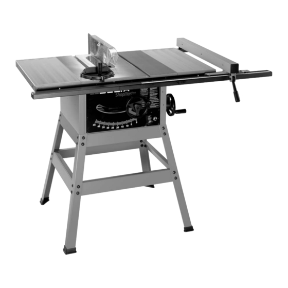
FOREWORD Delta ShopMaster Model TS300 is a 10" Table Saw designed to give high quality performance with depth of cut capacity up to 3-1/8" (79mm) at 90° and 2-1/8" (54mm) at 45° for clean cutting of standard stock sizes. Delta ShopMaster Model TS300 includes the basic machine, a sturdy steel stand, a T-Square fence system, a T-Slot miter gauge, a 15 amp. - Page 8 1. Table Saw 2. Extension Wing (2) 3. Rip Fence 4. Miter Gage 5. Rip Fence Handle 6. Handwheel (2) 7. M10 Flat Washer (2), Used to mount handwheel lock knob 8. Handwheel Lock Knob (2) 9. Right Front Rail 10.
-
Page 9: Assembly
For Saw Stand Top Front and Rear Braces - 19" in length Bottom Front and Rear Braces - 22-1/2" in length (2) Stand Legs (4) Feet (4) 3/8" Flat Washer (32) M8x1.25x16mm Carriage Head Screw (32) M8x1.25 Hex Nut (32) Bottom Side Braces - 20"... -
Page 10: M8.1
ATTACHING THE SAW TO THE STAND Invert the saw table face down on a piece of cardboard to protect the table surface. Align the four holes in the saw cabinet with the four holes in the stand. Place a 3/8" flat washer on an M8 x 1.25 x 16mm hex head screw. -
Page 11: Flat
CHANGING THE BLADE DISCONNECT THE MACHINE FROM THE POWER SOURCE. Use only 10" diameter saw blades, rated for 6000 rpm or higher with 5/8" arbor holes. NOTE: Two 7/8" wrenches are supplied with the saw for changing the saw blade - a box-end wrench and an open- end wrench. -
Page 12: M6X1 Hex
GUIDE RAILS Align the three slotted holes in the front right guide rail (A) Fig. 14 with the two holes (B) in the saw table and the slotted hole (C) in the extension wing. Insert an M6 x 1 x 20mm carriage head screw (D) Fig. 14 through the three holes in the front right guide rail and the saw table. -
Page 13: Rip Fence Handle 6
RIP FENCE 1. Insert the handle (A) Fig. 19 into the threaded hole (B) in the rip fence (C). 2. Insert a flat-head screwdriver into the rip fence handle (A) Fig. 20 and tighten the screw. 3. Tighten the hex nut (D) Fig. 20 against the fence body. Fig. - Page 14 BLADE GUARD AND SPLITTER ASSEMBLY DISCONNECT THE MACHINE FROM THE POWER SOURCE. Thread an M12 x 1.75 hex nut (A) Fig. 26 on the splitter support rod (R), as far as it will go. Place a 5/8" flat washer (B) Fig. 26 on the splitter support rod (R).
-
Page 15: Operation
OPERATION OPERATIONAL CONTROLS AND ADJUSTMENTS STARTING AND STOPPING THE SAW 1. The on/off switch (A) Fig. 30 is located on the front of panel of the saw. To turn the machine “ON”, move the switch up to the “ON” position. 2. - Page 16 ADJUSTING 90° AND 45° POSITIVE STOPS Fig. 34 Fig. 33 Your saw is equipped with positive stops that will position the saw blade at 90° and 45° to the table. To check and adjust the positive stops: DISCONNECT THE MACHINE FROM THE POWER SOURCE. Turn the blade-tilting handwheel clockwise as far as it will go.
- Page 17 RIP FENCE OPERATION AND ADJUSTMENTS Properly align the rip fence to the miter gauge slot and the saw blade to prevent kickback. To move the fence (A) Fig. 38 along the guide rails, lift up on the fence locking lever (B), slide the fence to the desired location, and push down on the locking lever (B).
-
Page 18: Adjusting The Table Insert
However, if you overlook or ignore normal safety precautions, personal injury can result. The following information describes the safe and proper method of performing the most common sawing operations. The use of attachments and accessories not recommended by Delta may result in the risk of injury. CROSS-CUTTING Cross-cutting requires the use of the miter gauge to position and guide the work. - Page 19 RIPPING Ripping is the operation of making a lengthwise cut through a board (Fig. 46), and the rip fence (A) is used to position Fig. 46 and guide the work. One edge of the work rides against the rip fence while the flat side of the board rests on the table. Since the work is pushed along the fence, it must have a straight edge and make solid contact with the table.
- Page 20 For certain cutting operations such as dadoing and moulding where you are not cutting completely through the workpiece, DO NOT USE the blade guard and splitter assembly. Always return and fasten the blade guard and splitter assembly to its proper operating position for normal through-sawing operations.
- Page 21 Dadoing is cutting a rabbet or wide groove into a workpiece. Most dado head sets are made up of two outside saws and four or five inside cutters (Fig. 52). Various combinations of saws and cutters are used to cut grooves from 1/8" to 13/16"...
-
Page 22: Constructing A Featherboard
USING AUXILIARY WOOD FACING ON RIP FENCE When performing a moulding operation, add a wood facing (A) Fig. 57 to one or both sides of the rip fence. Attach the wood facing to the fence with wood screws. Install and countersink these screws through the holes provided in the fence. -
Page 23: Constructing A Push Stick
CONSTRUCTING A PUSH STICK When ripping work less than 4" wide, use a push stick to complete the feed You can make one from scrap material by using the pattern shown here. -
Page 24: Troubleshooting
TROUBLESHOOTING For assistance with your tool, visit our website at www.deltamachinery.com for a list of service centers or call the DELTA Machinery help line at 1-800-223-7278 (In Canada call 1-800-463-3582). MAINTENANCE KEEP MACHINE CLEAN LUBRICATION Apply household floor paste wax to the machine table and Periodically blow out all air passages with dry compressed air. -
Page 25: Service
SERVICE PARTS, SERVICE OR WARRANTY ASSISTANCE All Delta Machines and accessories are manufactured to high quality standards and are serviced by a network • of Porter-Cable Delta Factory Service Centers and Delta Authorized Service Stations. To obtain additional information regarding your Delta quality product or to obtain parts, service, warranty assistance, or the location of the nearest service outlet, please call 1-800-223-7278 (In Canada call 1-800-463-3582). -
Page 26: Warranty
Two Year Limited New Product Warranty Delta will repair or replace, at its expense and at its option, any new Delta machine, machine part, or machine accessory which in normal use has proven to be defective in workmanship or material, provided that the customer returns the product prepaid to a Delta factory service center or authorized service station with proof of purchase of the product within two years and provides Delta with reasonable opportunity to verify the alleged defect by inspection. -
Page 27: Español
Fax: (519) 767-4131 Fax: (604) 420-3522 Fax: (514) 336-3505 The following are trademarks of PORTER-CABLE • DELTA (Las siguientes son marcas registradas de PORTER-CABLE • DELTA S.A.) (Les marques suivantes sont des marques de fabriquant de la PORTER-CABLE • DELTA): Auto-Set ®...
Need help?
Do you have a question about the ShopMaster TS300 and is the answer not in the manual?
Questions and answers