
Related Manuals for FASTRON. FTM1 Series


Summary of Contents for FASTRON. FTM1 Series
- Page 1 FTM1 TYPE SCR power controller FTM1 Type series (Single Phase) User manual of full digital single phase SCR power controller - 1 -...
-
Page 2: Preface
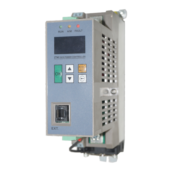
FTM1 TYPE SCR power controller Preface Product appearance drawing First use Users who use this product for the first time should read this manual carefully. If you have doubts about some functions and performance, please consult our technical support personnel for help, which is beneficial to the correct use of this product. -
Page 3: Table Of Contents
FTM1 TYPE SCR power controller Contents Preface ................................- 2 - Safety precautions ............................- 5 - Product information ............................- 12 - Data plate and type definition ......................- 12 - Technical specification ........................- 13 - Product specification and installation..................... - 14 - 2 System connection ............................ - Page 4 FTM1 TYPE SCR power controller Appendix A: Function parameter table ......................- 29 - Appendix B: Control Logic ........................- 36 - Appendix C: General parameter table ......................- 37 - - 4 -...
-
Page 5: Safety Precautions
FTM1 TYPE SCR power controller Safety precautions Safety note ⚫ Please read and observe this safety note before installing, operating and maintaining the product. ⚫ In order to ensure personal and equipment safety, please follow the product identification and all safety precautions in the manual when installing, operating and maintaining the product. - Page 6 FTM1 TYPE SCR power controller Safety precautions Open package acceptance Caution ⚫ Before unpacking, please check whether the outer package of the product is in good condition, whether it is damaged, soaked, damped, deformed, etc. ⚫ Please open the package according to the order of layers. Do not knock it violently! ⚫...
- Page 7 FTM1 TYPE SCR power controller ⚫ Please pack the products strictly and transport them by vehicle. More closed boxes must be used for long-distance transportation. ⚫ It is strictly forbidden to transport the product together with equipment or goods that may affect or damage the product.
- Page 8 FTM1 TYPE SCR power controller ⚫ It is strictly forbidden to install, connect, protect, maintain, inspect or replace parts by non professionals! ⚫ The installation, wiring, maintenance, inspection or component replacement of this product can only be carried out by professionals who have received relevant training of electrical equipment and have sufficient electrical knowledge.
- Page 9 FTM1 TYPE SCR power controller Danger ⚫ Before power on, please make sure that the equipment and products are installed in good condition and the wiring is firm. ⚫ Before power on, please make sure that the power supply meets the requirements of the equipment to avoid equipment damage or fire! ⚫...
- Page 10 FTM1 TYPE SCR power controller otherwise the equipment will be damaged! Maintenance Danger ⚫ It is strictly forbidden for non professional personnel to carry out equipment installation, wiring, maintenance, inspection or component replacement! ⚫ It is strictly forbidden to maintain the equipment under the power on state, otherwise there is a risk of electric shock! Warning lease carry out daily and regular inspection and maintenance of the equipment and products...
- Page 11 FTM1 TYPE SCR power controller again. Scrap Warning ⚫ Please scrap the equipment and products according to the relevant national regulations and standards, so as to avoid property loss or casualties! ⚫ Scrap equipment and products should be treated and recycled according to the industrial waste treatment standards to avoid environmental pollution.
-
Page 12: Product Information
FTM1 TYPE SCR power controller Product information 1.1 Data plate and type definition Data plate FTM1 FTM1-AO75-V2-WO 230VAC Fig.1-1 Data plate Type definition FTM1 - A080 V4 2 W0 Mark Product name Mark External control panel options FTM1 None Power controller series External control panel + 1 meters display line Mark... -
Page 13: Technical Specification
FTM1 TYPE SCR power controller 1.2 Technical specification Item Specification Main circuit voltage AC 230、AC400、AC500、AC690 (frequency: 30-65HZ) Control power supply 100~240VAC ɑ、U、I、P、U 、I Control mode Operation mode Phase mode, cycle mode Output voltage 0-98% of the main circuit power supply Output current ee specification Communication bus... -
Page 14: Product Specification And Installation
FTM1 TYPE SCR power controller ~ Storage temperature -20℃ +60℃ Installation Vertical position, screw installation 1.3 Product specification and installation Model Rated current Cooling mode FTM1-A020 □□ □□ □□ Natural cooling FTM1-A040 □□ □□ □□ Air cooling FTM1-A060 □□ □□ □□ Air cooling FTM1-A080 □□... - Page 15 FTM 1 TYPE SCR power controller Fig. 1-4 outline dimension and installation dimension of FTM1 series (With optional Heat/Dust Cover) - 15 -...
-
Page 16: System Connection
2 System connection FTM1 series system connection diagram When using FTM1 series power controller to constitute the system, it is necessary to install all kinds of electrical components at the controller input side to ensure the safety and stability of the system. The system structure of FTM1 series power controller is shown in the figure below: AC30~690V... -
Page 17: Description Of Zty1 Series System Composition
Peripheral options include external lead operation and functional expansion controller, as shown in the table below. For detailed usage, please refer to the instructions of the accessory. If you need the following options, please specify when ordering. Table 2-2 list of FTM1 series power controller options Name Model... -
Page 18: Installation And Wiring
FTM 1 TYPE SCR power controller 3 Installation and wiring 3.1 Installation 3.1.1 Installation environment Ambient temperature: The ambient temperature has a great influence on the life of the power controller. The ambient temperature of the power controller is not allowed to exceed the allowable temperature range (- 10 ℃ ~ 50 ℃). Install the power controller on the surface of the flame retardant object, and there should be enough space around it to dissipate heat. -
Page 19: Wiring
FTM 1 TYPE SCR power controller 3.2 Wiring 3.2.1 Reference wiring diagram AC30~690V Load External display interface 4~20mA 0~5V/0~10V CAN+ communication CAN- interconnection Start Alarm relay output Manual / auto Reset AC110/AC220V Fan control RS485 MODBUS Fig. 3-1 reference wiring diagram - 19 -... -
Page 20: Description Of Main Circuit Terminal
FTM 1 TYPE SCR power controller 3.2.2 Description of main circuit terminal Terminal marking Terminal name Function description Main circuit Main power supply, AC30 ~ input 690V Main circuit Connect to load output 3.2.3 Description of control circuit terminal Terminal Terminal name Function description symbol... - Page 21 FTM 1 TYPE SCR power controller common terminal A+, B- RS485 MODBUS communication port communication port FP1, FP2 AC110V/AC220V, same level as control Fan power supply power supply Y1, YM Alarm relay output Passive relay, 220VAC/30VDC 5A - 21 -...
-
Page 22: Pannel Operation
FTM 1 TYPE SCR power controller 4 Pannel operation 4.1 Pannel introduction Through the operation pannel, you can set / modify the function code, monitor the working state, and control the operation (start and stop) of the power controller. FAULT 220.0 50.0 11.0... -
Page 23: Function Indicator
FTM 1 TYPE SCR power controller 4.3 Function indicator : The operation indicator light is not on when the controller is shut down, but is always on when the controller is in normal operation. : Auto / manual indicator light. It is off when terminal A / M is disconnected from M, and it is always on when terminal A / M and M are short circuited. -
Page 24: Fault Handling
FTM 1 TYPE SCR power controller 5 Fault handling 5.1 Fault alarm and solutions The power controller may encounter the following faults in the use process. Please refer to the following methods for simple fault analysis: Fault Fault cause Solutions description The ambient Reduce ambient temperature... -
Page 25: Daily Maintenance
FTM 1 TYPE SCR power controller 6 Daily maintenance 6.1 Daily maintenance Please make sure to check the function of the controller every time after confirming that it is not damaged. Please make a copy of the inspection confirmation form for use, and stamp the "confirmation"... -
Page 26: Regular Inspection
FTM 1 TYPE SCR power controller the main circuit load starting around and the control circuit is abnormal 6.2 Regular inspection Item Contents Solutions Inspection ⚫ Confirm whether the power controller is powered off; ⚫ Whether any Use vacuum cleaner to remove accumulation of garbage or dust to avoid contacting Complete... -
Page 27: Replacement Of Wearing Parts Of Power Controller
FTM 1 TYPE SCR power controller Whether the control components are in ⚫ Clean the foreign matters on the poor contact; surface of control circuit and Control whether the connecting terminal; loop terminal screw is ⚫ Replace the damaged and corroded loose;... - Page 28 FTM 1 TYPE SCR power controller abnormally. Fan replacement method: 6.4 Power controller storage After purchasing the power controller, the following points must be paid attention to for temporary storage and long-term storage: When storing, try to pack them into the packing box of our company according to the original packing.
- Page 29 FTM1 TYPE SCR power controller Appendix A: Function parameter table “R” : Indicates that the parameter displays the actual test record value and cannot be changed; “W” : Indicates that the setting value of the parameter can be changed when the power controller is in shutdown and running state;...
- Page 30 FTM1 TYPE SCR power controller 0.12 Communication 0.00~100.00% input (%) 0.00~100.00% 0.13 Input total (%) 0.14 U feedback (%) 0.00~120.00% Voltage feedback (%) 0.00~120.00% 0.15 I feedback (%) Current feedback (%) P feedback Power feedback 0.16 0.00~120.00% Total feedback 0.00~120.00% Total feedback 0.17 Grid...
- Page 31 FTM1 TYPE SCR power controller setting is valid. 0: Stop 1: Run Set start signal source 0~5 1.02 Start & stop source 0: Terminal RUN control 1: Communication control 2: Expansion pannel control start & stop 3:The terminal and communication are effective at the same time 4: Expansion pannel and communication are...
- Page 32 FTM1 TYPE SCR power controller 1:Phase shifting constant voltage 2:Phase shifting constant current 3:Phase shifting constant power 4:Zero crossing open loop 5:Zero crossing constant voltage 6:Zero crossing constant current 7:Zero crossing constant power 8:Variable period open loop 9:Variable period constant voltage 10:Variable period constant current...
- Page 33 FTM1 TYPE SCR power controller signal source Refer logic diagram in Appendix 0~32767 Use with 1.13 1.12 Communication set 1.12 ÷ 1.13 1.13 Communication set 0~32767 communication set % rating 0: AI2 input 0 ~ 5V 0、1 1.14 AI2 range signal 1:AI2 input 0 ~...
- Page 34 FTM1 TYPE SCR power controller 0.500 Voltage PID setting 1.22 Voltage loop P 0.000~32.767 0.000~32.767 0.300 1.23 Voltage loop I 0.000~32.767 0.000 1.24 Voltage loop D 0.000~32.767 0.300 Current PID setting 1.25 Current loop P 0.000~32.767 0.200 1.26 Current loop I 0.000~32.767 0.000 1.27...
- Page 35 FTM1 TYPE SCR power controller 0: No fault 2.13 Main loop fault 0、1 1: Fault Lower limit of 10.0~1000.0 30.0 Alarm when the power 2.14 grid voltage (V) grid is lower than this value 3 .System information 3.01 Software version 3.02 Rated voltage (V) 3.03...
- Page 36 FTM1 TYPE SCR power controller Appendix B: Control Logic - 36 -...
- Page 37 FTM1 TYPE SCR power controller Appendix C: General parameter table - 37 -...